2. My Final Virtual Mould
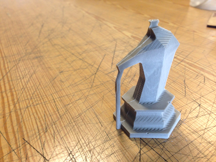
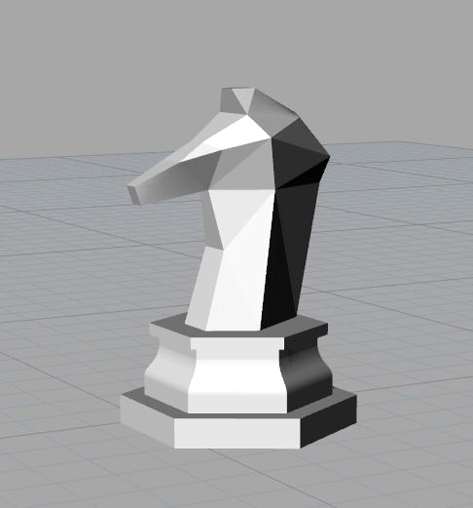
After experimenting with different moulds, I decided to create my personal chess. Starting with the knight, I am looking for a clean design made out of triangles, except for the base, that has an hexagonal shape with a curved surface.
AS I do not have that much time, I am going to concentrate in this piece, moulding it and casting it to learn the whole process first before designing the other chess parts.
DESIGNING THE MOULD
Starting with a quick plan of my wax piece, first I divided the piece in two parts + creating a 1'20 cm wall for silicone to stay strong while curing itself and casting the plaster.
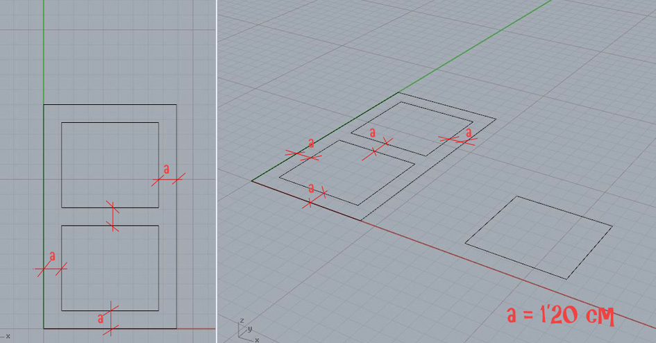
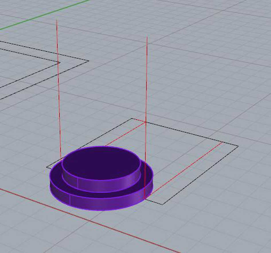
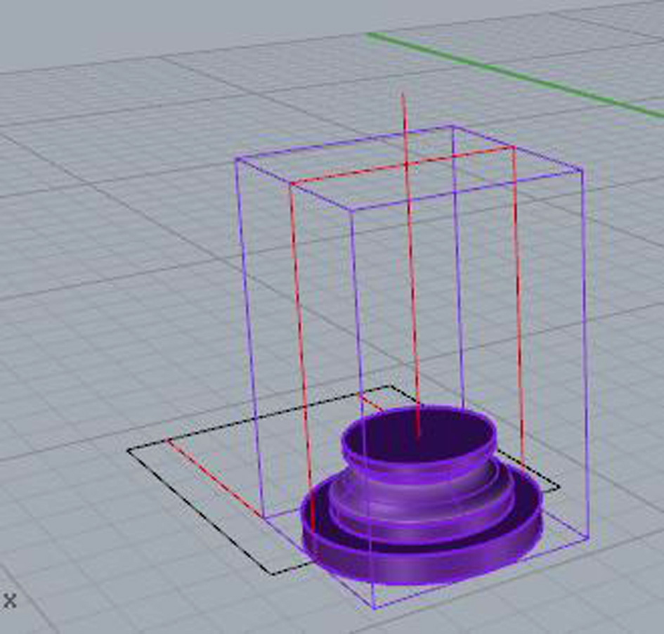
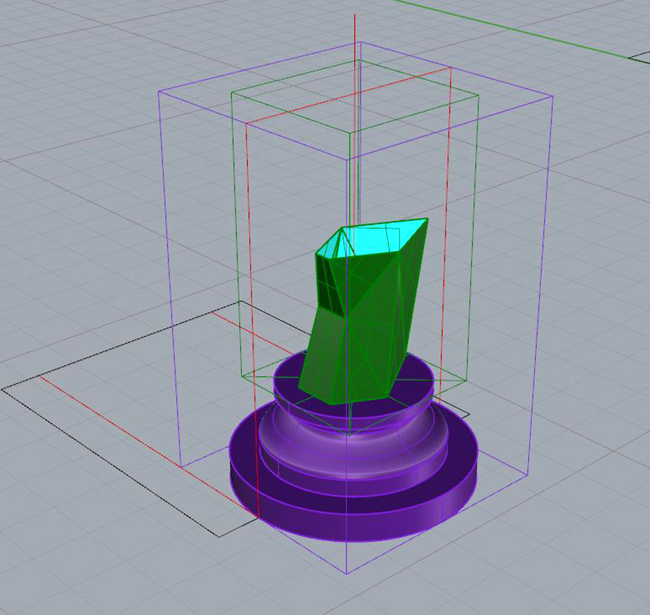
After realising the material limitation that I had, I started designing my piece from the base upwards. Very important to know the maximum height of my possible piece. Auxiliary lines (purple and red) drawn to make sure I did not have trouble later on.
First I thought about a cylindrical shape and experiment with the revolving tools that Rhino has.
Then, while building up the figure, I decided to turn into a triangle-shaped piece:
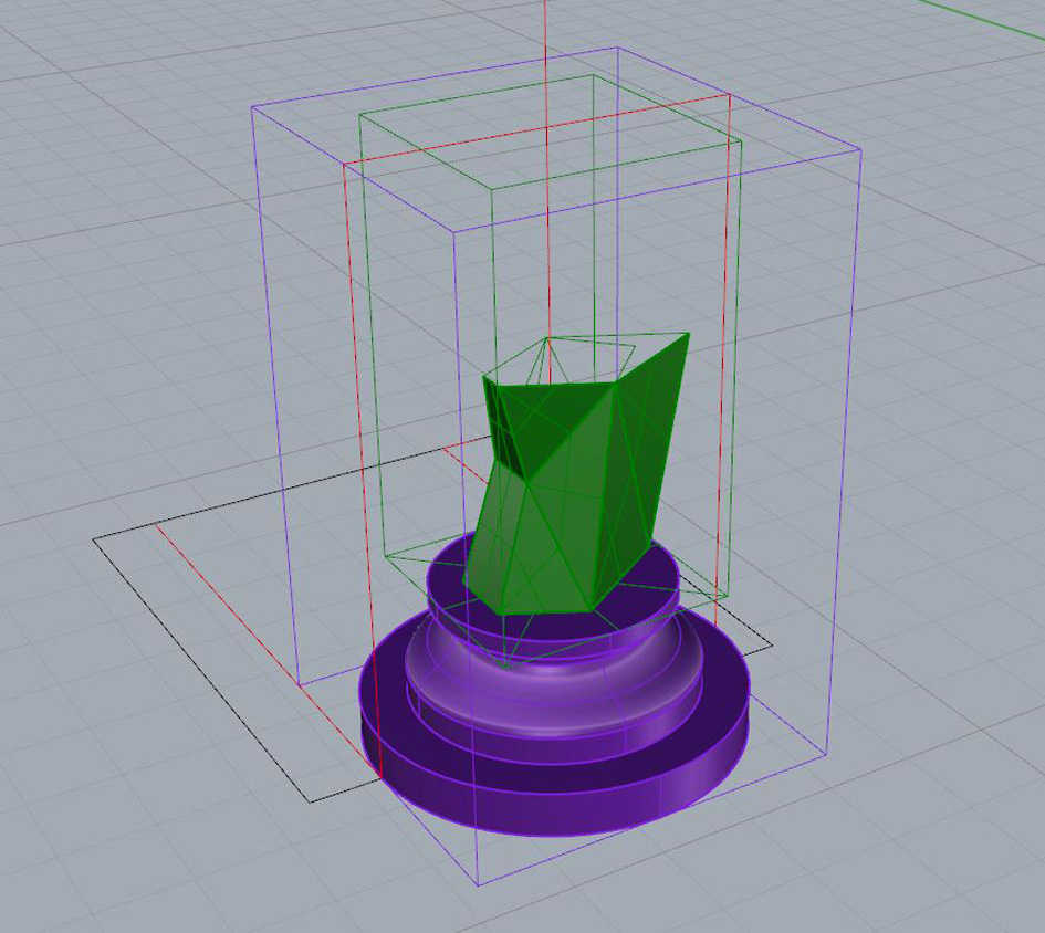
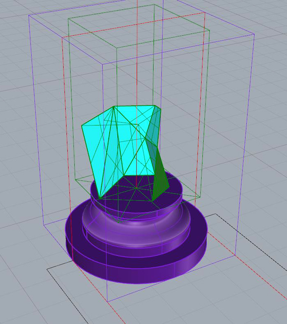
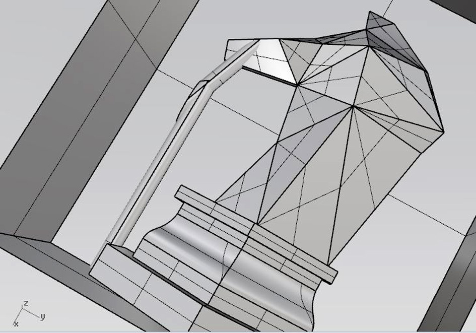
The I built the shape was really simple: starting with multiple auxiliary lines joined together creating the figure. Just below you can see how I built the head:
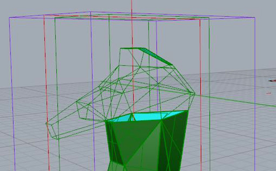
I had to change several times the shape, as first I had a dog shape rather than a horse.
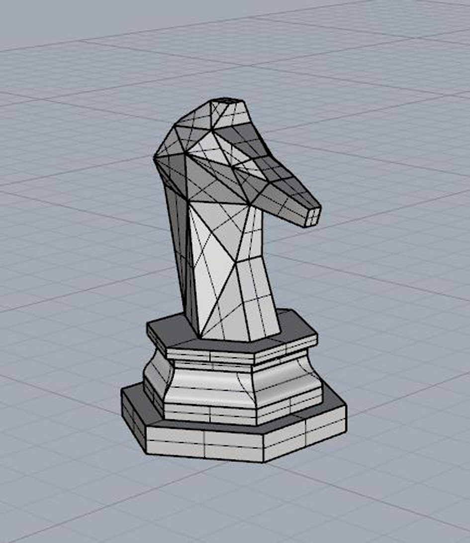
Finally, happy with the design, I decided to change the base as the cylindered shape was not what I was looking for. The final base has a hexagonal shape based on the initial cylindrical base.
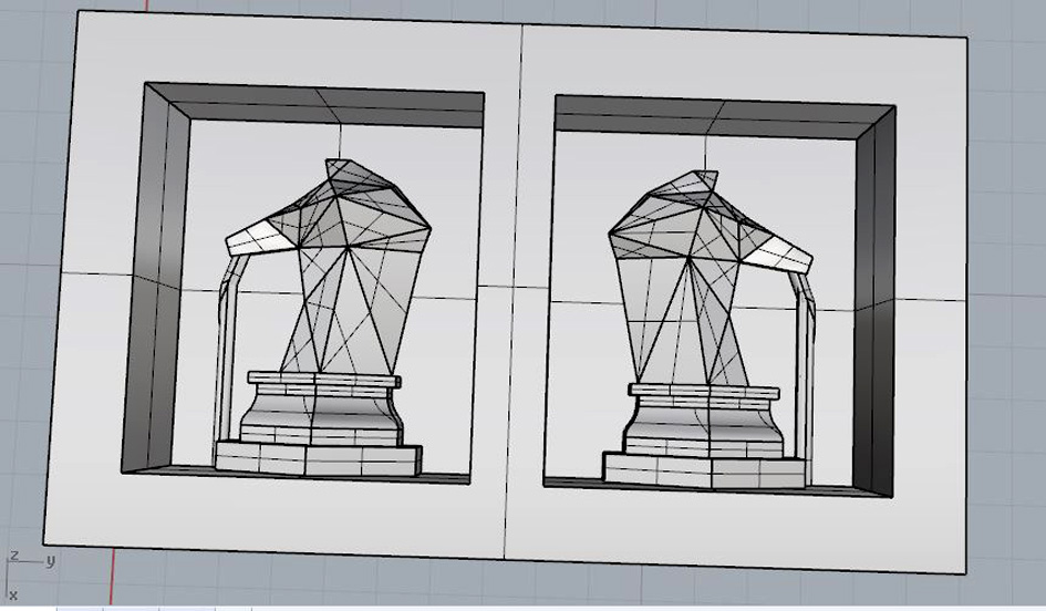
Final virtual piece:
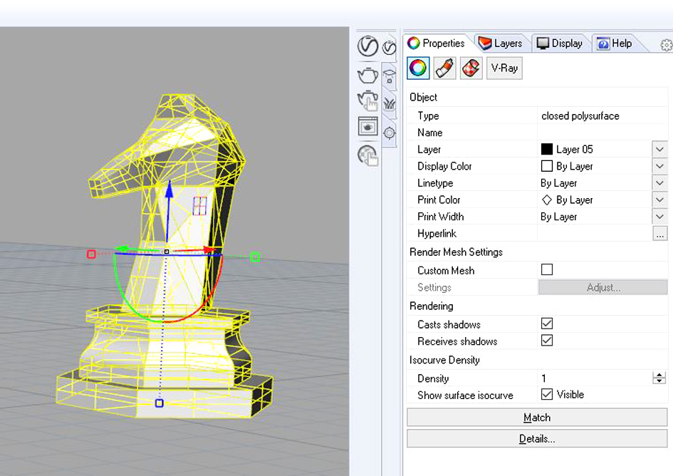
Joining all parts together, I had no problems having a closed polysurface:
CREATING THE VIRTUAL MOLD
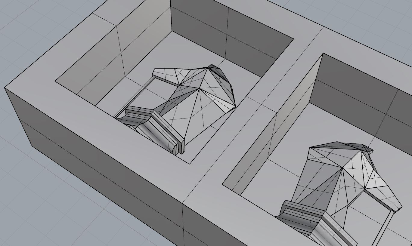
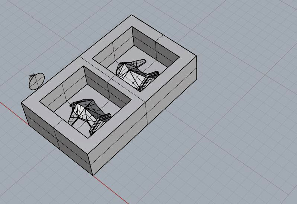
Starting drawing the wax mould ( 150x89x37mm) + cutting the knight in half, corresponding one half to each side.
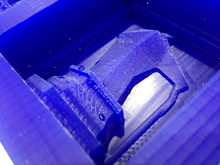
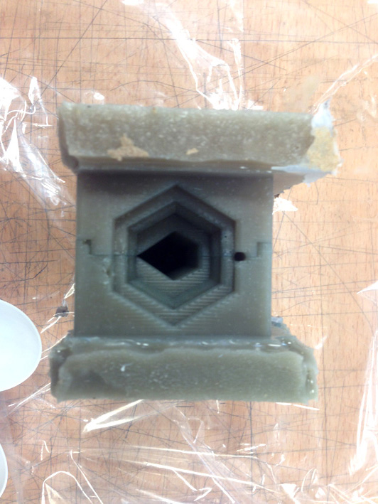
Very important to mention: I needed a good ventilation so air does not get trapped inside the mould while casting the plaster. On the horse's nose, I have designed a cylindrical shape to let the air come out while pouring and filling up the silicone mould. At first, I had a minimal ventilation pipe, but after discussing with my instructor, I made it bigger one to assure the air does not get trapped.
(small ventilation cylinder)
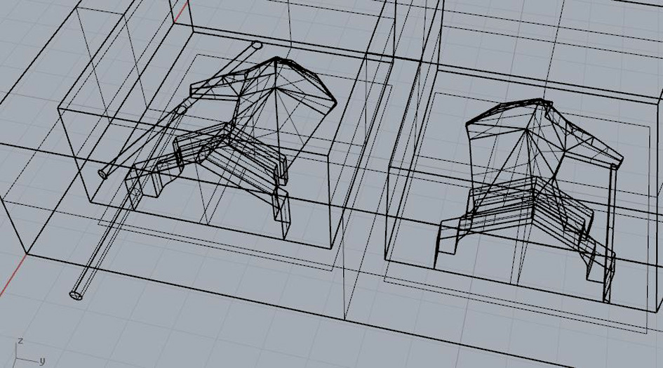
Bigger Ventilation
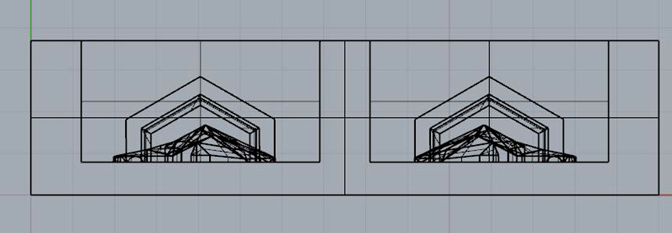
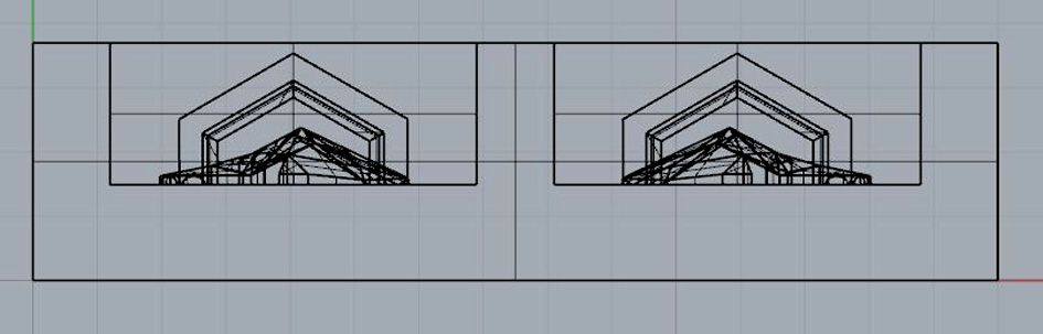
Here is a top view so far...
and a side view
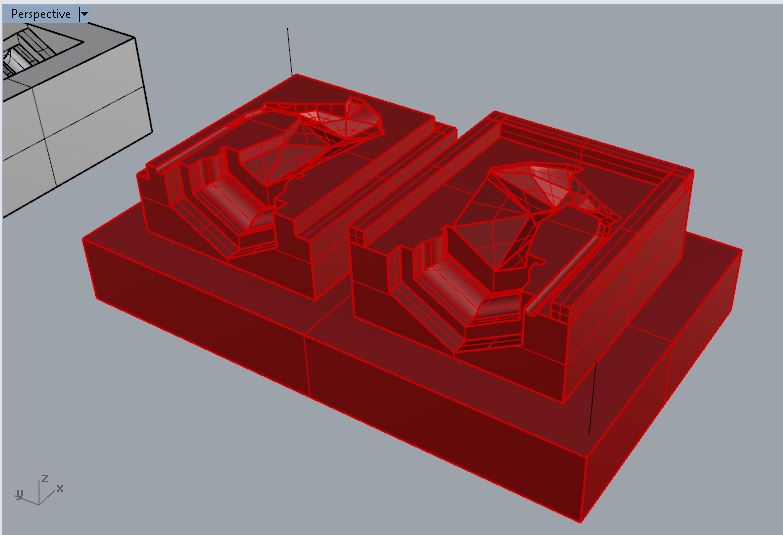
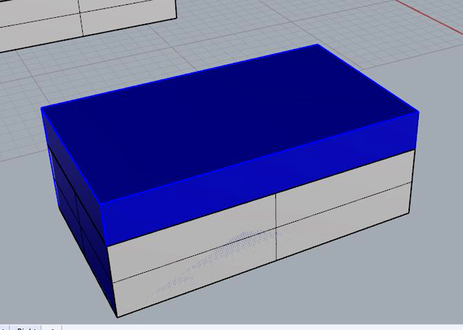
Considering the amount of material the milling machine has to take from the mould, my instructor suggested me to elevate both figures to the maximum possible height to save more time. As I will need to use DM wood to stop the silicone from spilling over the mould, I can reduce the amount of material being milled from the machine by rising the DM's height when curing the silicone.
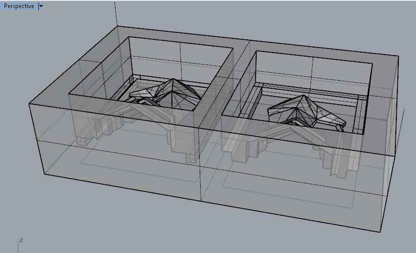
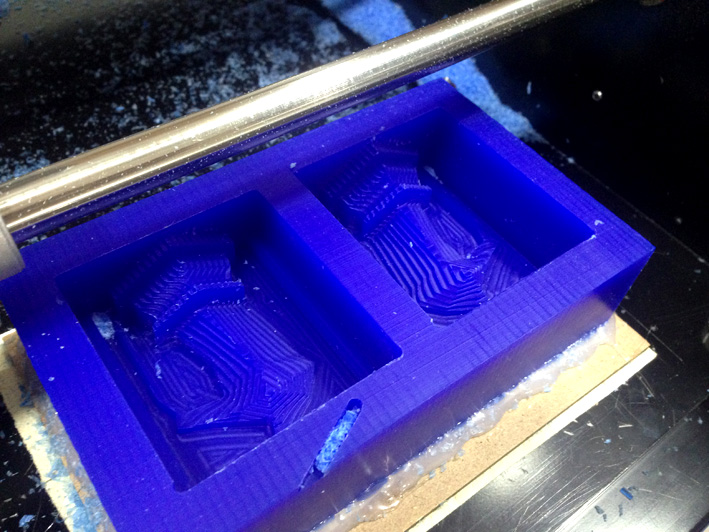
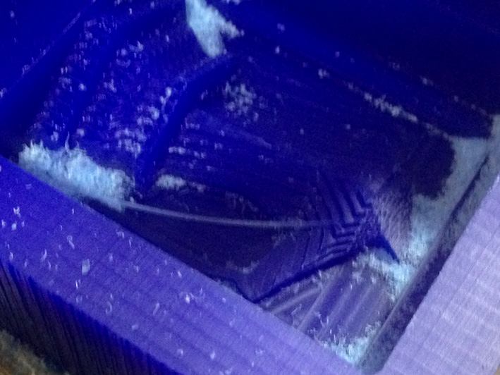
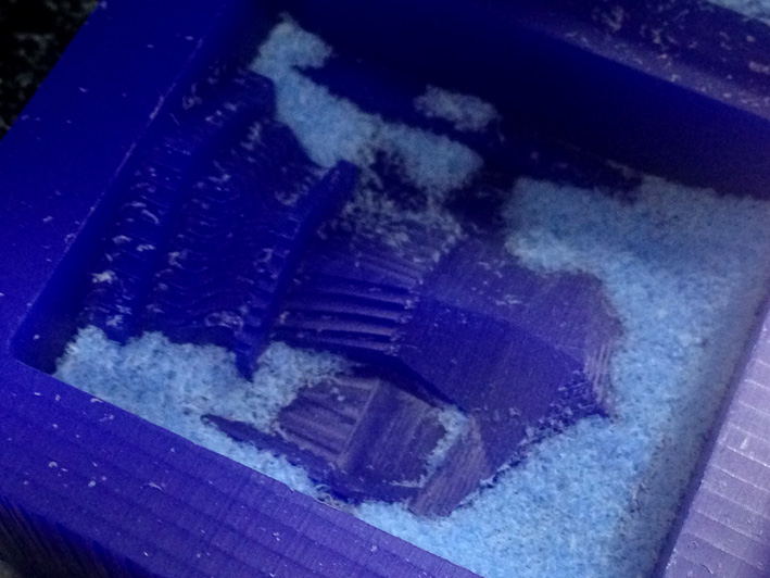
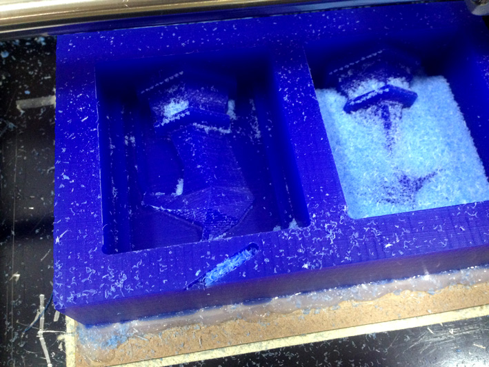
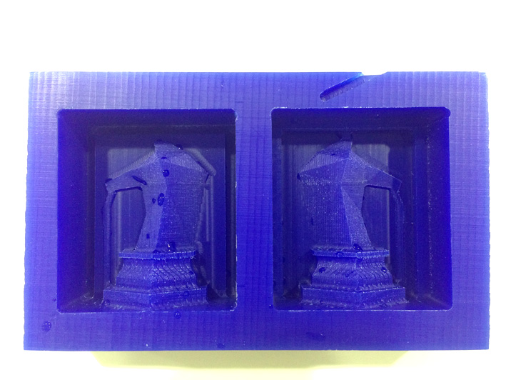
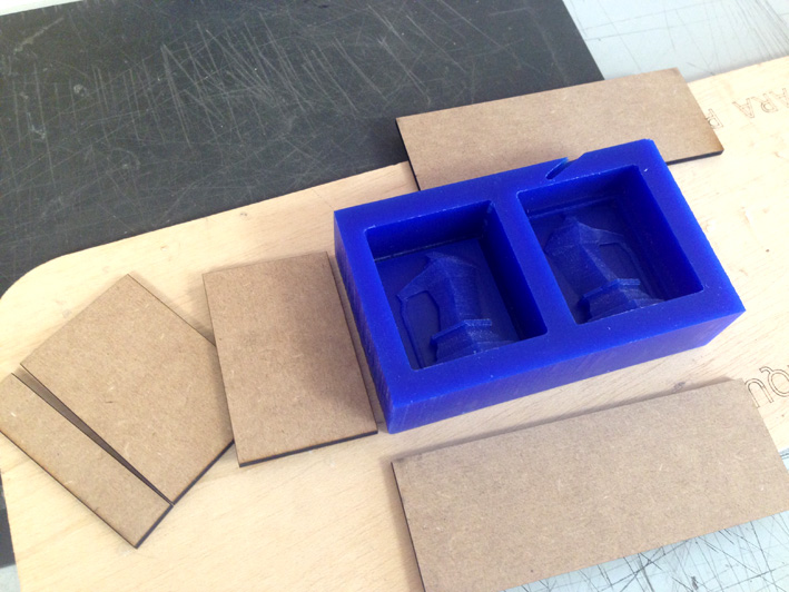
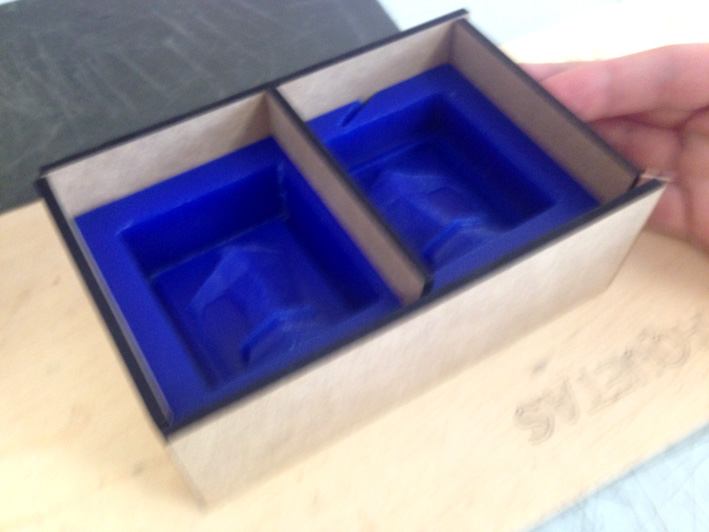
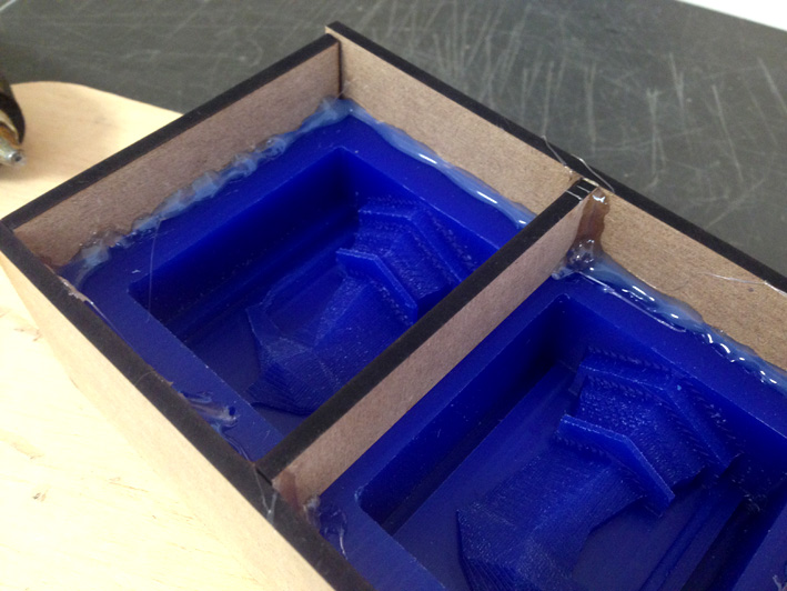
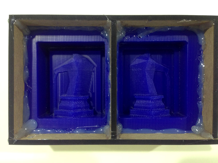
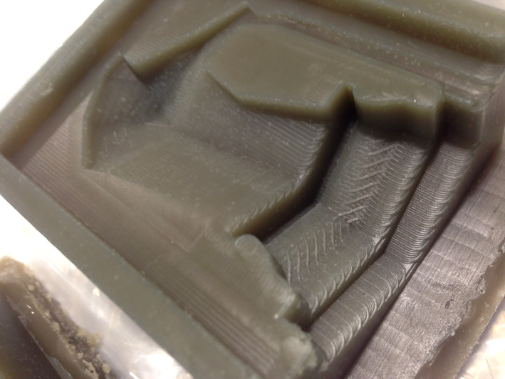
THE 1ST COMPLETE MOULD
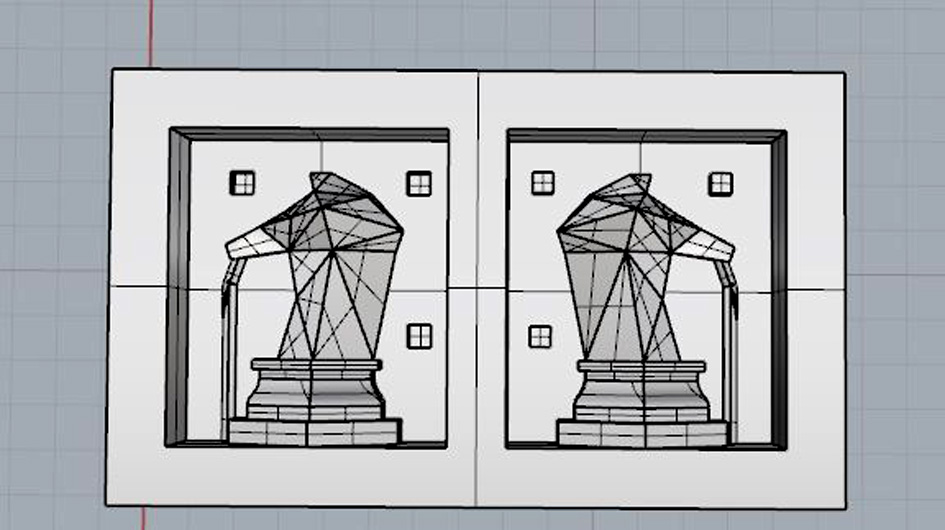
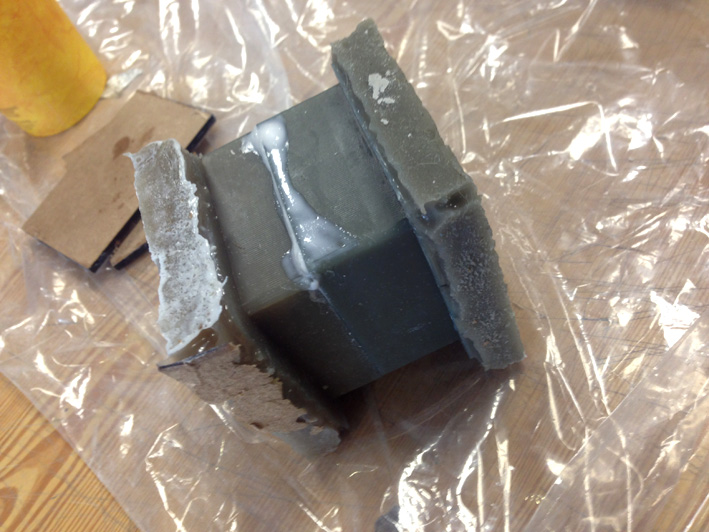
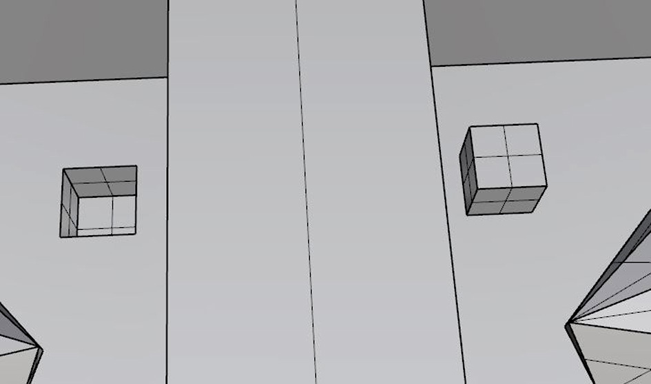
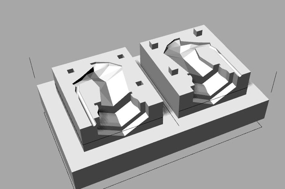
As I am the last one of my lab to mill the mould for this week's assignment, some of my colleagues have had problems with the spherical joints. Therefore, I considered to instead of being spherical, to be cubed so the mould comes together without moving one piece from the other.
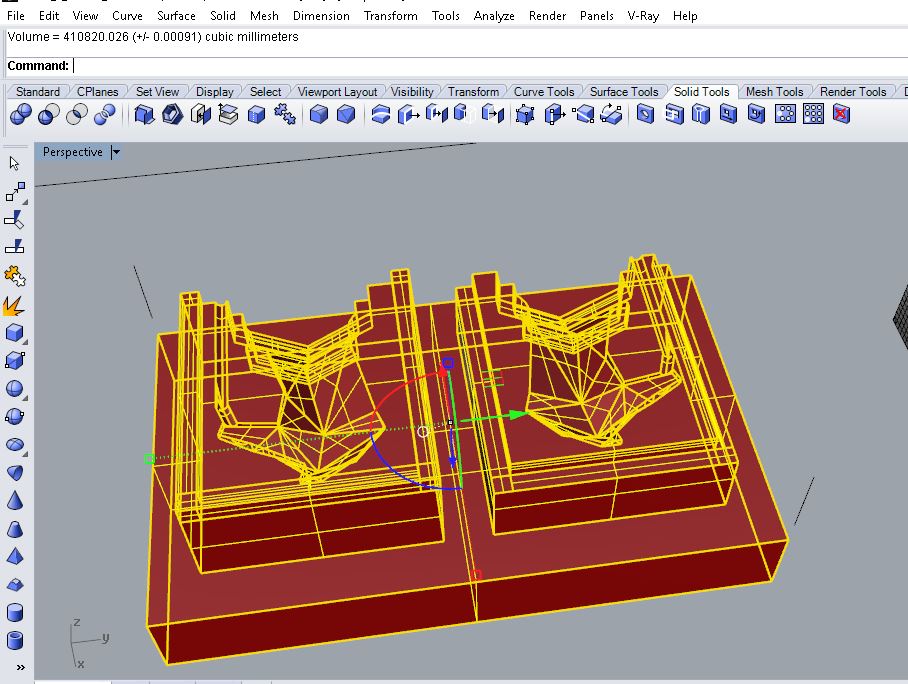
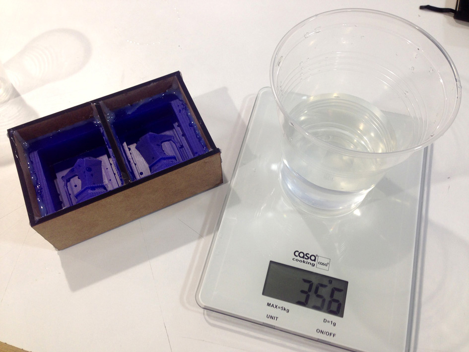
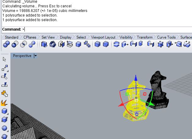
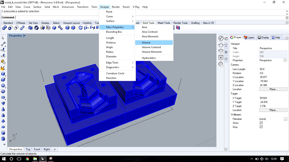
CALCULATING THE VOLUME NEEDED
To calculate mould's volume, Rhino's is very quick. We have a negative copy of our mould and calculate its volume with 'Analyse-->Mass Properties-->Volume'.
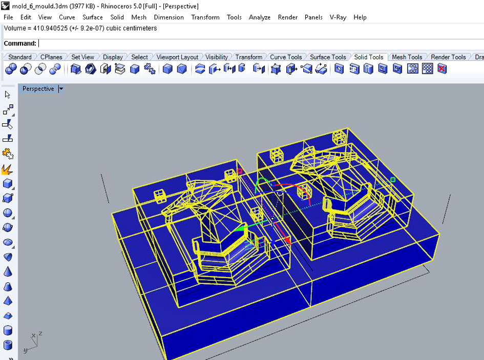
In total: 410 cm3 of material will be used.
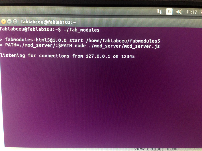
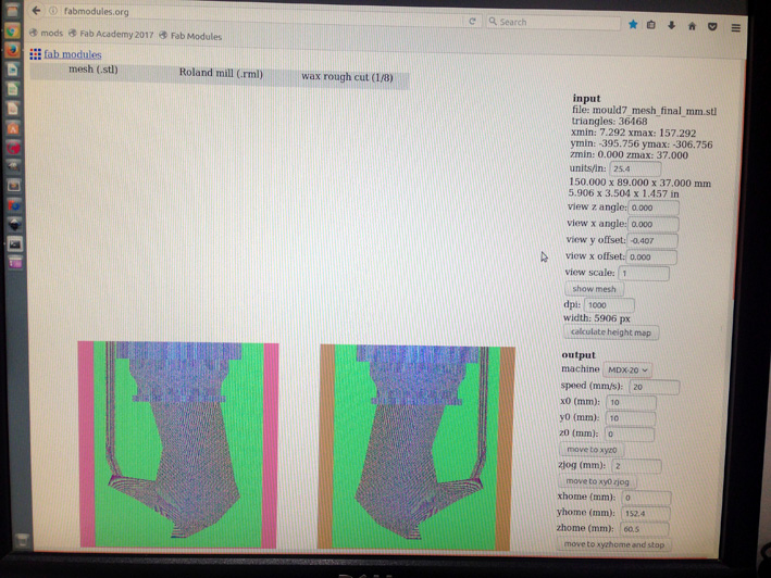
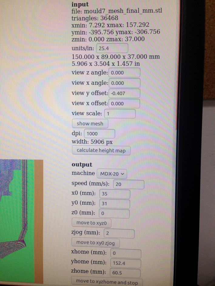
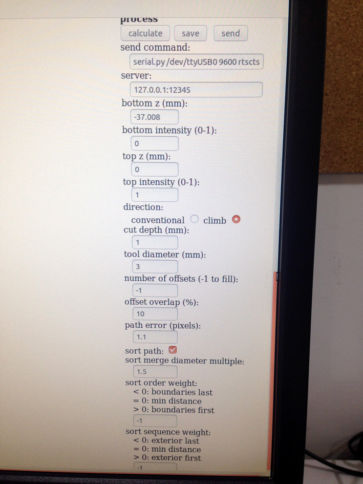
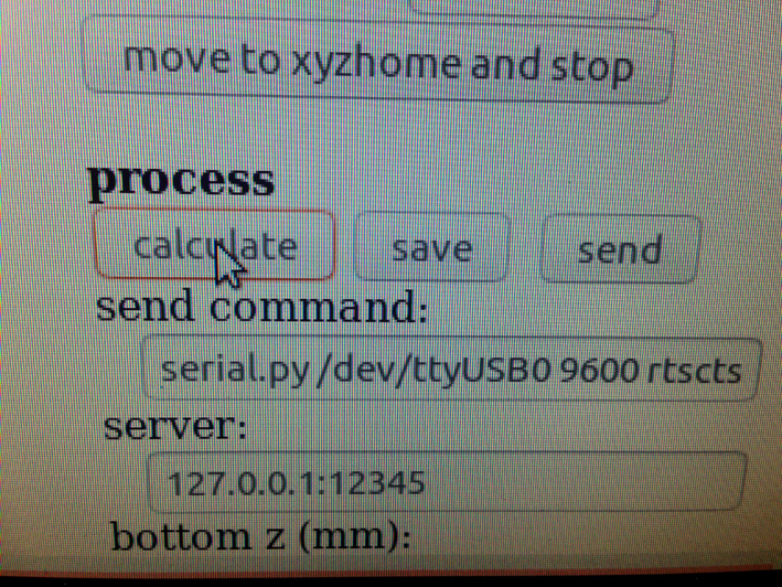
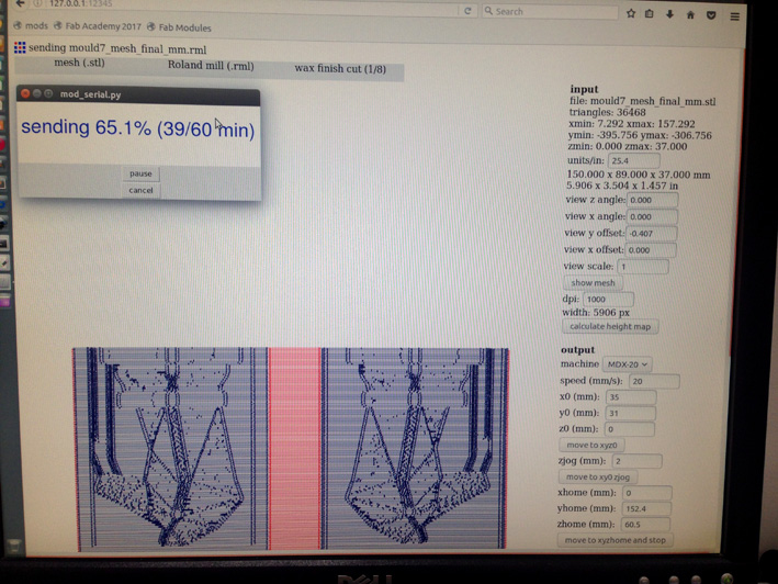
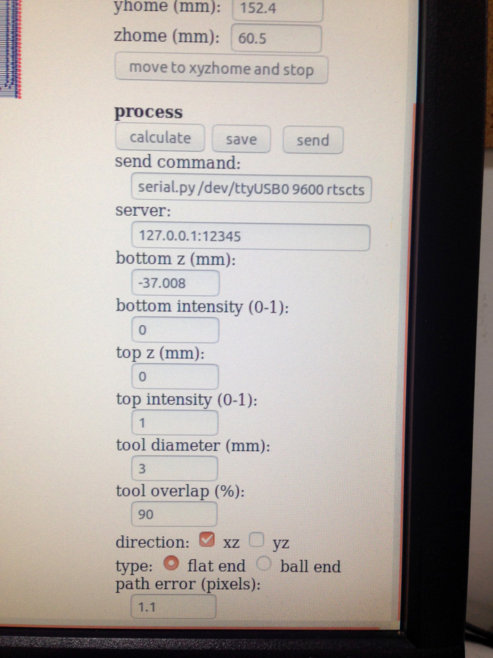
CHECKING ON FAB MODULES
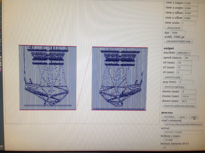
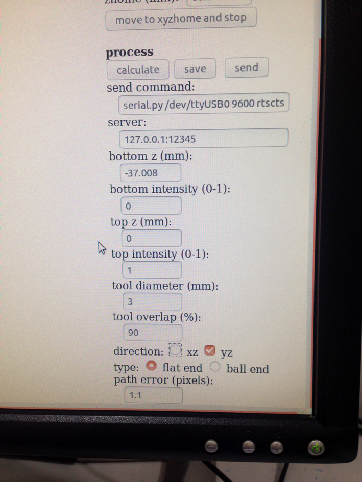
To make sure everything is going the right way, I entered Fab Modules and loaded my .STL file onto it.
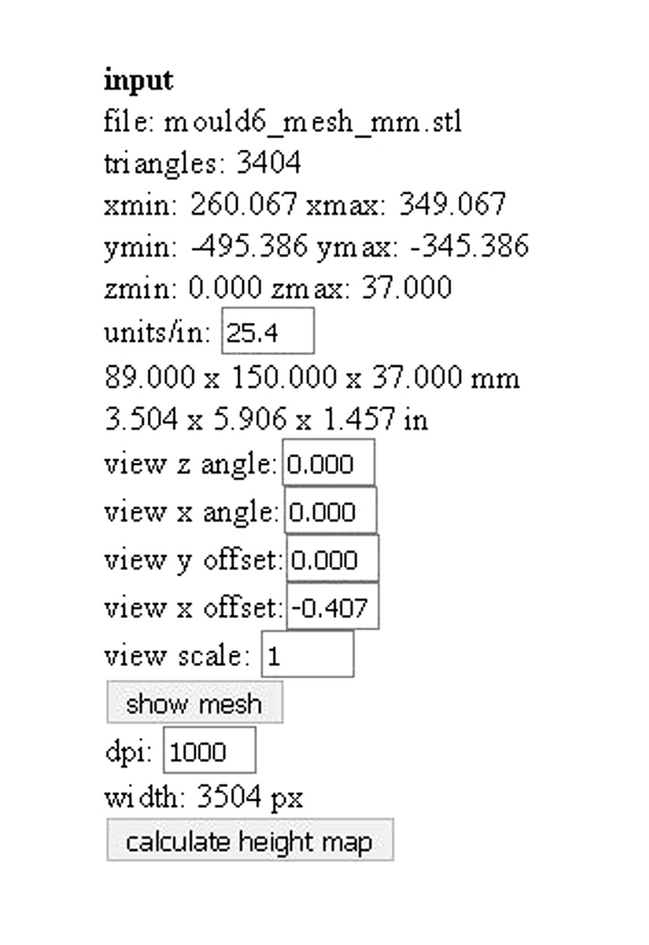
After converting the inches to mm, everything seems to be OK.
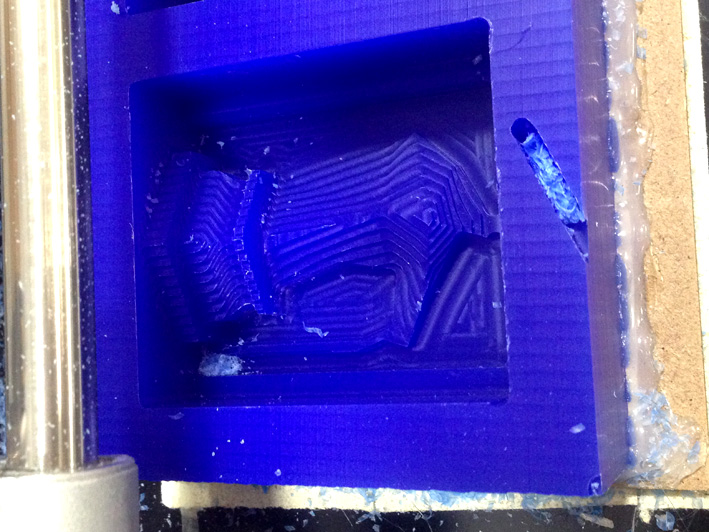
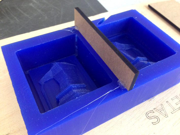
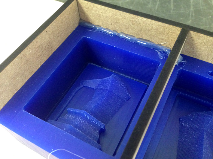
CHANGES
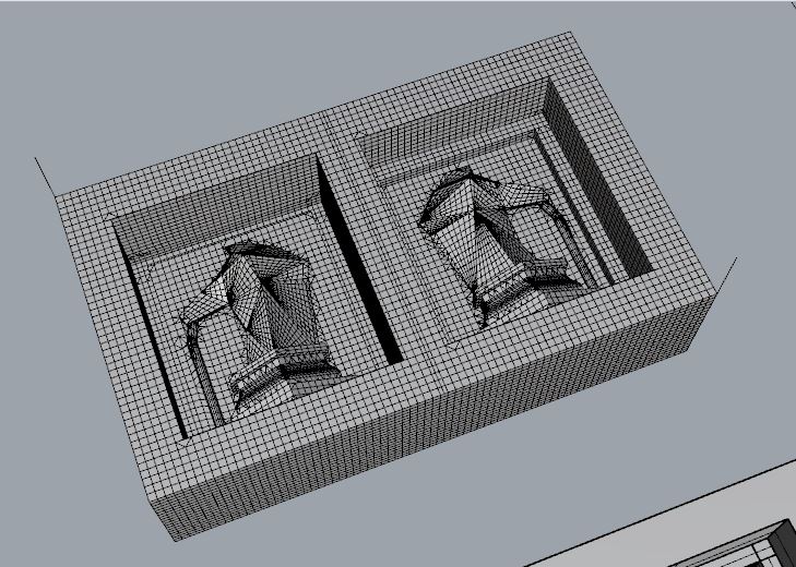
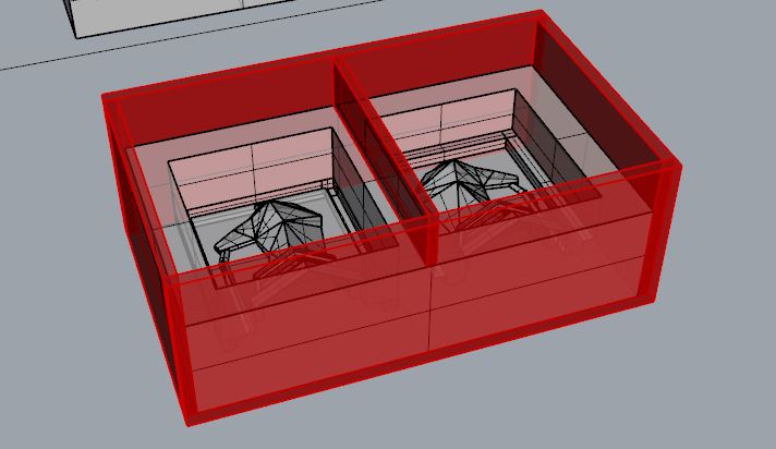
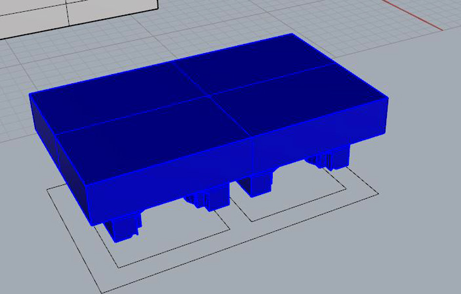
Once finished, my instructor and me had a look to the last version of the mould and we thought it would be best to have a larger joint. The cubes that substituted the previous spheres for joining one piece with the other are not enough to keep both parts together. Therefore, we talked about having a joint just on the perimeter that fits perfectly one piece with the other.
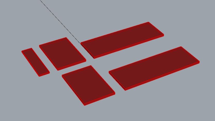
In this first picture, we can see the new joint on the mould's design. In the second one, the negative silicone mould + its volume. The last picture the final mesh..