*FINAL*PROJECT: RESULTS
INDEX:
- 3D design and structure:
- Structure in laser machine: Box, Ribs and Vertebrae.
- Structure in 3D printer: Tail, Head and Wheels - Input and Output:
- Phototransistor sensor.
- Dc Motor. - Programming:
- Arduino programming.
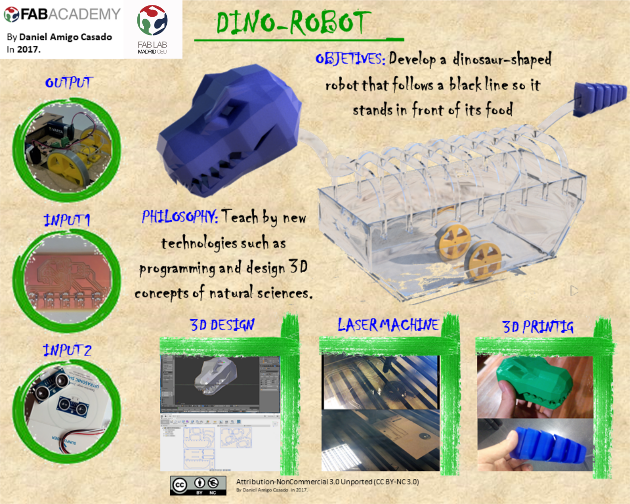
3D design and structure:
STRUCTURE IN LASER MACHINE: BOX, RIBS AND VERTEBRAE.
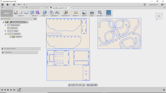
The structure of my dino-robot is composed of one side of a box that will be constructed by means of different methacrylate plates in the laser cutter, using Fusion 360 to do the parametric design shown below.
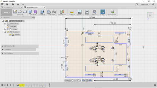

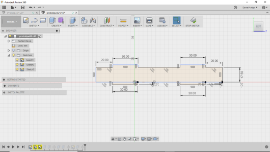
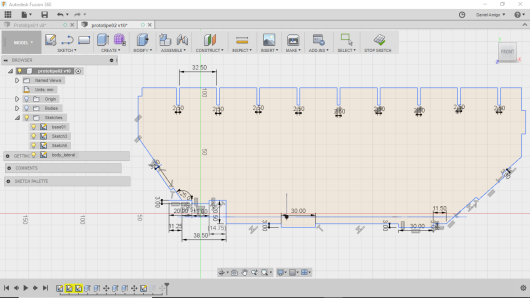
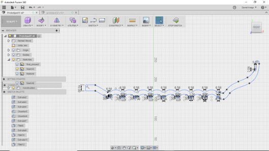
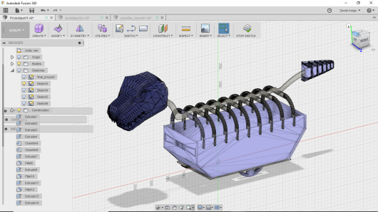
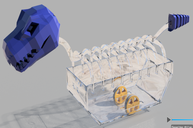
 Finally this design will render it together with 3D printing elements to give me an idea of how serious it would be. In the final robot I did not put all these structures, because it is a bigger project that needs more time and manipulation.
 For cut in methacrylate in the laser cutter machine the parameters were:
- Speed: 16
- Power: 20
- Corner power: 25
- Kerf: 0,15 mm
STRUCTURE IN 3D PRINTER: TAIL, HEAD AND WHEELS.
Make 3 elements printed in 3D:
- The dinosaur head.
- The dinosaur tail that you can find in week 5.
- And the wheels.
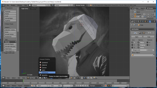
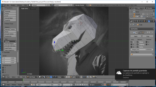
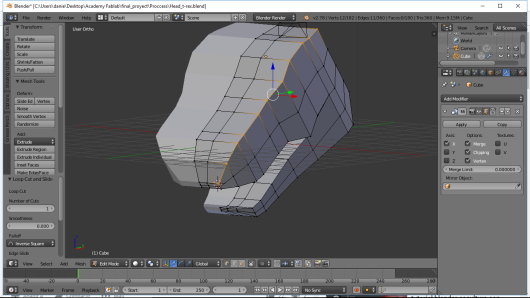
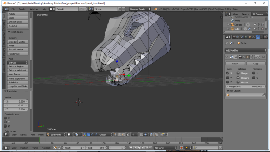
The design of the head model of Tyranosaurious rex was in Blender, for the design I took as a model the image of Wintercroft , for the design look for a simple but characteristic object being a Lowpoly dinosaur head. The development mode was from a box making face extrusions and body cuts. For the teeth was a translation of a vertex.
 This head I printed in 3D with a striking size and with a cleft in the back to hook with the methacrylate spine. Use a printer maker R2, with PLA.
The parameters that I used were:
This head I printed in 3D with a striking size and with a cleft in the back to hook with the methacrylate spine. Use a printer maker R2, with PLA.
The parameters that I used were:
- Temperature: 210ºC
- Layer Height: 0.20 mm
- Infill: 5%
- Raft: yes
- Support: No
Another structure printed with the same material, but designed in 123D design was the dino-robot tail, this tail is exclusively cast for 3D printing and you can see the process in week 5.
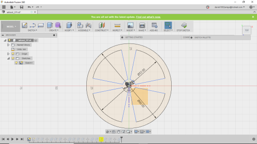
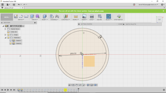
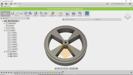
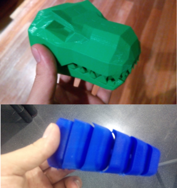 Finally, design the 360 dino-robot fusion, to print them and hook them to the axis of the engines, the kerf used was 0.20 mm. In order to increase the friction and grip to the ground I added an elastic PLA cover, ninjaflex. For this material the parameters that were changed were filament velocity and retraction parameters.
Input and Output:
PHOTOTRANSISTOR SENSOR.
For this final project I managed to use one of the two inputs, that of the phototransistors, which will be in charge of recognizing a line to be able to follow it through the movement of the motors.
For this I followed this process.
- Selection of components.
- Plate design in Eagle.
- Cut the plate and weld.
The components used were:
- ATmega168 x1
- Res 0 ohm x2.
- Res 10K x1
- Cap 1uF x1
- Resonator of 8MHz
- Phototransistor IR x5
- Res 100 omh x10
- Led IR x5
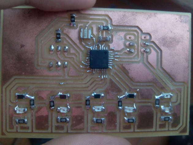
To create this plate of inputs use infrared phototransistors to be able to differentiate better between black and white, besides accompanying them with the infrared leds to be able to increase the difference between the values. Despite the use of 5 infrared, the main programming is only for two infrared. These infrared positions 2 on the right side, one in the middle and two on the left side.
For the design I also added a 2x3 and 2x2 headset to be able to program it by ISP and connect it to the serial bus connection. Design it in Eagle and modify the images in Inkscape.
 To cut the plate use a milling machine and use the following cut and cut files in order to use fabmodules and cut it.
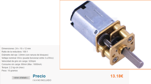
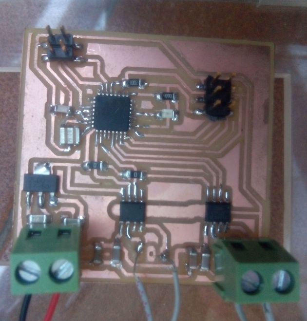
DC MOTORS.
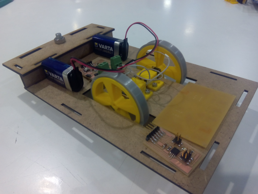
I used dc motors to move a robot about 1.5 kilos.
For this I followed this process.
- Selection of components.
- Plate design in Eagle.
- Cut the plate and weld.
The components used were:
- ATmega168 x1
- Res 0 ohm x2
- Res 10 K x1
- Cap 1 uF x3
- Regulator 5V1A
- H-bridge-A4953 x2
- Capacitator 22uF x2
- Capacitaror 10uF x2
- Blue led
- Resistor 499 omh.
- Resonator of 8MHz
- Motores DC with reducer x2
All the components that are shown here, it is in the inventori except for the engine, because it needed a motor that without being very big and without spending much could move more than 1 kilo of weight. The link is HERE.
I also put a 3x2 pin header, for the ISP connection and another 2x2 for the serial bus connection. In addition to 3 connectors for both motors and for supply power, that for all tests use a charger to light.
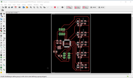
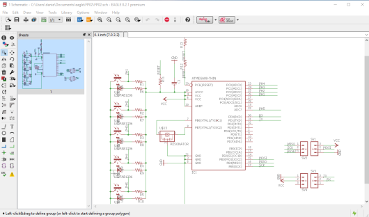
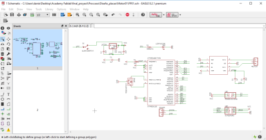
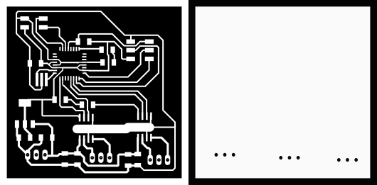
 For the design of the output plate use the base that had it of the week 09 and modify it like model like a motor more with its bridge H and to remove the switch to him. Do it in Eagle with the rules you can find in week 03. Keeping this schematic and this board.
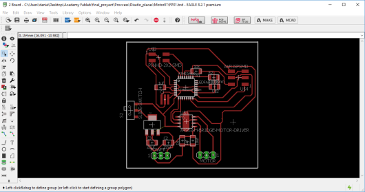
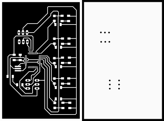
 Use the milling machine to cut the plate, using Fabmodules and loading the PNG of cut and cut that are shown below.
Programming:
ARDUINO PROGRAMMING:
The programming for this dino robot, is based on a connection between two plates with connection Rx and Tx crossed. The programming was in Arduino where you use conditionals, arrays and the monitor series.
The first programming that I made was the one of the sensors to be able to test the values that I needed, in this way I decided to do an average of 30 values in each sensor and if that value is greater of 500 it will be a black color, whereas values smaller than 500 will be A white color. So the programming for a white line remains.
int sensorMid = A1 ;
int sensorRight = A2;
int sensorRight2 = A3;
int sensorLeft = A0;
int sensorLeft2 = 7;

int lectura1 = 0;
int total1 = 0;
int media1 = 0;
int lectura2 = 0;
int total2 = 0;
int media2 = 0;
void setup() {
   Serial.begin(9600);

}

void loop() {

  for(int i=0; i<30;i++){
    lectura1 = analogRead(sensorRight);
    total1 = total1 + lectura1;
   }
  media1  = total1 / 30;
  if(media1 <=500){
  Serial.println('a');
  delay(10);
  }

  total1 = 0;

    for(int i=0; i<30;i++){
    lectura2 = analogRead(sensorLeft);
    total2 = total2 + lectura2;
   }
  media2  = total2 / 30;
  if(media2 <=500){
  Serial.println('b');
  delay(10);
  }

  total2 = 0;
}
This programming has three options: to follow straight that is by default in the programming of the motor, to guide to the right that happens when the letter "a" is printed and to turn to the left if "b" is printed in the series monitor. This would be the programming of the motors for the response to the reading of the parameters of the serial monitor.
 int in1Motor1= 5;
int in2Motor1= 6;
int in1Motor2= 9;
int in2Motor2= 10;
int encendido =0;
void setup() {
  // put your setup code here, to run once:
pinMode(in1Motor1,OUTPUT);
pinMode(in2Motor1,OUTPUT);
pinMode(in1Motor2,OUTPUT);
pinMode(in2Motor2,OUTPUT);
Serial.begin(9600);

}

void loop() {
  // put your main code here, to run repeatedly:

  analogWrite(in1Motor1,22);
  analogWrite(in2Motor1,0);
  analogWrite(in1Motor2,20);
  analogWrite(in2Motor2,0);
  if(Serial.available()){
    encendido= Serial.read();

    if(encendido== 'a'){
  analogWrite(in1Motor1,62);
  analogWrite(in2Motor1,0);
  digitalWrite(in1Motor2,HIGH);
  digitalWrite(in2Motor2,HIGH);
 //Serial.println('a');
  delay(3);
    }

    else if(encendido== 'b'){
  digitalWrite(in1Motor1,HIGH);
  digitalWrite(in2Motor1,HIGH);
  analogWrite(in1Motor2,60);
  analogWrite(in2Motor2,0);
 //Serial.println('b');
  delay(3);
}
 }
FILES:- dxf laser
- project fusion 360
- 3D tail object
- x3g tail object
- Traces Master
- Interior Master
- schematic input
- Board input
- Traces motor
- Interior motor
- schematic motor
- board motor
- Dino head
- Project wheels fusion 360
- programming sensors
- programming dc motors