Fabacademy 2017
Sixth Week. Electronics design
Index
Sixth task
Redraw the echo hello-world board
This week task is to redraw the hello-world board using a circuit board design software. Then, add a LED and a button switch. Finally, mill the board, solder the components and test it.
Autodesk Eagle. Drawing the schematic
I didn't have plenty of time this week to experiment with different softwares so I decided to concentrate my efforts on learning Autodesk Eagle. I will try others for the next electronics lessons. As it is freeware and one of most used softwares for hobbyist there are plenty of tutorials on internet. I would recommend This series in Sparkfun.
It is good to have a good reference about components and their polarity. I found this short and simple article on Sparkfun again.
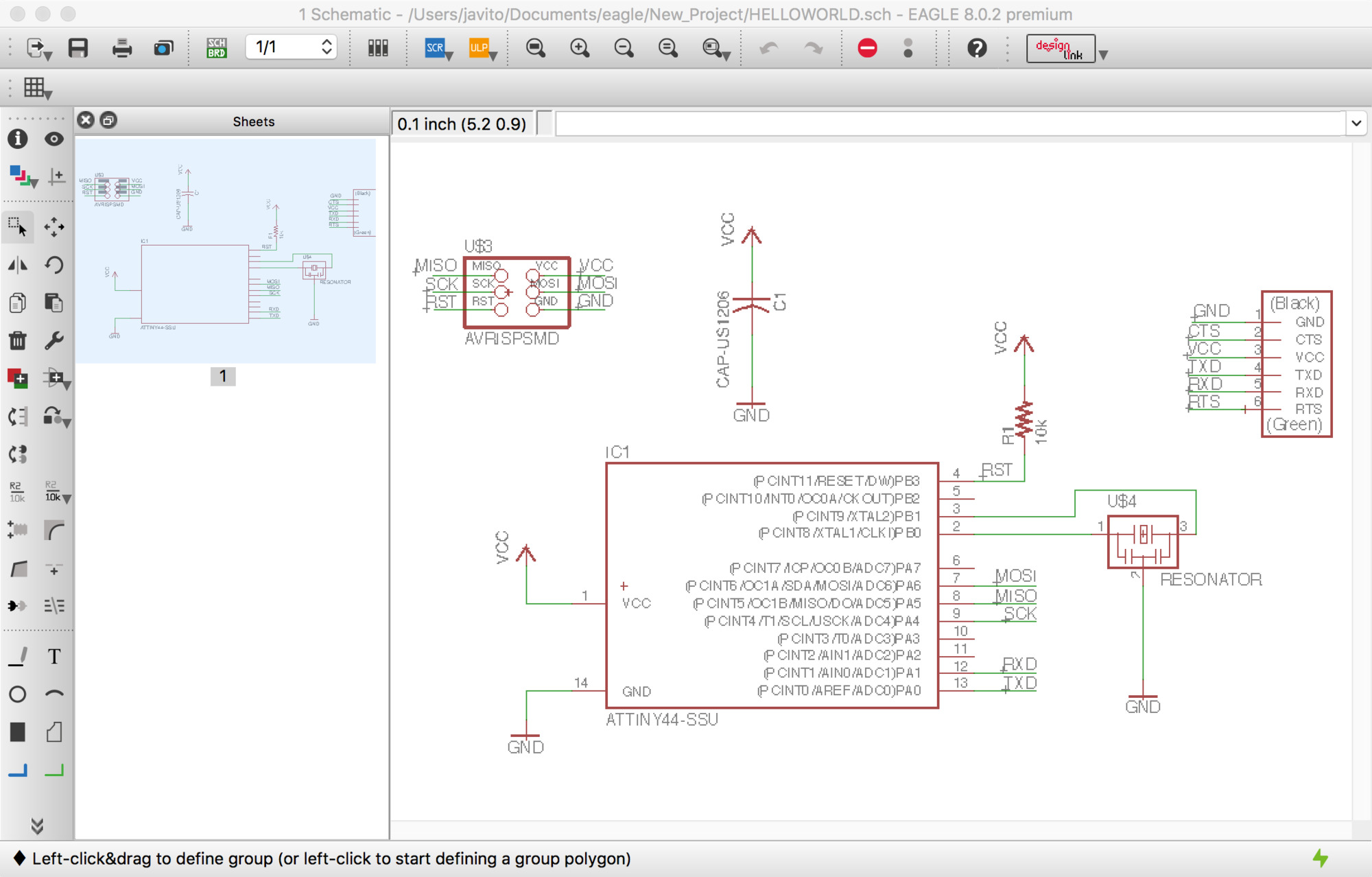
Before drawing the schematic you need to make sure that you have the right libraries installed in Eagle, the hello-world board uses the fab library and the supply library included by default on the Eagle installation. Once the libraries are installed, the process of redrawing the board is quite straight forward:
- Place the components
- Label the components and assign the value for resistances and condensers
- Wire the components
- Label the wires
If wires are labeled correctly the software will automatically connect all these different areas together. For now, I just followed the existing schematic, I imagine that as long as you learn more about how to design your own circuits, the logic on how a schematic is structured will become more and more evident.
Being used to cad and graphic design tools were it is very simple to align, modify and group objects, Eagle GUI felt not very user-friendly, I can understand why coding instead could be more enjoyable, would need to try other software choices.
Board layout
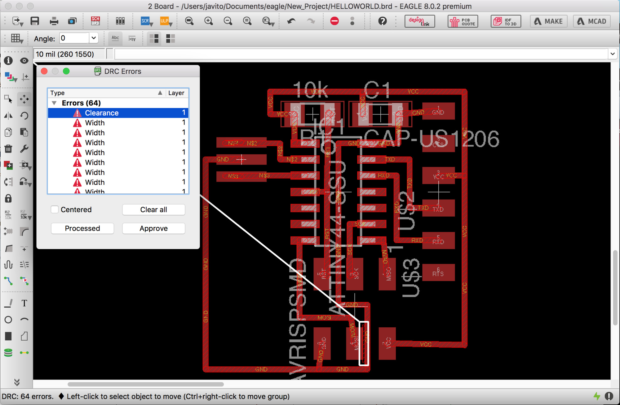
When the schematic is finished you need to switch to the board layout view, in this view the components and traces are displayed with its physical footprint so we can start arranging then together in the desired board boundary. Distances and sizes are critical for milling, placing and soldering the components so this is a skill that needs time to be developed adequately.
For this reason, adjusting the design rules to the manufacturing technology that will be used it is a crucial step.
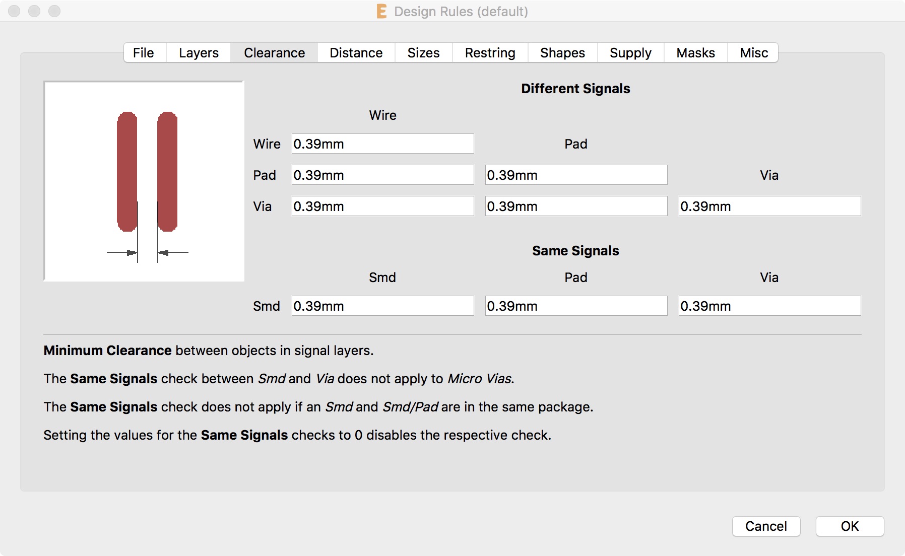
For milling the board with the Roland MDX-20 Using 1/64 inch (0.396mm) bit for the routes and 1/32 inch (0.793mm) for the outline, the following parameters need to be considered:
- Clearance: is the space between routes and components pads. Minimum value should be our smaller bit so the mill will be able to do at least one path between elements.
- Distance: is the minimum space between the board boundary and the routes, I had problems with this setting as I forgot to draw my board boundary on layer 20.
- Sizes: these are the minimum sizes of our signal layers elements. As a rule of thumb it should be at least our biggest bit (1/32 inch) but this would vary of the circuit design itself as some circuits will require wider or thinner routes.
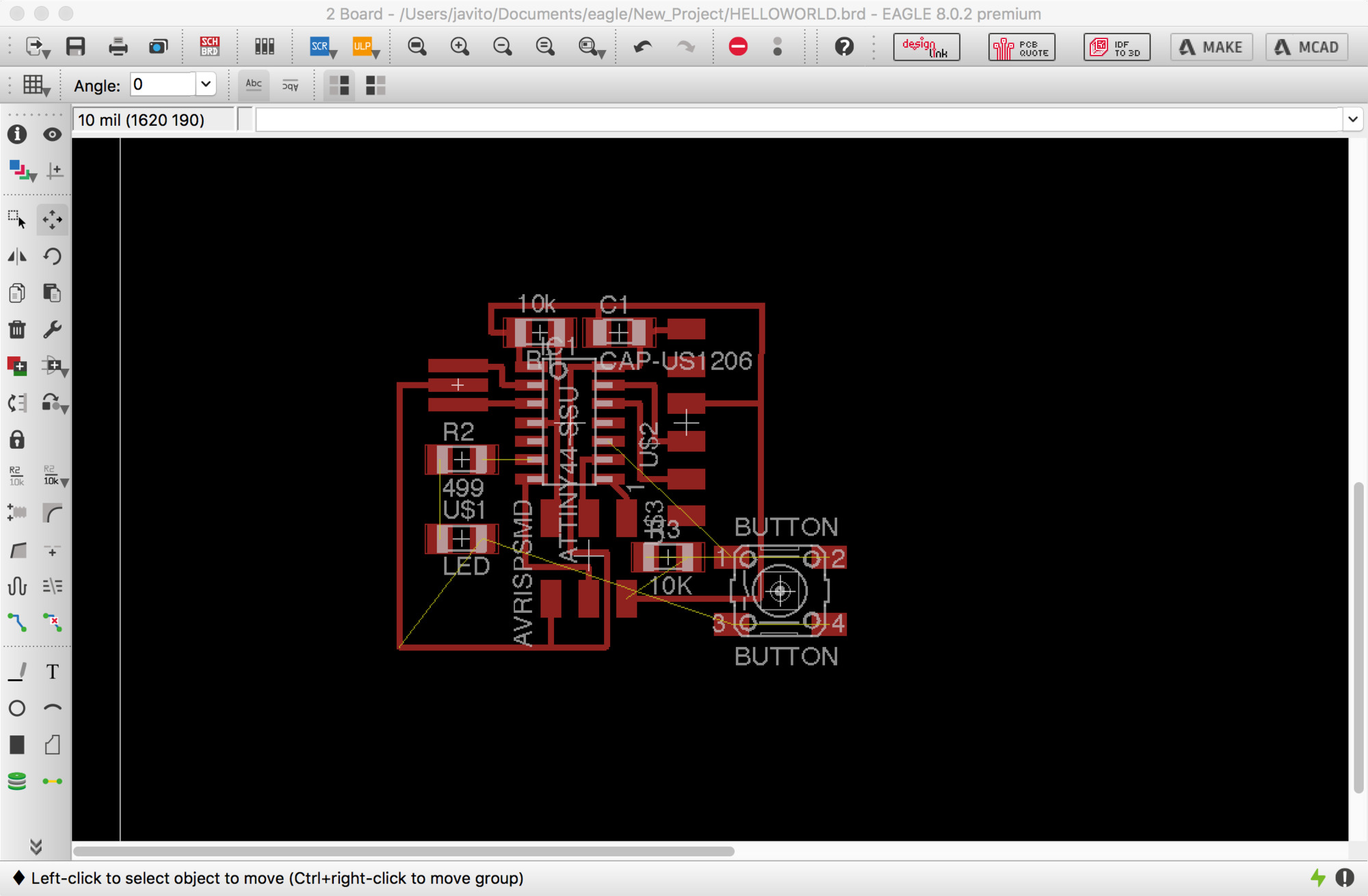
Adding a button and LED
Once the basic board is drawn and there are no errors when checking my design rules, I added the requested button and LED. As it was explained in the class, you always need to limit current into a LED, there are plenty of resistor calculators out there but as I was using the same LED than in the first board I simply choose the same resistor that it was used on the Attiny board 499 ohms. The tutorial recommended to place a 10k pull-up resistor the button but later I learned that pin 6 utilizes the internal 10k pull-up resistor of the Attiny44 so it is not really necessary.
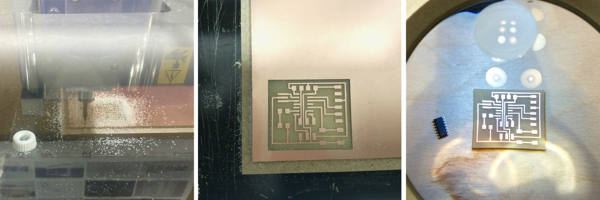
Milling the board
The process for milling the board is to generate a PNG file from Eagle using the Export>Image dialogue in the menu. Resolution should be set at 1200ppi. Do not forget to switch off all the layers but number 1 "Top" and make sure that monochrome is checked in the import dialogue.
I found a bug on the Mac version of Eagle v.8.0.1: When you import the image in a retina screen Mac, Eagle will double the size of pixels of your image without notice, leading to a x2 size of your board so be careful! You will need to scale down 50% your image in Gimp or Photoshop. Once I got the correct size image, I added a 2mm border that I used to create the outline .PNG for cutting the board after milling.
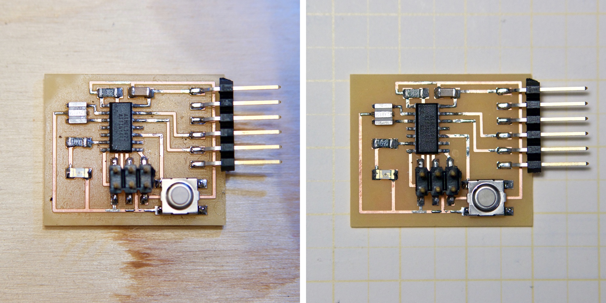
Soldering components
Soldering went smoothly, I actually find it quite relaxing and think I am getting better but as pictures show there is still a lot of room for improvement. I havent managed yet to remove the occasionally solder spots on the routes when I accidentally touch the copper with the solder tip.
Also, the board might need some redesign as some of the components were harder to access with the solder tip –I didn't pay attention to the relative heights of each component which make harder to access them with the solder tip–
Programming and testing the board
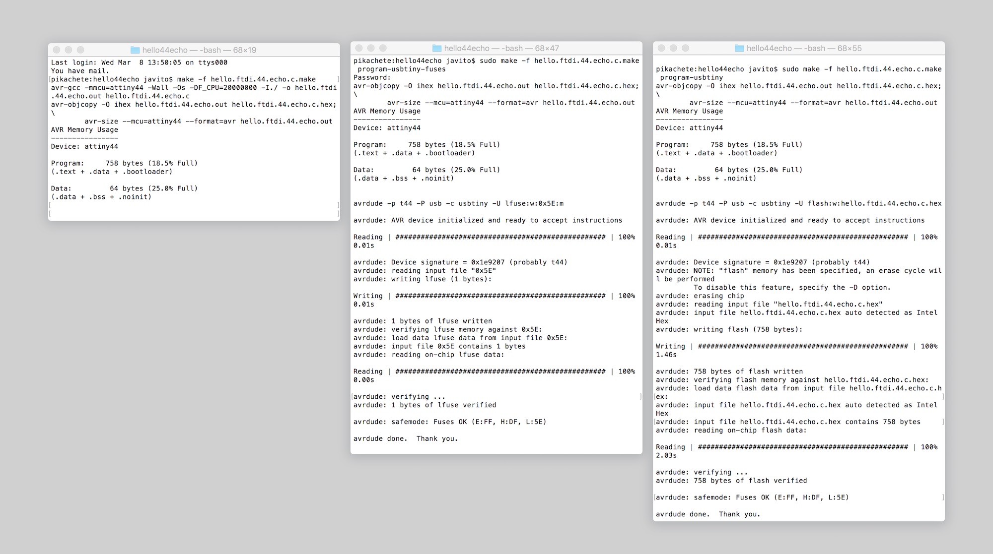
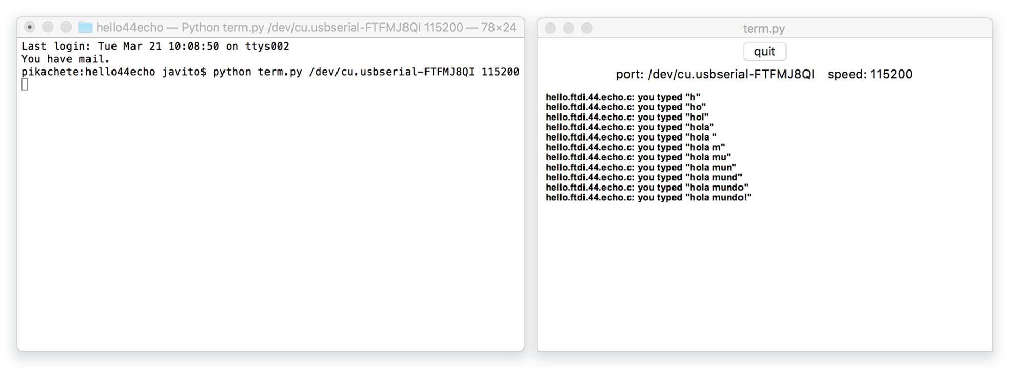
I followed the steps provided in this tutorial. Compiling the C program, sending the fuses and flashing the board with my FabTinyISP, everything worked as expected.