Fabacademy 2017
Fourth Week
Fourth lesson
Electronics production
Fourth lesson was on electronics production. We covered the most used methods: etching, which used chemicals and photographic processes hence most suitable for large batches of boards, and milling perfect for prototyping and manufacturing small quantities.
Using a bitmap to design and draw circuits was a surprise for me as I always thought that you would need rather sophisticated tools to design and mill circuits. Using Antimony in the third assigment was also an eye opener on this matter as I realized that you just need a tool that outputs high-res bitmaps to control CNC's, milling machines or laser cutters.
Circuit milling and surface mount soldering were explained in detail. Never did any of them before so I was pretty excited to get started.
Fourth assigment
Building the FabTinyISP
I am doing Fabacademy at Fab lab Madrid CEU but I am based 400km south from Madrid so time at the Fab Lab CEU is limited and I have to make the most of each of my visits. Because of that, I didn't have the chance to mill the board myself so I got a preexisting milled board and all the components to work on the assignment once I was back in Córdoba. Next time, the plan will be to mill a customized FabTinyISP and program with the one I made this week.
UPDATE: Milling the board
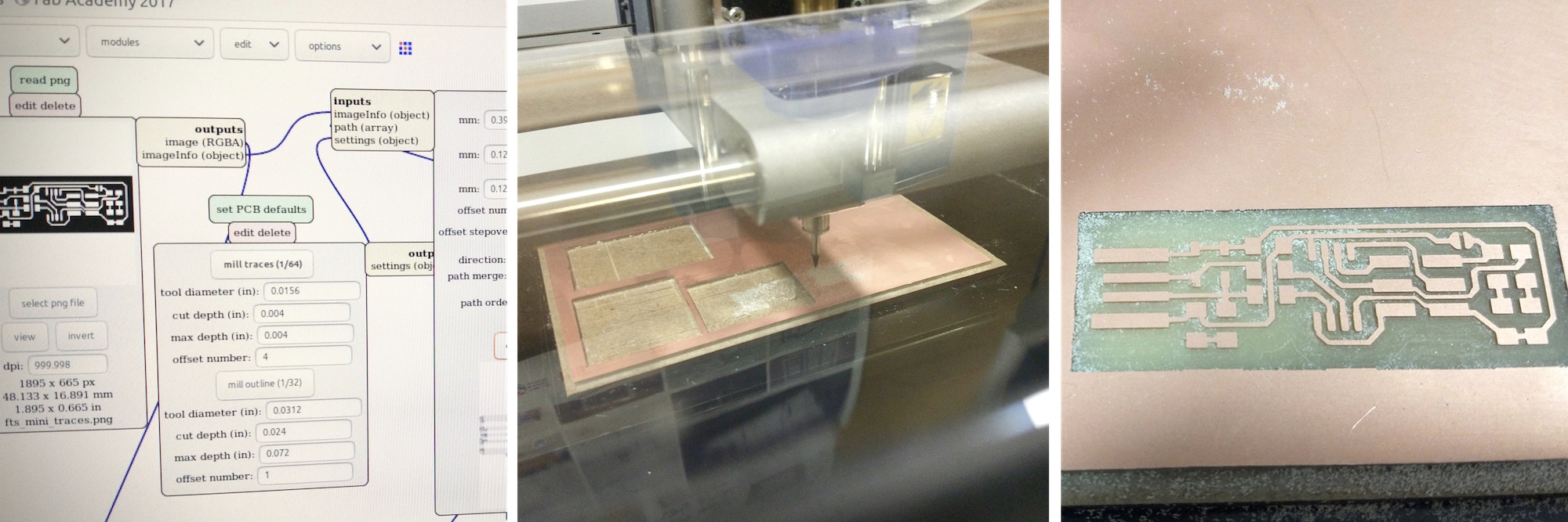
I finally had the chance to mill the FabTinyISP board myself. Process worked out without major issues. I got existing board layout and outline in .png and Fab Mods connected to the Roland MX20. The 1/64 bit was a slighty worn out at the tip so I was advised to increase the cut depth 0.01mm to get a cleaner copper removal, I also set offet to 0 to revome all the copper ouside routes and pads.
FabTinyISP
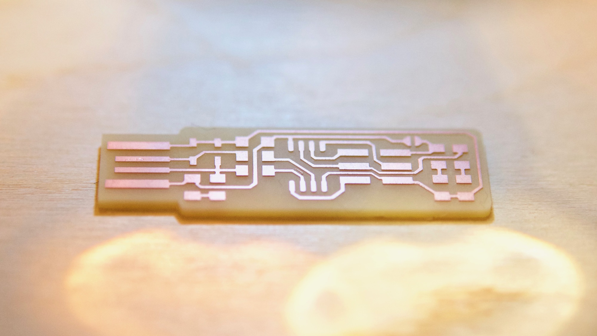
The FabTinyISP is one of the simplest available designs so it was perfect for a first timer like myself. Only 13 components for soldering and no tricky microUSB connectors. The complete manufacturing and programming process is described in all detail here
After watching a number of 101 surface mount soldering tutorials on YouTube repeatedly, I went to my local electronic shop to get the secret "sauce" that I did not know about before: Flux. Flux is a liquid that is inside soldering wire –never realize before that soldering wire was hollow!– which cleans the soldering areas, distribute heat and helps making a perfect bond. When doing surface mount soldering you put some soldering on the solder tip first so all the flux runs down far away from the component so it is important to have an extra bottle of flux around and apply it on top of the components before applying heat with the solder tip.
Surface mount components are tiny so keeping everything organized and clean is always a good idea. When I started laying down all the components and double-checking them in the diagram I realized that my attiny45 didn't look as expected, the component was roughly half the size and connectors were super tiny! First thing that I assumed was that I was given a complete different component but after doing some research I realized that components come in different packages –primarily PDIP for through hole, SOIC for surface mount big size and TSSOP for surface mount small size– and that I have got a attiny45 in TSSOP package rather than SOIC.
Right then I though that the mistake would prevent me for finishing the assignment on time as I was back in Cordoba and 400km far away from the Fab Lab!
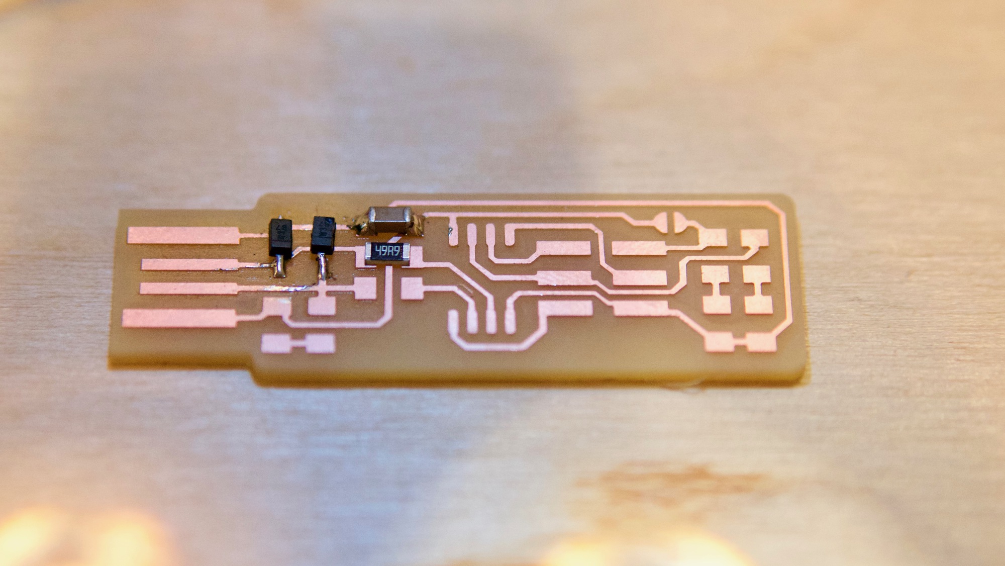
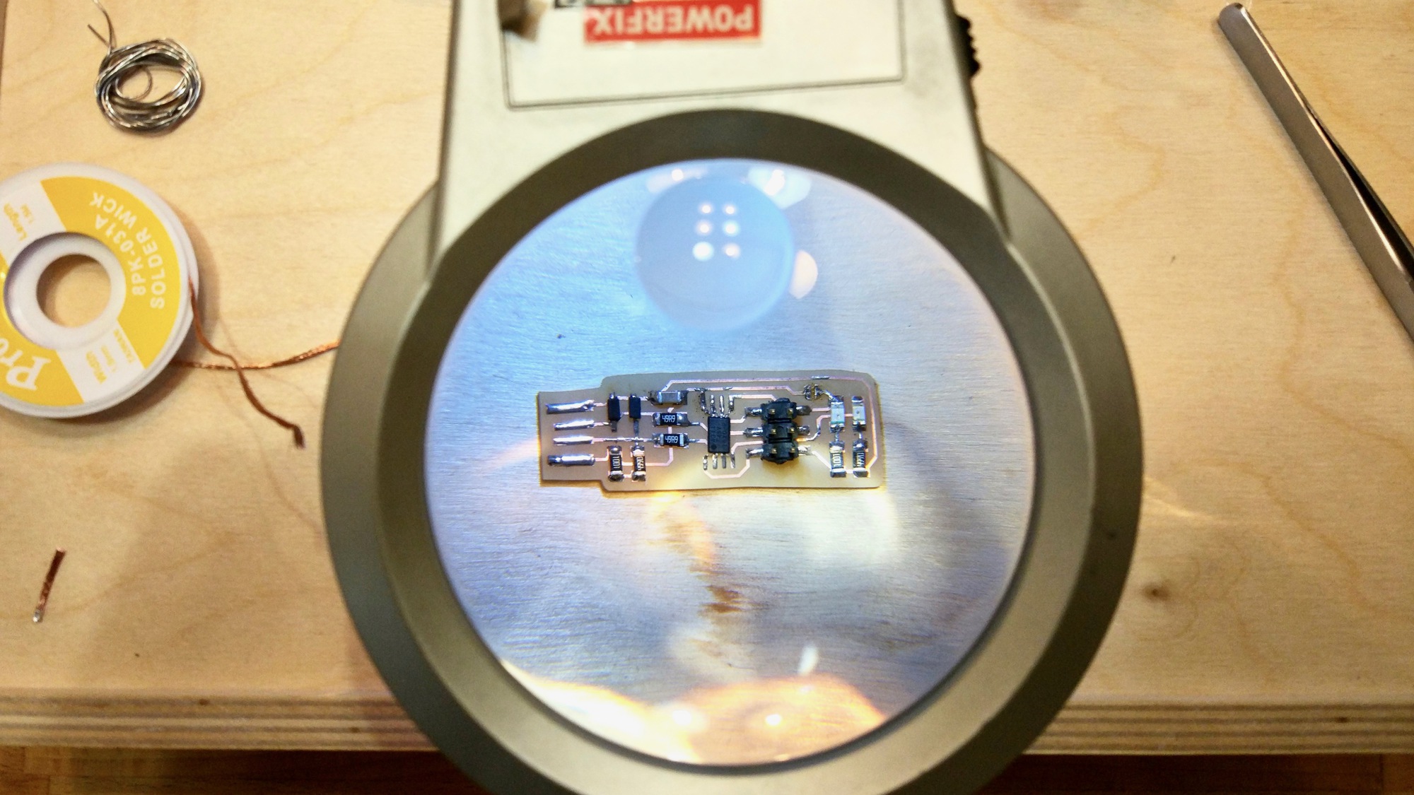
I started soldering the other components to the board, at least I could document part of the assignment. Soldering was much more enjoyable than I though it was going to be, it takes some practice but I find it extremely relaxing. In a couple of hours the board was finished waiting for an attiny45 SOIC.
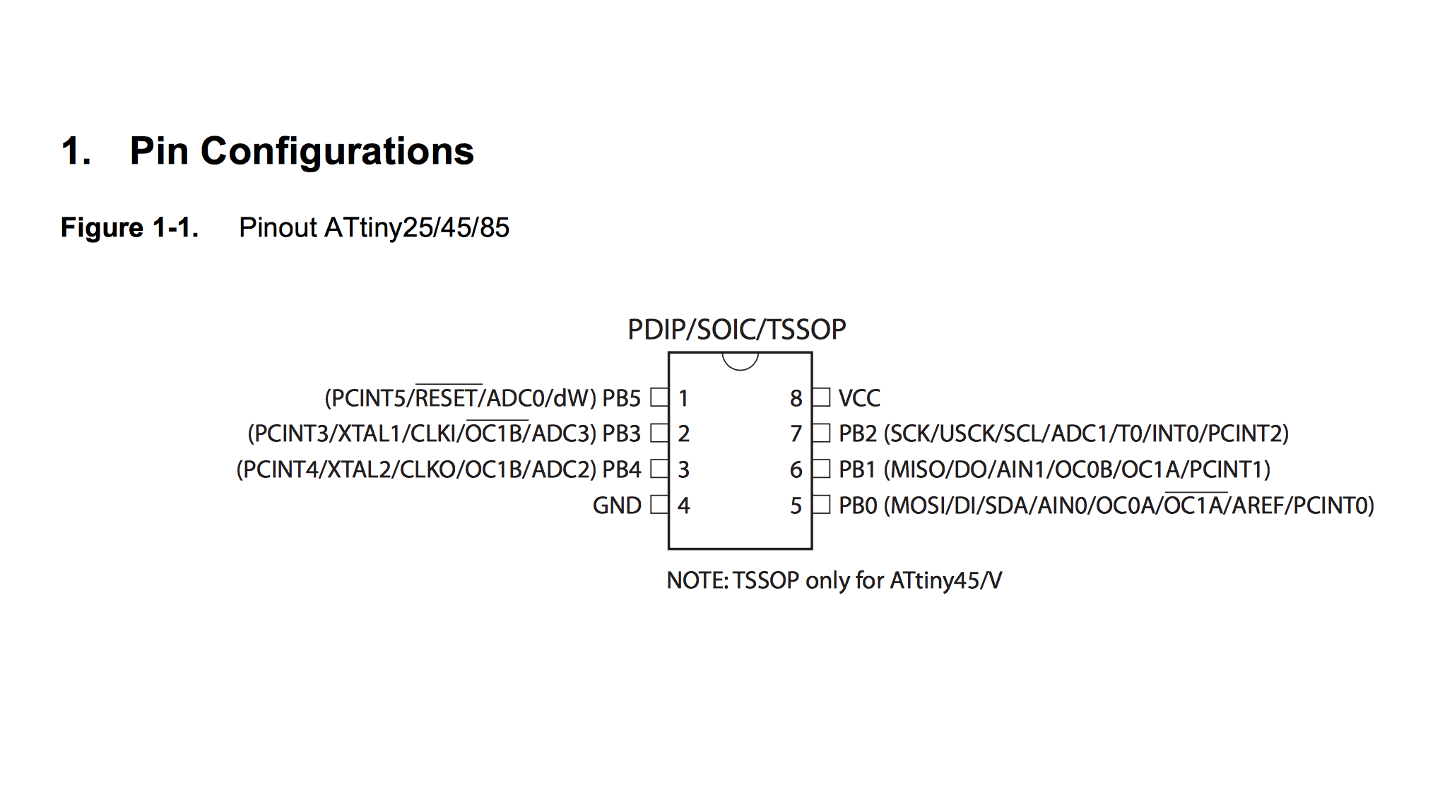
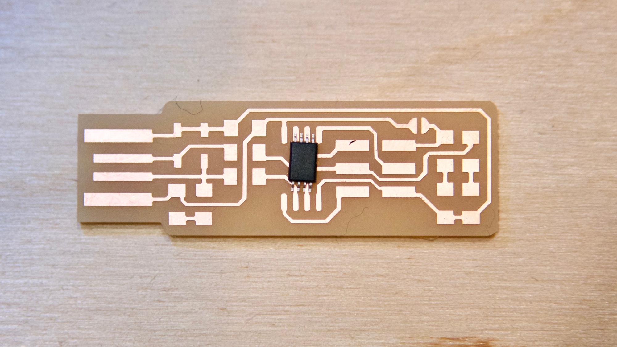
I had build confidence on my soldering skills so I thought that maybe I could bend the tiny legs of the TSSOP chip and connect them to the pads with some extra solder. But first I had to check if different packages meant different leg orientations. Atmel website provided all the technical specs for the chip
It seems that they were exactly the same connectors just half the size! So I went back to the desk grab a pair of extra tweezers and patiently bent each connector stretching the chip as much as possible. 45 minutes later the attiny TSSOP looked like a smashed bug in my FabTinyISP, I double-checked that there were no short circuits with a loupe and I hoped for the best.
Programming the FabTinyISP with an Arduino
As the assignment was being done far away from the Fab Lab, I didn't have access to a commercial programmer, luckily there is plenty of information on Internet on how to use an Arduino Uno as an ISP.
This process wasn't linear at all and I had to go back and forth few time to get everything working. In the Building the FabTinyISP website, it is not explained how to program it using an Arduino so I followed this tutorial to fully understand how to use an Arduino, although in the instructables tutorial they just program the attiny with a blinking led demo but not to be used as a programmer itself. The basic steps are:
- Upload the right ArduinoISP program onto the Arduino
- Build a six pin cable and wire the FabTinyISP pin connector with the Arduino io pins
- Connect the Arduino to the computer via USB
- Download the right firmware for the FabTinyISP
- Compile the firmware
- Program the FabTinyISP
Notes and recommendations:
- I used a MacBook Pro with MacOS 10.12.3 and the latest XCode installed
- Make sure that you have installed the last version of avrdude, I used 6.3 installed via homebrew
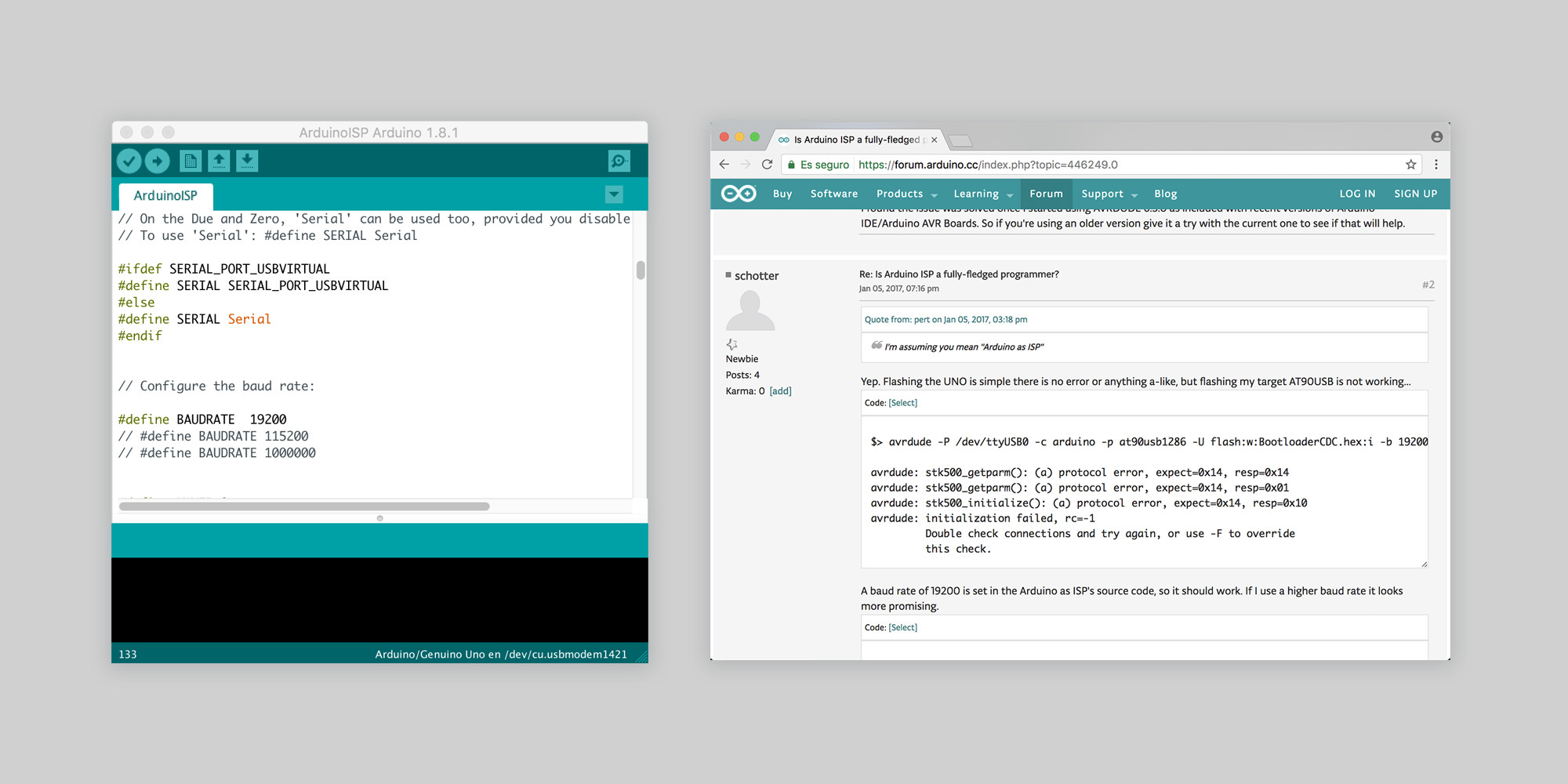
- Don't use the ArduinoISP example from the Arduino IDE, use the Adafruit version instead
- Use the firmware downloaded from the Building the FabTinyISP website, mine was fts_firmware_bdm_v1
- I needed to make a couple of adjustments to the makefile, MCU should be attiny45 and programmer arduino.
MCU = attiny45
PROGRAMMER = arduino
Finally, you need to make sure that the baud rate and port settings are correct when running the Makefile. In my case the baud rate was set at 19200 in the Arduino script so I have to set up the same rate in avrdude -b 19200. The port correct settings will depend if you are using mac, linux or windows but it is very easy to double-check in the Arduino IDE Menu>Port, then use the same port in avrdude -P /dev/cu.usbmodem1421
flash: all
	$(AVRDUDE) -p $(MCU) -c $(PROGRAMMER) -P /dev/cu.usbmodem1421 -e \
		-U flash:w:$(APPLICATION).hex -b 19200

fuses:
	$(AVRDUDE) -p $(MCU) -c $(PROGRAMMER) -P /dev/cu.usbmodem1421 \
		-U lfuse:w:$(LFUSE):m -U hfuse:w:$(HFUSE):m \
		-U efuse:w:$(EFUSE):m -b 19200
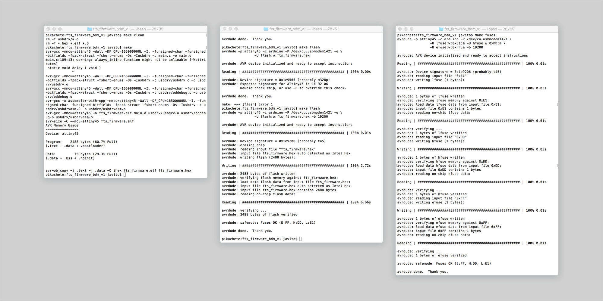
Once all this is ready, run make clean, make, make flash and make fuses. If everything goes as expected, messages should look like the following captures.
Before doing the last step will be checking that the FabTinyISP USB works in Apple System Profiler.
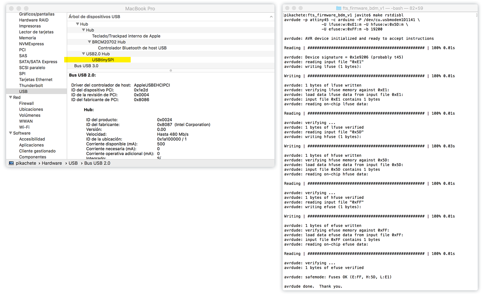
Blowing the Reset Fuse
We need to change the bit that turn the ATtiny45's reset pin into a GPIO pin. Note that this will disable our ability to reprogram this ATtiny45 in the future. After running make rstdisbl, avrdude will never be able to talk to this chip again through the ISP header.
Finally, we disconnect VCC from the Vprog pin on the ISP header by removing the bridge on the solder jumper. Our FabTinyISP programmer is ready!