Fabacademy 2017
Fifth Week
Index
Fifth task
3D Printing and scanning
This week's task was to start 3D printing and scanning and by doing so develop designs that take advantage of the unique characteristics of additive manufacturing. In additive manufactured objects, designers have great control on not only the boundary of the object but the structure of the 3D printed object itself. This opens up an unprecedented flexibility to transform the object’s strength-to-weight ratio or the position of the object’s center of mass for example.
I would like to explore the possibilities of additive manufacturing for certain components of my window project.
Metamaterials mechanisms
On my research on functional additive manufacturing mechanism I found This paper by a group of researchers –Alexandra Ion, Johannes Frohnhofen, Ludwig Wall, Robert Kovacs, Mirela Alistar, Jack Lindsay, Pedro Lopes, Hsiang-Ting Chen, and Patrick Baudisch– of the Hasso Plattner Institute in Germany about Metamaterials mechanisms.
Metamarials are artificial structures with mechanical properties that are defined by their usually repetitive cell patterns, rather than the material they are made of.
As the authors explain in the paper, the research explores the idea of considering metamaterials as machines rather than just materials by creating objects that allow for controlled directional movement. This allows users to create objects that perform mechanical functions.
FDM and stereolithography
I had access to two different 3D printers this week: First the Sharebot's Kiwi which is a low-end FDM printer with a printing volume of 100x100x140mm and without heated bed so it is mostly suitable for PLA and similar materials that adhere well to the base without the need of additional heat. Second, Formlabs Form2, a desktop stereolithography printer which is very simple to use and delivers an almost hands free experience with almost no learning curve to produce high quality results.
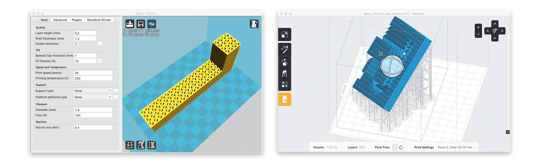
Softwarewise, for the Kiwi I used Ultimaker's Cura with Sharebot's custom .ini profiles, for the Form2 I used Formlabs own Preform software. In the last couple of years slicer and preparation software has improve dramatically and somewhat reflects the recent popularity and widespread use of desktop 3D printing.
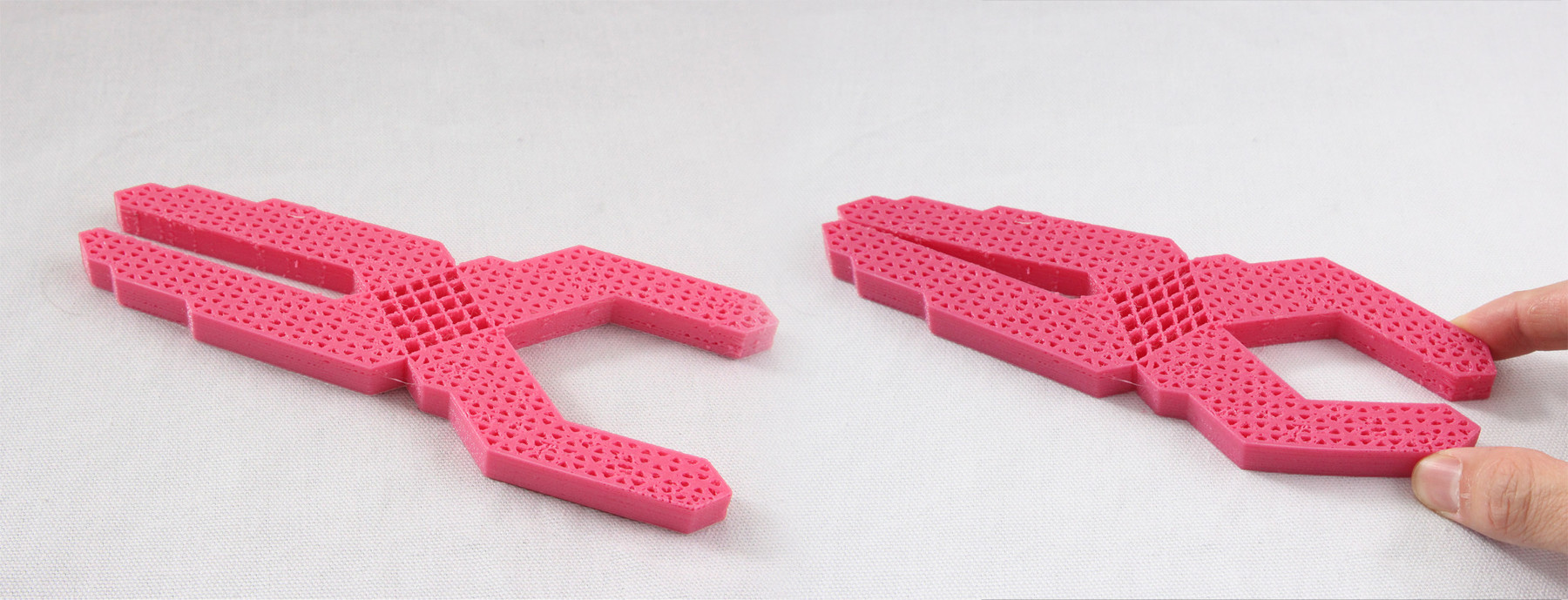
Printing a metamaterial latch mechanism
One of the published metamaterial mechanism examples was a door latch which I got very interested about as a variation of this design could replace the milled or cast metal hardware of my window. The paper promised a great strength and durability but in order to be sure I would need it to test it myself. So I planned to print a version on each 3D printing technology and test both.
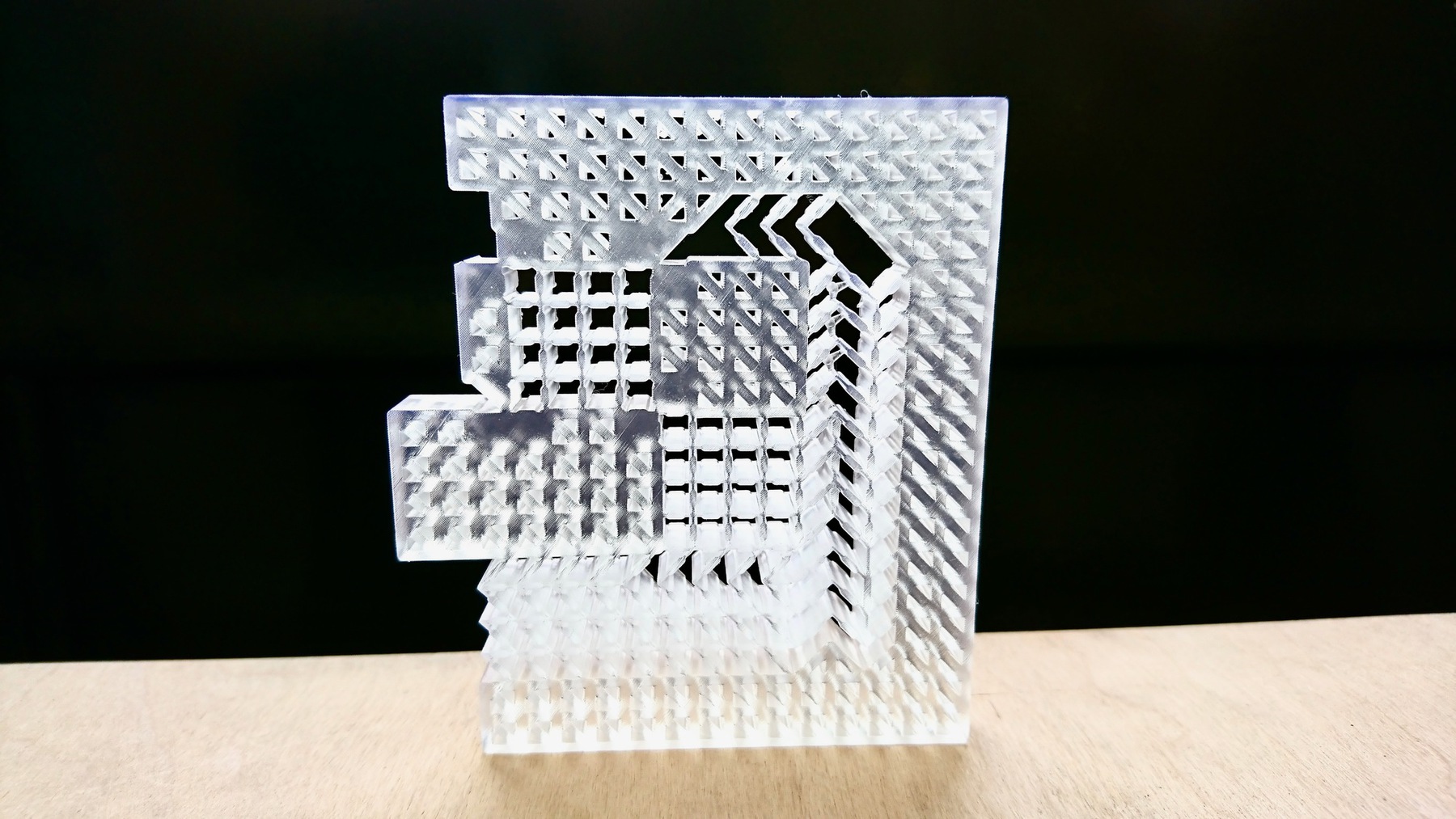
Unfortunately, in the case of the Form2 I didn't have any flexible resin. I have order some and I will be doing test in the following weeks. Meanwhile I printed a test on clear resin which is the only one that I have access to this week.
It is understandable the enormous hype that the Form2 has generated recently as they have managed to deliver a simple, reliable and affordable product. I am really looking forward to print with the flexible resin.
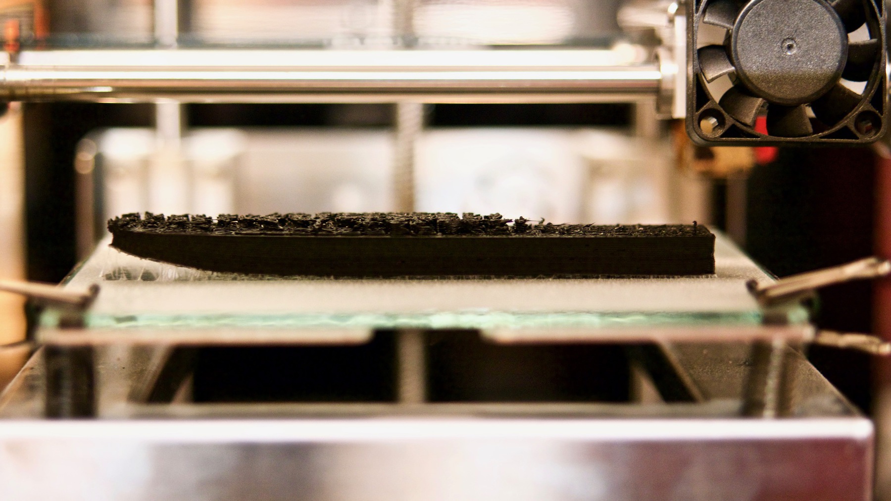
On the other hand FDM printing –despite machines have become very reliable– still requires plenty of fine tuning in order to get good prints. I used Ninjaflex which is one of the best know flexible filaments in the market, following carefully their printing guidelines:
| Extruder Temperature | 225°C – 235°C |
|---|---|
| Platform Temperature | Room temperature – 40°C Glue and/ or blue painters tape is suggested if not using a heated bed |
| Print Speed | Top and bottom layers: 10-20 mm/ sec (600-1200 mm/ min) Infill speeds: 15-35 mm/ sec (900-2100 mm/ min) Layer 2+ use cooling fan if available. |
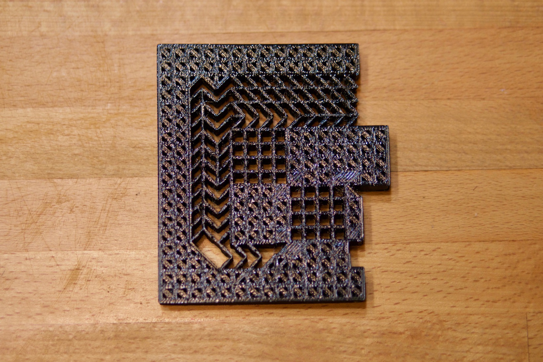
Results were not that good as to date I havent able to prevent yet a noticeable warping on the bottom side of the pieces. I believe that this is caused by the lack of a heated bed on the Kiwi's design, I tried to minimize this by spraying adhesive to the base which it worked ok on the larger surface prints but did not help much on prints with smaller surface contact.
Group task
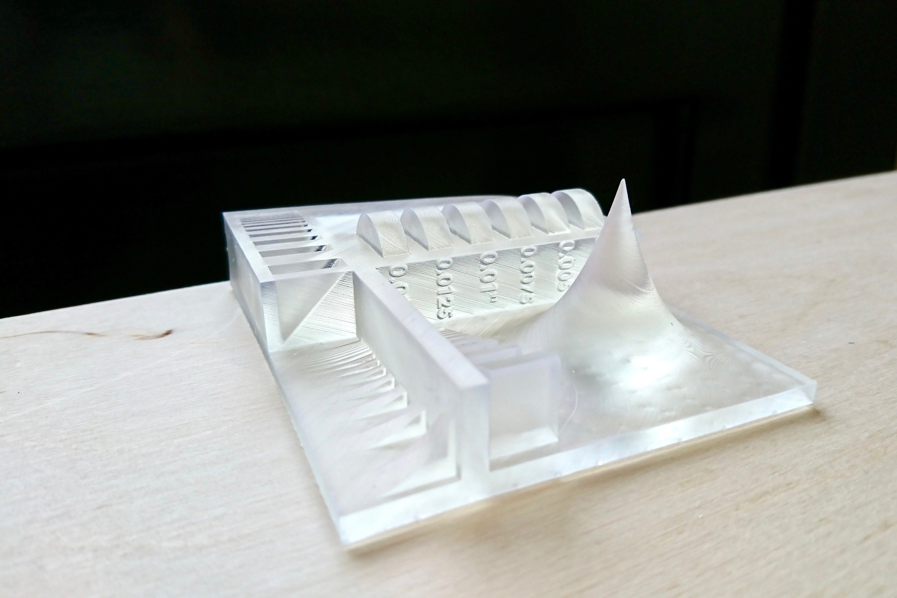
The group did test extensively the desing rules of the Makerbot which are described on the group page. My contribution on this page was to 3d print the test file in Fab Lab Limerick's brand new Form2 in clear resin. Stereolithography differs from FDM in many aspects but design rules are similar regarding overhangs and support structures. I followed excellent Formlabs documentation to optimize the printing process for flat surfaces and overhangs. I used a 0.1mm layer thickness for the quickest result.
The Form2 makes the whole process of preprocessing and printing really easy. In my experience the printing sucess rate is avobe 90%. The biggest downside is the reduced printing volume and the neccesity of cleaning and curing after printing.
Update on the 3D printing task
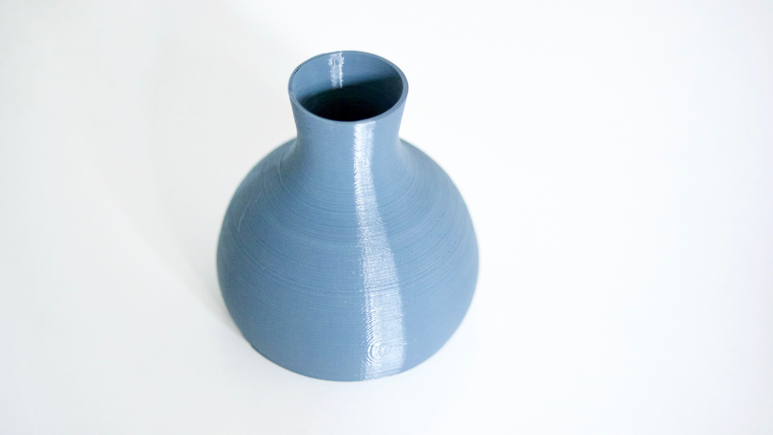
During one of our local reviews it was noticed that these type of mechanisms could be milled thus not making them appropiate for this week assigment. So I decided to design and print a hollow design which will fit the requirements. Using Onshape revolve tool, I designed a hollow vase with a thin neck that would be really hard to fabricate using substractive technologies.
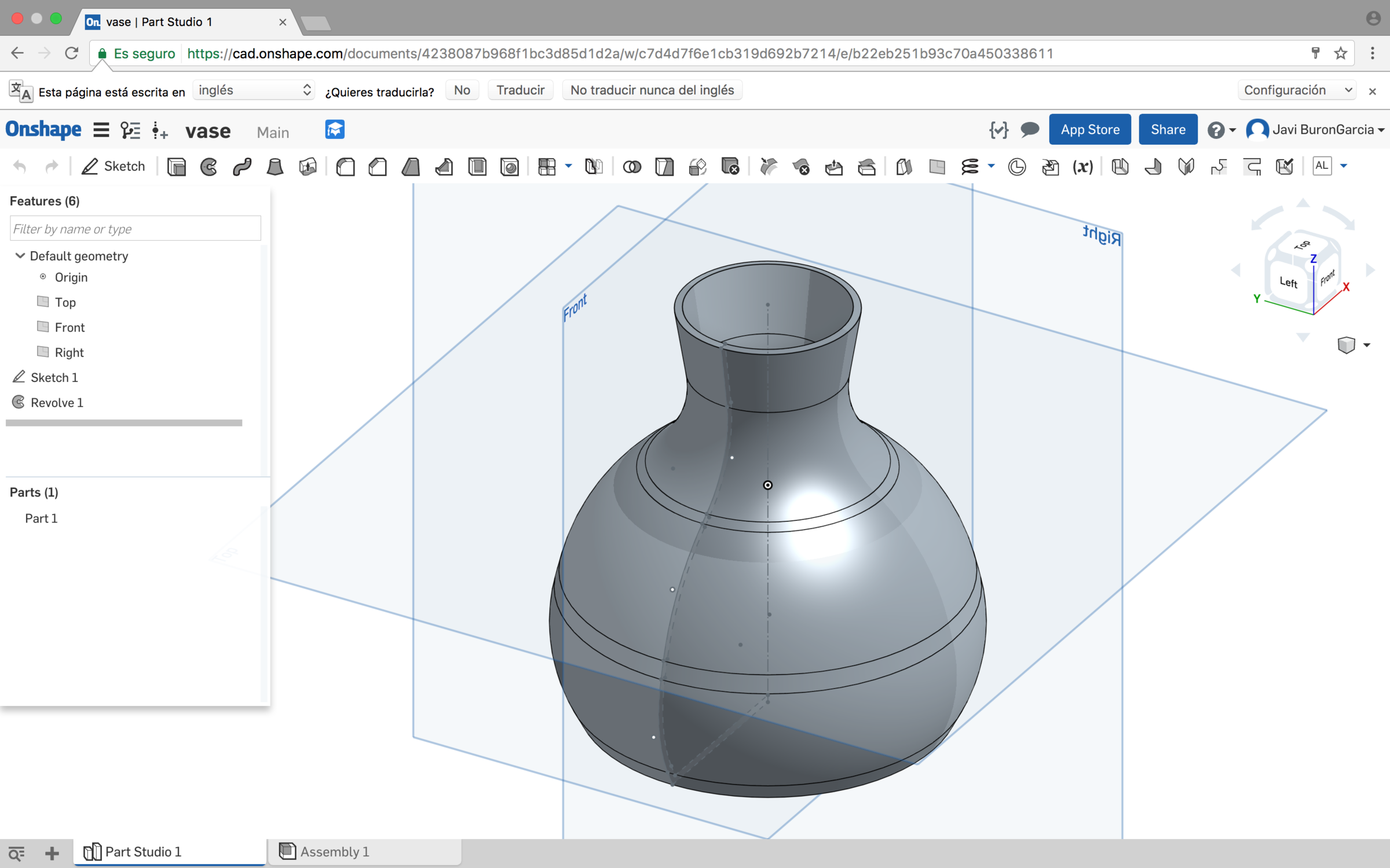
It is interesting to observe that the potter's wheel is in some way an additive manufacturing process compared with susbtractive process based on a rotating axis like the lathe so many shapes made with a potter's wheel are relatively simple to fabricate with FDM 3d printing and much harder to fabricate with a lathe.
Once the design was ready, I exported as a STL file, processed with Cura and printed it in bluegrey colorfab PLA 1.75 filamente using the following settings:
| Layer height | 0,1mm |
|---|---|
| Fill density | 100% |
| Print Speed | 100mm/s |
| Extruder temperature | 220ºC |
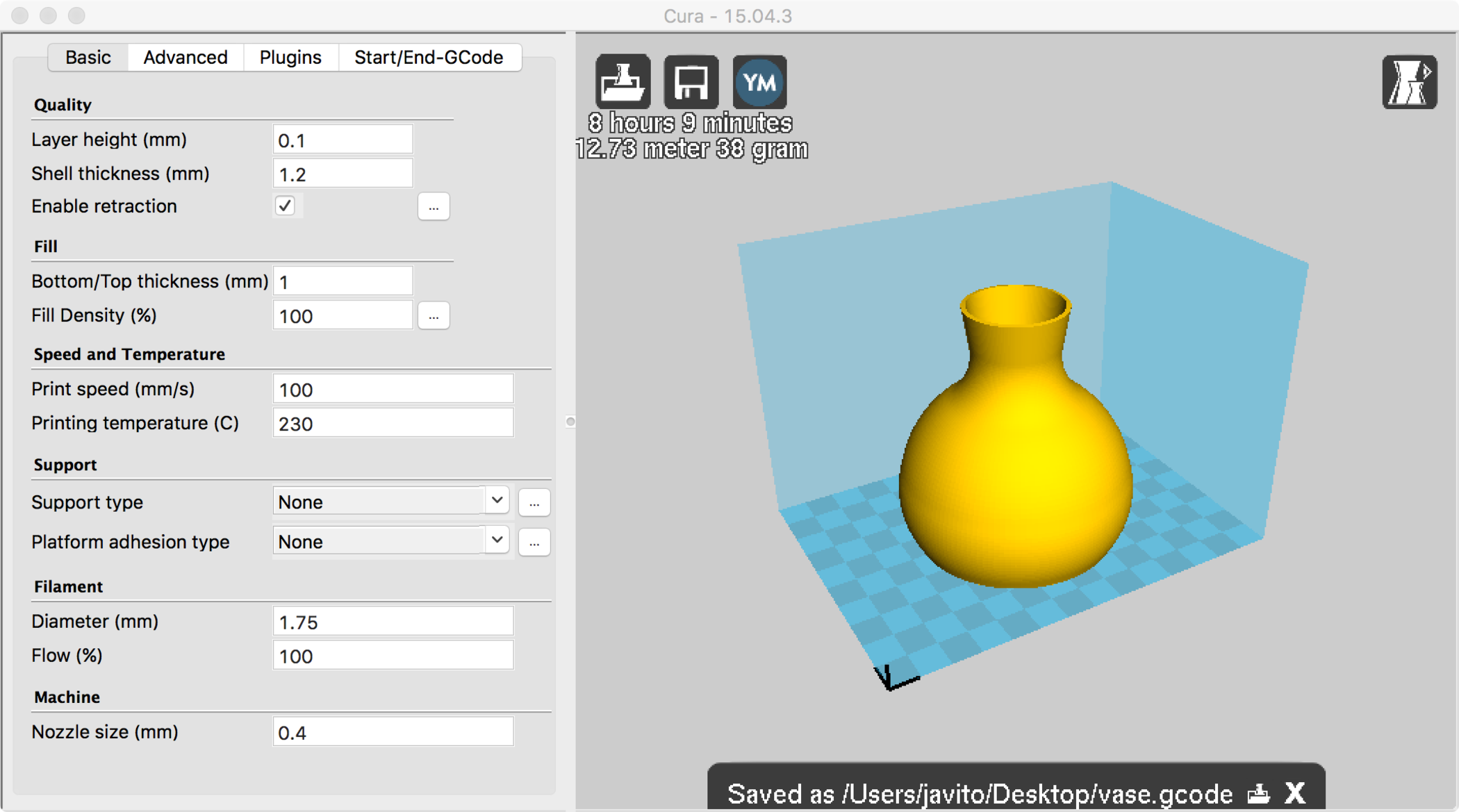
The other parameters are the official Sharebot Kiwi profile setings that can be found in their support page
3D Scanning
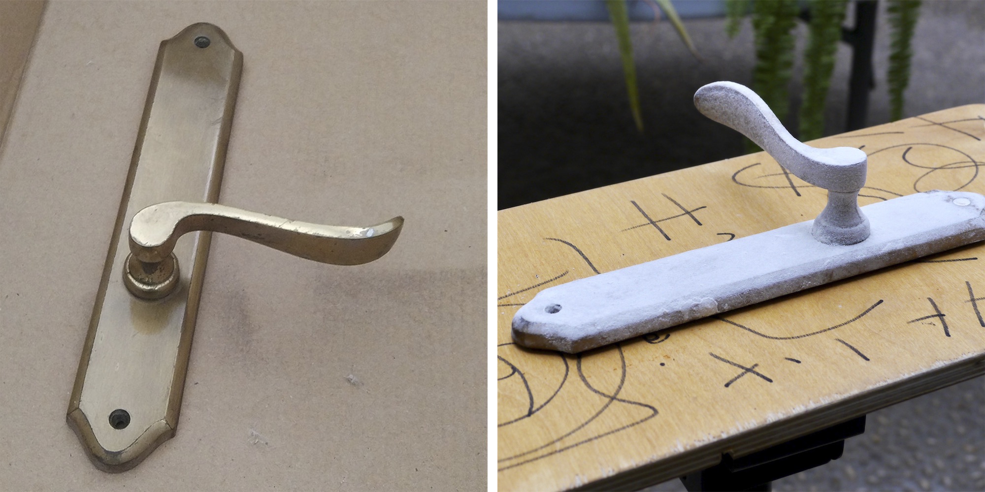
For the 3D scanning task I decided to try photogrammetry as it seems that it can be more effective when dealing with all the different architectural scales –from scanning small architectural features to entire spaces or buildings– The software of choice was Autodesk Remake and the object for scanning is an old door handle with clean but elaborate shape.
Photogrammetry does not work well on transparent, translucent or shiny objects so because my object is made of brass first thing I had to do is to cover up all the metallic reflections. It seems that there is some removable spray paint with matte finish but I couldn't source it locally so I used hairspray and dusted the object with flour.
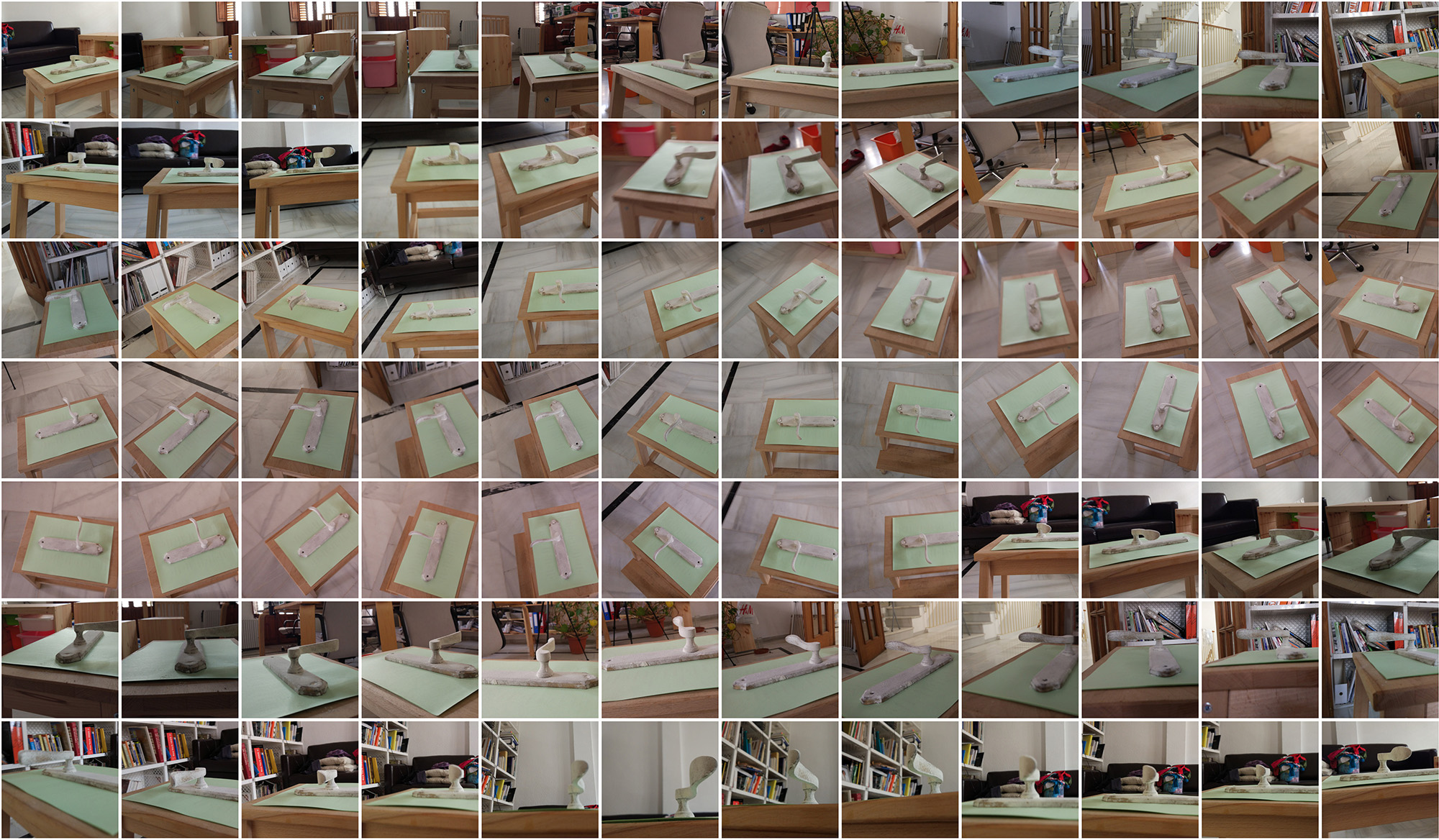
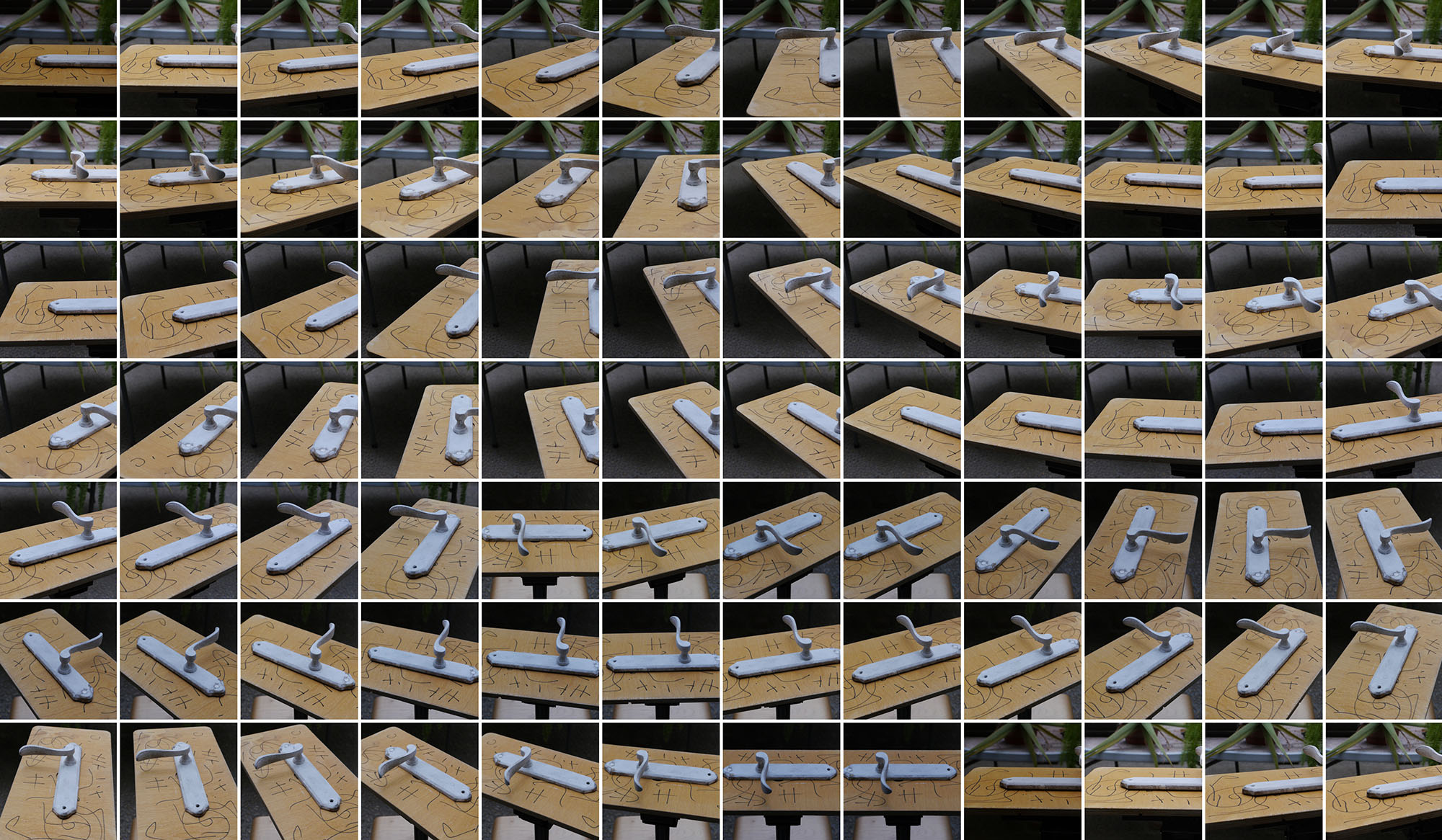
Then, I placed the door handle in a flat surface and with the cell phone camera orbited multiple with different inclinations, I tried to do it as consistent as possible but without using any tripod and/or rotating base. Room had a decent diffuse light with no hard shadows and consistent lighting. I uploaded all the folder into Autodesk Remake and waited about 30min for the images to upload and be processed in Autodesk servers. Results were quite disappointing, I realized that the photos should be taken much more carefully and consistently and lighting had to be much better.
I did further research on how to improve results. This video gives very useful tips on how to take the best photos for this process. Basically, avoid any reflections and refractions, make sure that there is enough overlap between images, use high f-stops so the whole object is on focus and use a tripod around the object in 15º degrees increments.
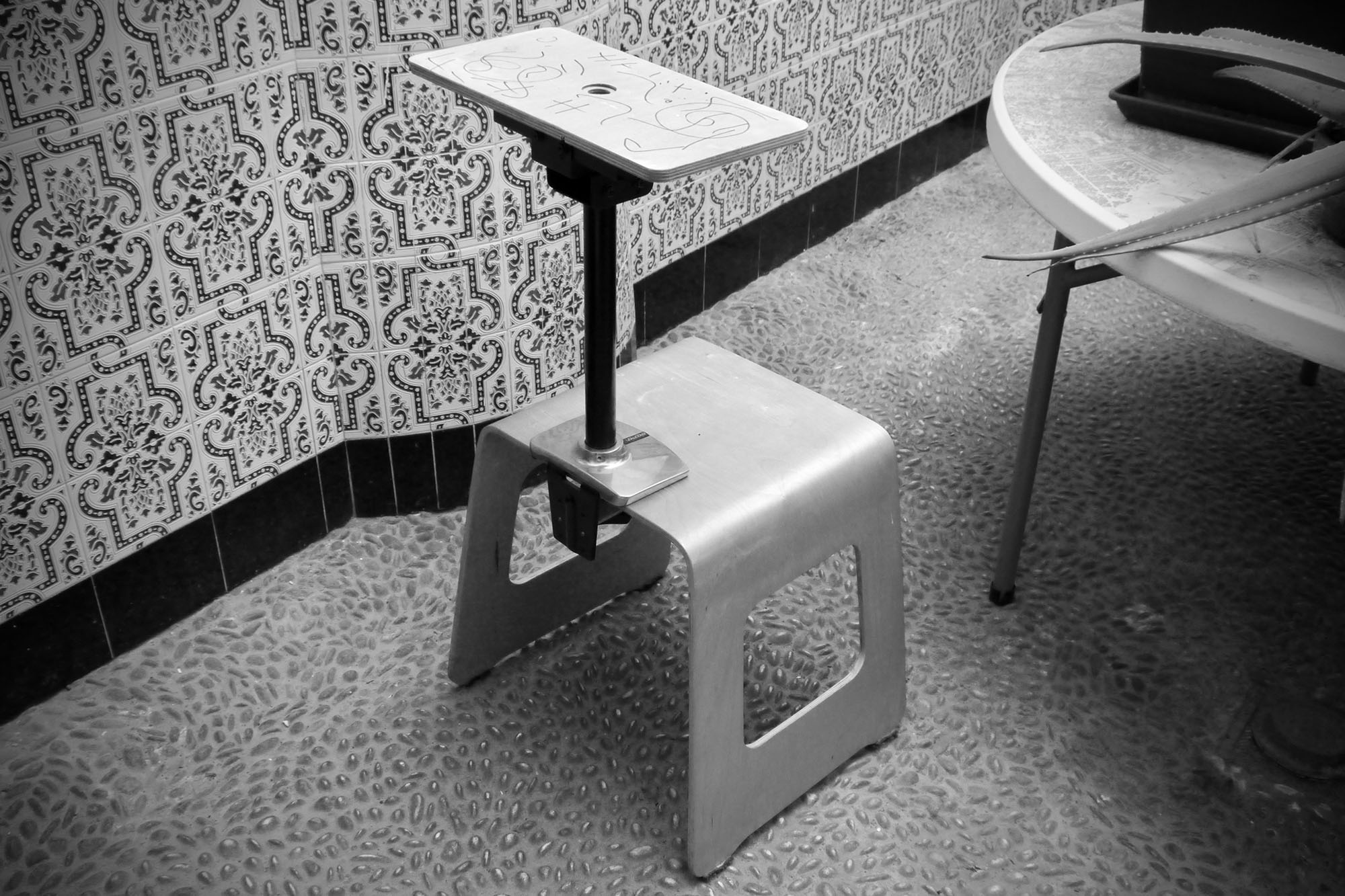
Next attempt I set up a better environment with a stationary tripod and my DSRL camera, a rotating base made with an Ikea stool and some parts from a screen arm holder and a projector ceiling mount.
Results were much better but I wasnt entirely happy with the results, after further researching I realized that using a different base pattern could improve the results. Below is the second test model.
Third attempt, I decided to improve the light quality, increase the number of photos and include some printed text on the base to increase the number of reference points
Results were really disappointing. Not sure what happened but the object was completely lost. Best results so far has been attempt number two. Timber base may have helped to differentiate the object from the base and background was out of focus so that might have helped as well. For next iteration I will try to improve both.
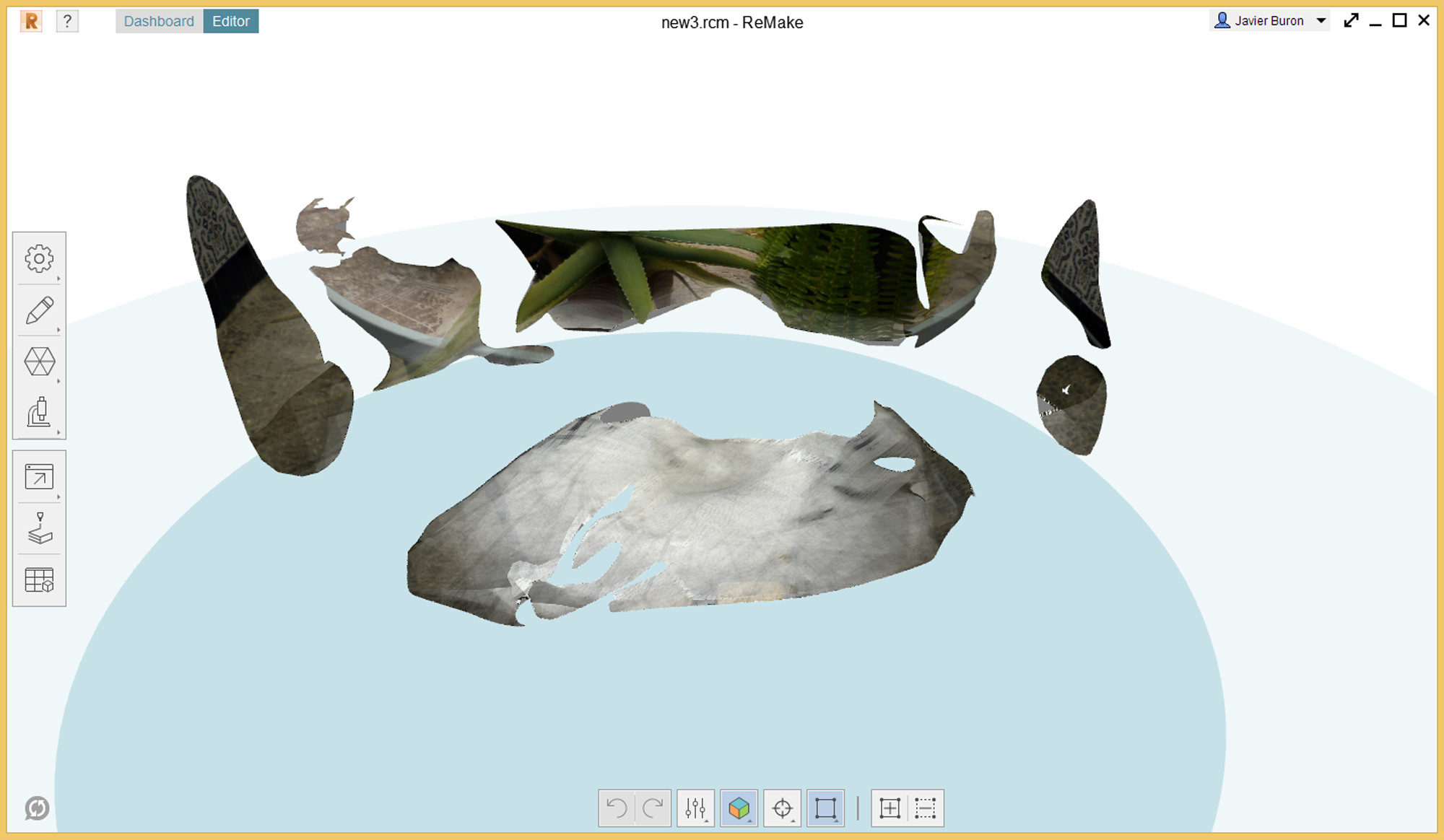
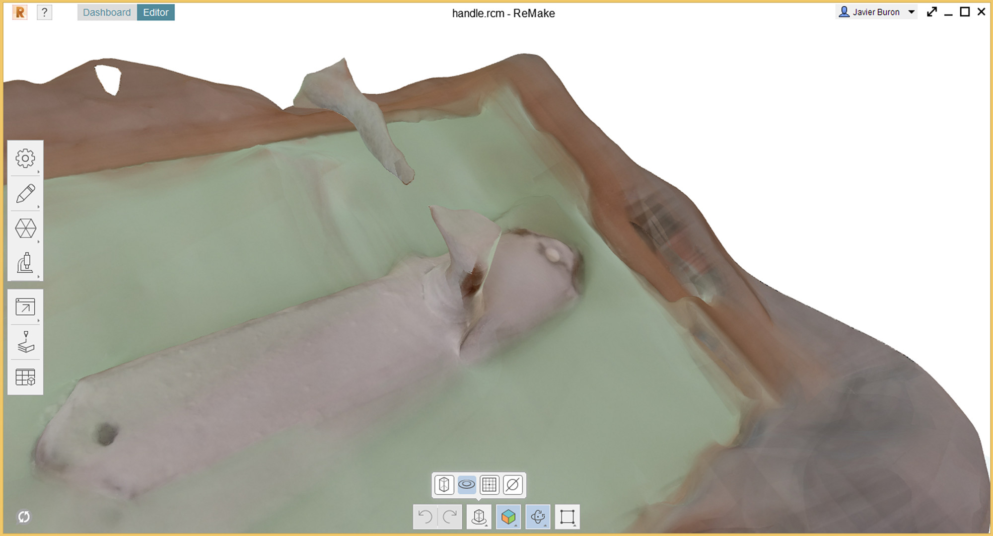
For my last iteration I used a dark textured base for the object and adjusted depth of field to blur the background and used a neutral background. The algorithmin worked perfectly this time, background was sucessfully removed and results were quite satisfactory. Autodesk remake has good tools for polygon editing so I spend some time removing the base and exported the model afterwards.
On the video above you can see the last shoot and below the 3D scanned model after clean up.