14 NETWORKINGS AND COMMUNICATIONS

Index
| HAVE YOU | TASK COMPLETED |
|---|---|
| Described your design and fabrication process using words/images/screenshots | YES |
| Explained the programming process/es you used | YES |
| Outlined problems and how you fixed them | YES |
| Included original design files and code | YES |
This Week the goal is learned about networking and communications making a network wired or not with 2 microprocessor at list. So I decided work on my final project practicing communications between boards trying to create a symbiotic system
After the class in order to understand how to make a network with my boards, i decided to learn about "Serial Communication" so i decided research a bit founding some useful to tutorials such as :
From there i made a sumary about the main concepts.
THE DIFFERENCE BETWEEN PARALEL AND SERIAL
In order for those individual circuits to swap their information, they must share a common communication protocol. Hundreds of communication protocols have been defined to achieve this data exchange, and, in general, each can be separated into one of two categories: parallel or serial.
Parallel interfaces transfer multiple bits at the same time. They usually require buses of data - transmitting across eight, sixteen, or more wires. Data is transferred in huge, crashing waves of 1’s and 0’s.
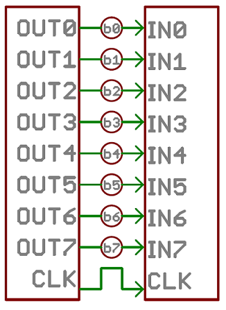
An 8-bit data bus, controlled by a clock, transmitting a byte every clock pulse. 9 wires are used.
Serial interfaces stream their data, one single bit at a time. These interfaces can operate on as little as one wire, usually never more than four.
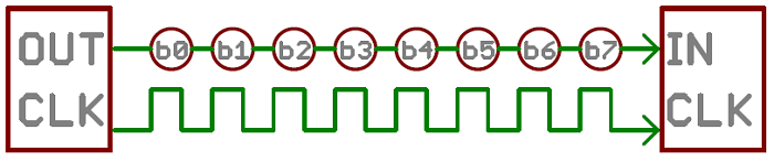
Think of the two interfaces as a stream of cars: a parallel interface would be the 8+ lane mega-highway, while a serial interface is more like a two-lane rural country road. Over a set amount of time, the mega-highway potentially gets more people to their destinations, but that rural two-laner serves its purpose and costs a fraction of the funds to build.
Parallel communication certainly has its benefits. It’s fast, straightforward, and relatively easy to implement. But it requires many more input/output (I/O) lines. If you’ve ever had to move a project from a basic Arduino Uno to a Mega, you know that the I/O lines on a microprocessor can be precious and few. So, we often opt for serial communication, sacrificing potential speed for pin real estate.
THE DIFFERENCE BETWEEN ASYNCHRONOUS or SYNCHRONOUS SERIAL
Each serial interfaces can be sorted into one of two groups: synchronous or asynchronous.
THE MECHANISM FOR ESCHEWING THE EXTERNAL CLOCK SIGNAL
THE INPORTANCE OF THE BAUDRATE
The baud rate specifies how fast data is sent over a serial line. It’s usually expressed in units of bits-per-second (bps). If you invert the baud rate, you can find out just how long it takes to transmit a single bit. This value determines how long the transmitter holds a serial line high/low or at what period the receiving device samples its line.
The only requirement is that both devices operate at the same rate. One of the more common baud rates, especially for simple stuff where speed isn’t critical, is 9600 bps.
UNDERSTANDING SYNCHRONIZITATION AND PARITY BITS
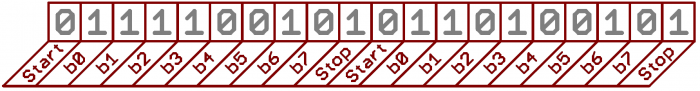
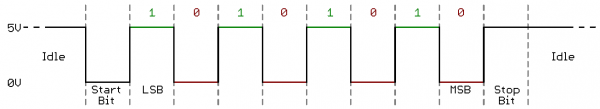
The synchronization bits are two or three special bits transferred with each chunk of data. They are the start bit and the stop bit(s) these marks the begining and end of a packet of data.
Parity is a form of very simple, low-level error checking. It comes in two flavors: odd or even. To produce the parity bit, all 5-9 bits of the data byte are added up, and the evenness of the sum decides whether the bit is set or not. For example, assuming parity is set to even and was being added to a data byte like 0b01011101, which has an odd number of 1’s (5), the parity bit would be set to 1. Conversely, if the parity mode was set to odd, the parity bit would be 0.
A device transmitting the ASCII characters ‘O’ and ‘K’ would have to create two packets of data. The ASCII value of O (that’s uppercase) is 79, which breaks down into an 8-bit binary value of 01001111, while K’s binary value is 01001011. All that’s left is appending sync bits. It isn’t specifically stated, but it’s assumed that data is transferred least-significant bit first. Notice how each of the two bytes is sent as it reads from right-to-left.
For every byte of data transmitted, there are actually 10 bits being sent: a start bit, 8 data bits, and a stop bit. So, at 9600 bps, we’re actually sending 9600 bits per second or 960 (9600/10) bytes per second.
HOW TO WIRE
A serial bus consists of just two wires - one for sending data and another for receiving. As such, serial devices should have two serial pins: the receiver, RX, and the transmitter, TX.
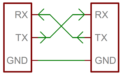
It’s important to note that those RX and TX labels are with respect to the device itself. So the RX from one device should go to the TX of the other, and vice-versa. It’s weird if you’re used to hooking up VCC to VCC, GND to GND, MOSI to MOSI, etc., but it makes sense if you think about it. The transmitter should be talking to the receiver, not to another transmitter.
When microcontrollers and other low-level ICs communicate serially they usually do so at a TTL (transistor-transistor logic) level. TTL serial signals exist between a microcontroller’s voltage supply range - usually 0V to 3.3V or 5V. A signal at the VCC level (3.3V, 5V, etc.) indicates either an idle line, a bit of value 1, or a stop bit. A 0V (GND) signal represents either a start bit or a data bit of value 0.
TTL is much easier to implement into embedded circuits. However the low voltage levels are more susceptible to losses across long transmission lines.
HOW TO CONVERT DATA ON A PARALLEL BUS TO/AND FROM SERIAL INTERFACE
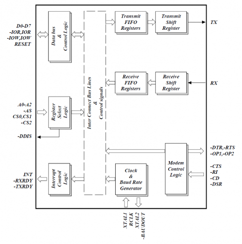
UART, create the serial packets and control those physical hardware lines. A universal asynchronous receiver/transmitter (UART) is a block of circuitry responsible for implementing serial communication. Essentially, the UART acts as an intermediary between parallel and serial interfaces. On one end of the UART is a bus of eight-or-so data lines (plus some control pins), on the other is the two serial wires - RX and TX.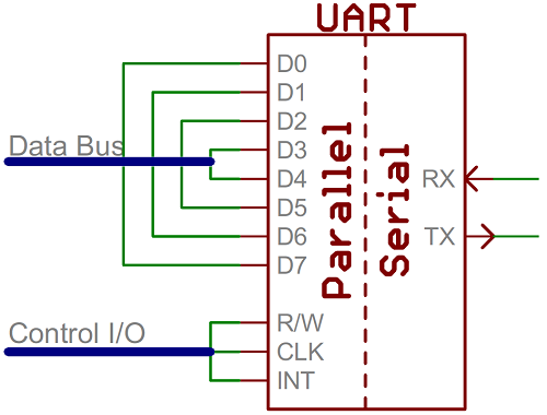
As the R and T in the acronym dictate, UARTs are responsible for both sending and receiving serial data. On the transmit side, a UART must create the data packet - appending sync and parity bits - and send that packet out the TX line with precise timing (according to the set baud rate). On the receive end, the UART has to sample the RX line at rates according to the expected baud rate, pick out the sync bits, and spit out the data.
If a microcontroller doesn’t have a UART (or doesn’t have enough), the serial interface can be bit-banged - directly controlled by the processor. This is the approach Arduino libraries like SoftwareSerial take.
BUS CONTENTION
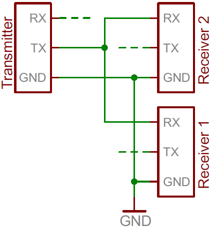
Serial communication is designed to allow just two devices to communicate across one serial bus. If more than one device is trying to transmit on the same serial line you could run into bus-contention.
Two devices trying to transmit data at the same time, on the same line, is bad! but it can be safe to connect multiple receiving devices to a single transmitting device.
For example, My board’s TX is already connected to the USB programmer’s RX line and i want to connect my CO2 sensor board to the board i will connect his RX to my TX board.
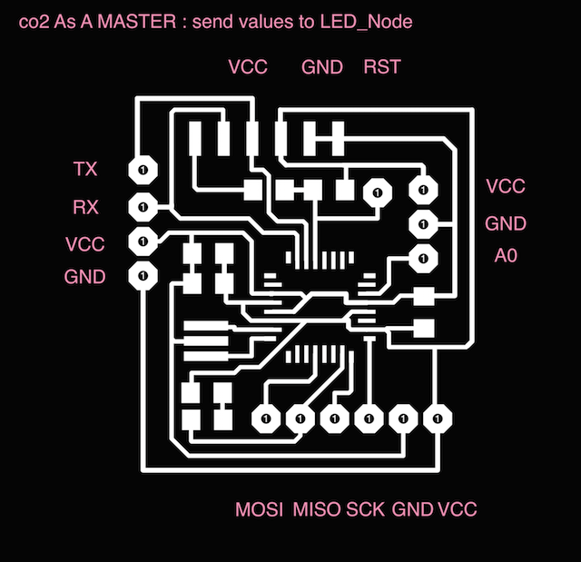
THE MASTER : Send values to the Slave or Slaves
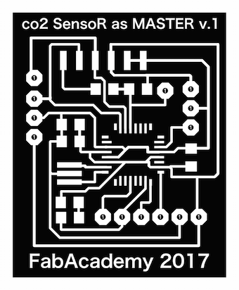
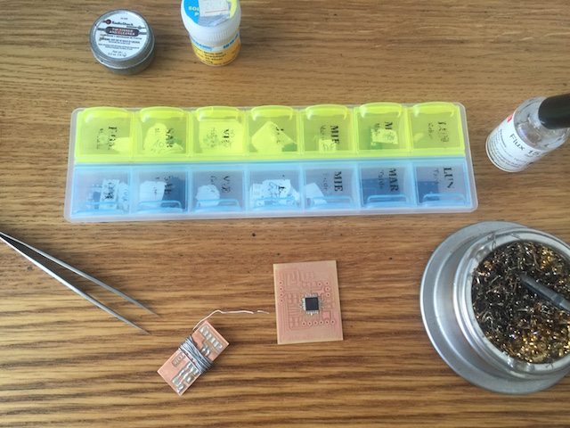
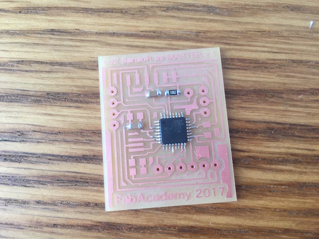
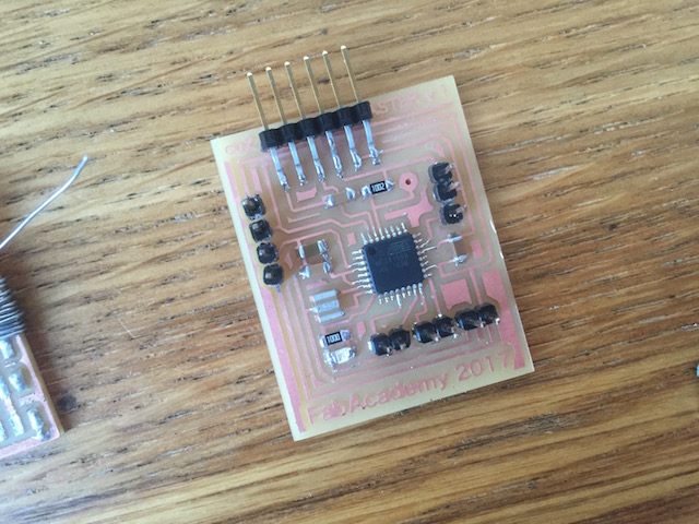
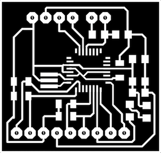
1. In order to advance with my final project, i designed the Input Board (Co2 Sensor based in FabKit v.04)
for use as a MASTER for send values to the LED_NODE 2, first. The process was easy because just had to add the pad for make more TX and RX connections and changed the Led to MOSI for have indications when connections be success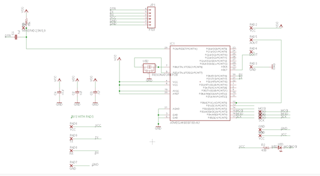
2. As want to have some Powers, i conserved the FTDI connections for program the boards with my computer.
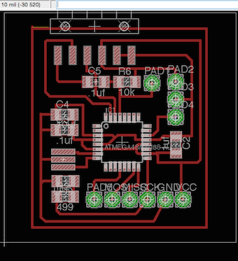
3. When i finished, exported my BOM list for buy the components later.
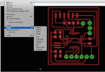
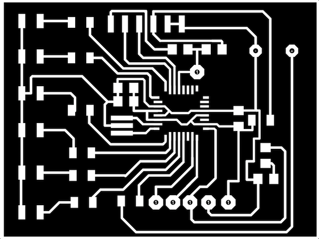
4. An export Image as .png with 1500 dpi resolution and Monochrome.

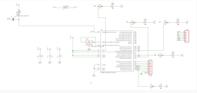
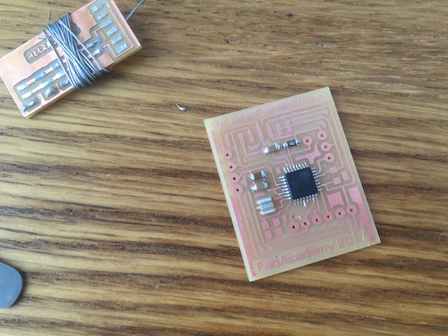
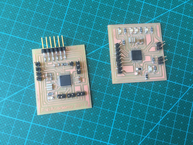
THE SLAVE : My idea is to receive Values from the Master acording to a range maped previously.
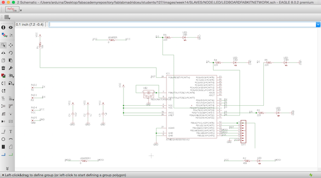
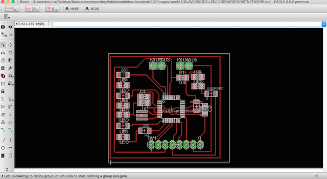
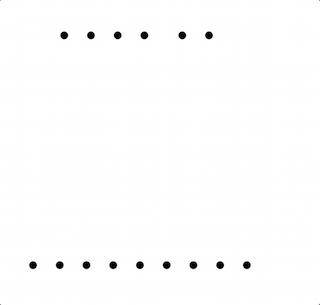
I made a design based in the board fabricated at the Output Devices Assigment Week
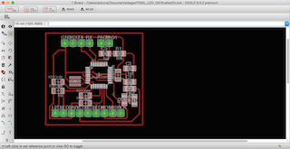
OUTPUT Design
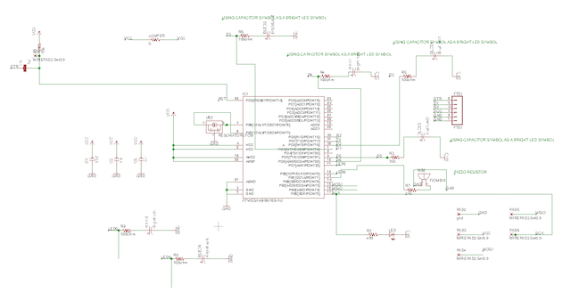
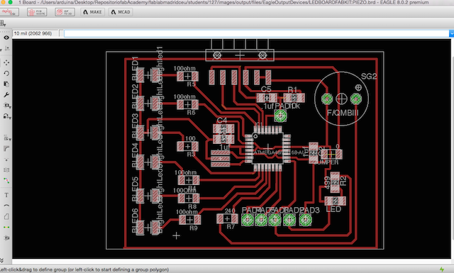
So here are my Eagle Project with different leds but using the same micro-processor with the idea to continue with the datasheet study.
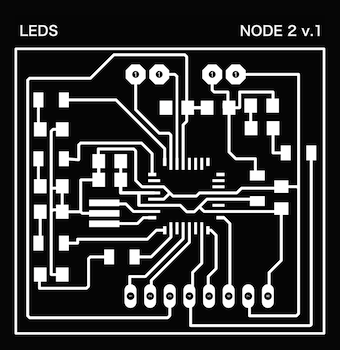


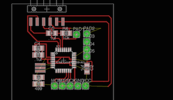
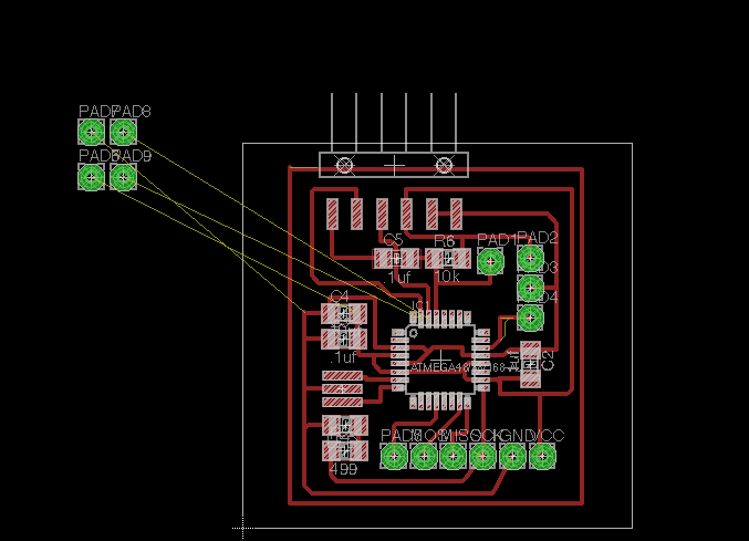
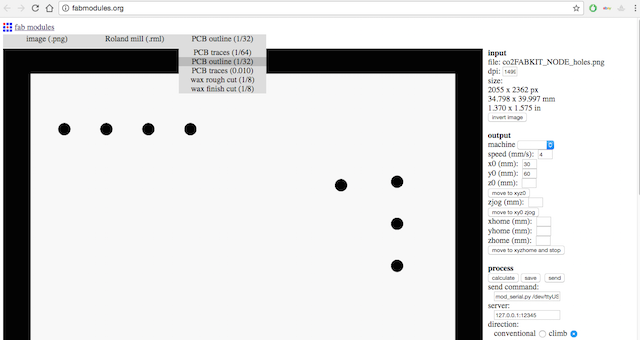
1. Imported my Interior File for mill with 1/64 mill at fabmodules :

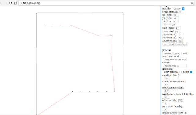
2. Calculating for check things and take a preview about how the mills work :

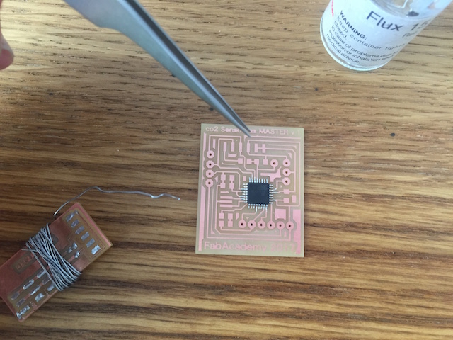
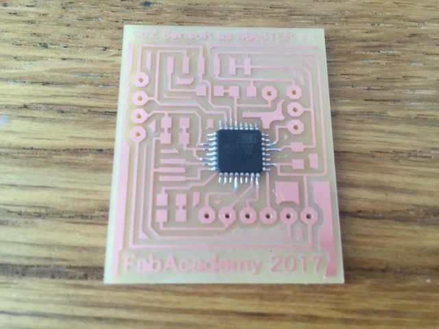
3. Mill Results:

4. Later i repeated the same operation but changing the mill by a 1/32 one.

5. Imported my holes file and cuted the board :

6. For finish, i improted the Outlines File with the same mill :

7. For each board i repeated the same process, after this i have new board for communicate between both.
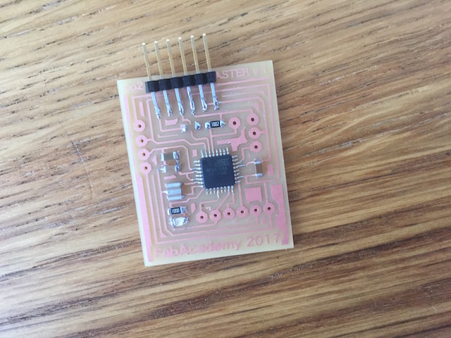
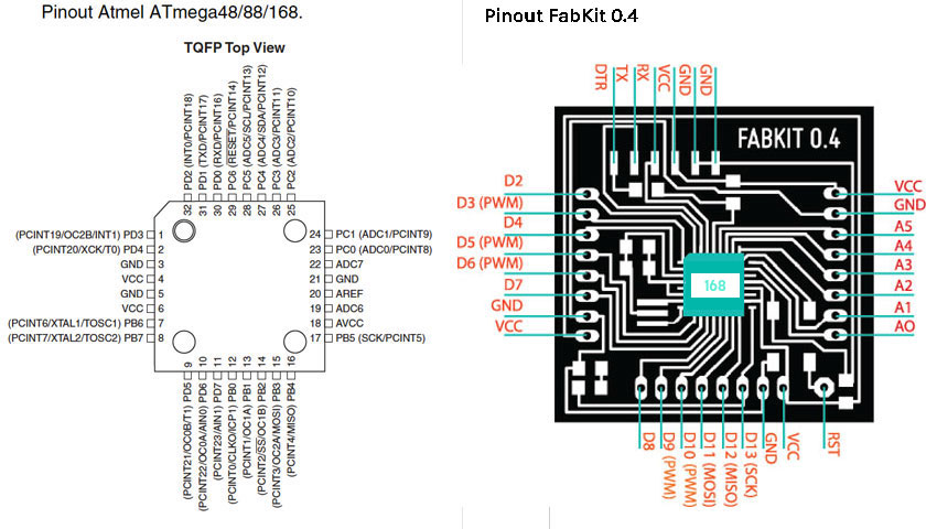
The connections follow the pic showed above :
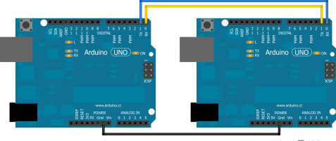
As you can see at Arduino References, i have to connect TX with RX and RX with TX : The "master" should write over Serial the desired value and the "slave" will be reads it and something happens!. This is the first idea...
I had to remember the AtMega 168 pinout correspondance with Arduino to identify the RX/TX pins. RX must be connected with TX in the other board and TX to RX as well.
Here began my problems described at WEEK PROBLEMS SECTION and HOW I SOLVED.
Our instructor always correct our designs before mill so he know our future problems later and when went with him for explain my problems, he learned to about how my mistake miss all the micro-processor logic because i forgot the DTR trace and now is not connect to nothing so he suggested to me focuss in my final project and design a board which i shuold use later.
1ST ATTEMPT
For practice the first concept about serial communications, i decided to follow the arduino reference at their Official Website and was researching in other students assignments for have new conclusions and understand better the things to do.
After i had clear my RX and TX pin at my boards i decided to connect boths following the correspondance learned from datasheet read :
For serial communication, i need the SoftwareSerial Library installed at my Arduino IDE, so here are the references followed :
The Arduino hardware has built-in support for serial communication on pins 0 and 1 (which also goes to the computer via the USB connection). The native serial support happens via a piece of hardware (built into the chip) called a UART. This hardware allows the Atmega chip to receive serial communication even while working on other tasks, as long as there room in the 64 byte serial buffer.
The SoftwareSerial library has been developed to allow serial communication on other digital pins of the Arduino, using software to replicate the functionality (hence the name "SoftwareSerial"). It is possible to have multiple software serial ports with speeds up to 115200 bps. A parameter enables inverted signaling for devices which require that protocol.
The version of SoftwareSerial included in 1.0 and later is based on the NewSoftSerial library by Mikal Hart.
The SoftwareSerial Library has been developed to allow serial communication to take place on the other digital pins of your boards, using software to replicate the functionality of the hardwired RX and TX lines. This can be extremely helpful when the need arises to communicate with two serial enabled devices, or to talk with just one device while leaving the main serial port open for debugging purpose.
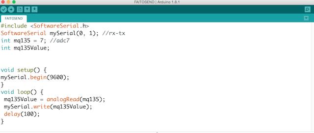
My Co2 Sensor Board was giving me a short noisy range of values. Then, for test if the Serial Communication is working properly, I hand-shacked the values to send over serial between the two boards.
In the example at his refrence web page, digital pins 10 and 11 on your Arduino or Genuino boards are used as virtual RX and TX serial lines. The virtual RX pin is set up to listen for anything coming in on via the main serial line, and to then echo that data out the virtual TX line. Conversely, anything received on the virtual RX is sent out over the hardware TX.
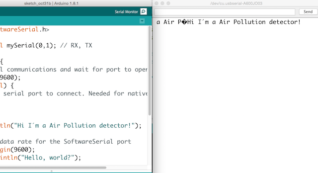
My boards are using 0 and 1 for RX and TX so i modiffied the example for have appropiate pins to this numbers, the other thing i made was change the baudrate to 9600 and add a custom message for know that my sensor is living.
First i made a test for blink the mosi led
Networking: Master Test I from Pilu Caballero on Vimeo.
2. I modiffied the Software serial example for practice the monitor serial communication :
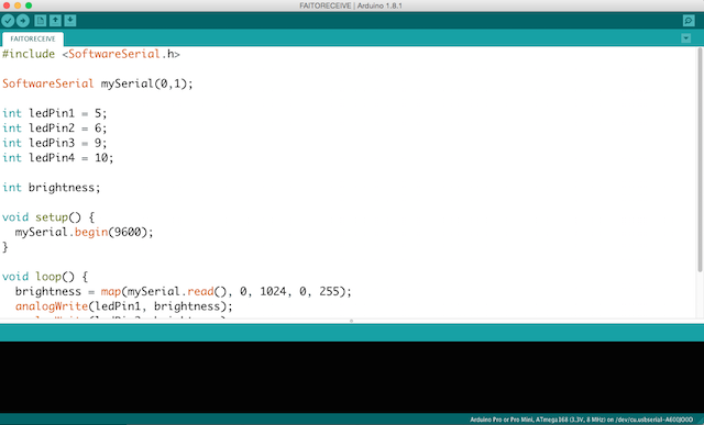
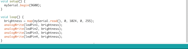
/* Software serial multiple serial test Receives from the hardware serial, sends to software serial. Receives from software serial, sends to hardware serial. The circuit: * RX is digital pin 0 (connect to TX of other device) * TX is digital pin 1 (connect to RX of other device) created back in the mists of time modified 25 May 2012 by Tom Igoe based on Mikal Hart's example This example code is in the public domain. */ #includeSoftwareSerial mySerial(0,1); // RX, TX void setup() { // Open serial communications and wait for port to open: Serial.begin(9600); while (!Serial) { ; // wait for serial port to connect. Needed for native USB port only } Serial.println("Hi I´m a Air Pollution detector!"); // set the data rate for the SoftwareSerial port mySerial.begin(9600); mySerial.println("Hello, world?"); } void loop() { // run over and over if (mySerial.available()) { Serial.write(mySerial.read()); } if (Serial.available()) { mySerial.write(Serial.read()); } }
2nd ATTEMPT
Here are some references programs which o adapted for use with my boards.
void setup() {
  // initialize
  Serial.begin(9600);
}

void loop() {
  Serial.print('0');
  delay(100);
  Serial.print('1');
  delay(100);

}
// Arduino read data from serial from another Arduino

const int ledPin =  11;      // the number of the LED pin where i attached my led MOSI

char data;

void setup() {
  // initialize
  pinMode(ledPin, OUTPUT);
  Serial.begin(9600);
}

void loop() {
  data = Serial.read();

  if (data == '1') {
    digitalWrite(ledPin, HIGH);
    // Debug if the data check works
    Serial.print("ok");
} else {
 digitalWrite(ledPin, LOW);
  }
  delay(100);
}
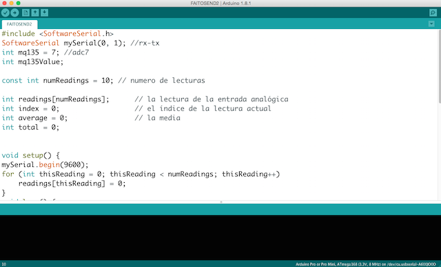
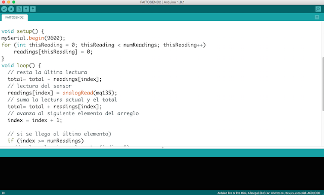
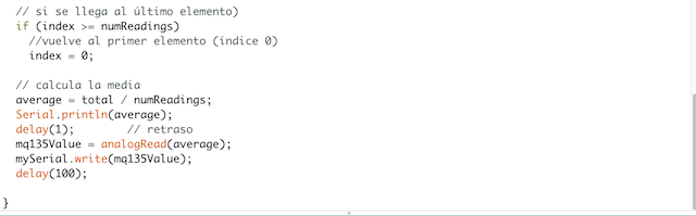
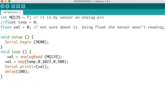
I wrote this program for test the Master Board with the sensor with the idea to approximate to the final idea
float MQ 135 = 7;
int gas = 0;
int valgas = 0;
int LED = 11;
void setup () {
  Serial.begin (9600);
  pinMode (LED, OUTPUT);
  //digitalWrite (LED, 0);
}

void loop () {
  // We read the gas data, and behave accordingly
  valgas = analogRead(MQ 135);
  Serial.println(valgas);

  if (valgas <= 200){
      digitalWrite (LED, LOW);
      delay (1000);
    }
    else if (valgas > 200) {

     digitalWrite (LED, HIGH);
     delay (1000);
   }
}
void valgas () {
  gas = analogRead (MQ 135);
  Serial.println (PollutionRisk);
}
Networking: Master Test I from Pilu Caballero on Vimeo.
The idea is use my computer as a Master, so i must to connect my boards in serie so TX from my Input board must to be connected to the TX from my Output Board. The first Slave will be coonnect to the computer trought RX.
So here is the program for the first Slave :
int led = 11;

char activar = 0;
char name = '1';
int Tx = 1;

void setup () {

pinMode (led, OUTPUT);
Serial.begin (9600);

}

void loop () {

digitalWrite (Tx, LOW); // Tx in tristate
pinMode (Tx, OUTPUT);

 if (Serial.available ()) {
    activar = Serial.read ();
    Serial.println (activar);

  if (activar == name) {
  pinMode (Tx, OUTPUT);
  digitalWrite (led,HIGH);
  Serial.print ("nodo 1");
  delay (1000);
  digitalWrite (led,LOW);
    }
   else {
   digitalWrite (Tx, LOW);
   }
    }
     }
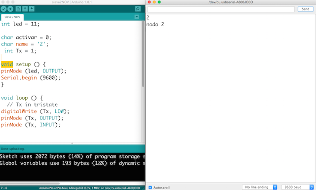
int led = 11;

char activar = 0;
char name = '2';
int Tx = 1;

void setup () {
pinMode (led, OUTPUT);
Serial.begin (9600);
}

void loop () {
  // Tx in tristate
digitalWrite (Tx, LOW);
pinMode (Tx, OUTPUT);
pinMode (Tx, INPUT);


 if (Serial.available ()) {
 activar = Serial.read ();
    Serial.println (activar);
    if (activar == name) {
    pinMode (Tx, OUTPUT);
    digitalWrite (led,HIGH);
    Serial.println ("nodo 2");
    delay (1000);

  digitalWrite (led,LOW);
    }
    else{digitalWrite (Tx, LOW);}
}
 }
For finnish i connected both boards : RX to RX and TX to TX and GND to GND and VCC to VCC and the NODE 1 (The CO2 board ) to the computer trying to send message from monitor and see how them is ocmmunicates :
I have a problem designing my slave board, i forgot the DTR pin so as my instructor learned to me, i miss all the logic of the board so she suggested me, focuss in my final project and design a possible final board. So the rest of teh assignment i finished with this board.
This weeks i have some problems to understand correctly the task to do. why? the Neil example is really clear and i wont to fabricate the boards suggested but my instructor suggested me focuss in my final project and use another board fabricated in previous assignment so this cause me some confussions but thanks to Cova and her simple explanations finally i made my programs.
As i never made something similar, all the assignment learned me a lot and now i can connect more than 3 processors using my terminal as a master.
WEEK FILES
MY FINAL PROJECT
Thinking in my final Project i begin with the CO2 Sensor Callibration explained in my
Final Project Process Page at Programming processes section.
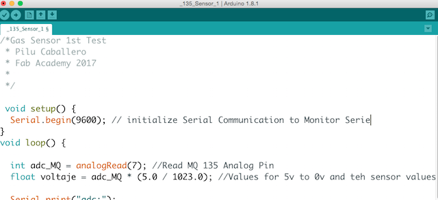
MY SENSOR:


References about Gas Sensors
I found at the Arduino Offical Web page some refrences about the use of this kind of sensors, there you can find basic overwiew with data sheets about the family but i decided copied to this page for never forget the basics things :
Introduction
The MQ series of gas sensors use a small heater inside with an electro-chemical sensor. They are sensitive for a range of gasses and are used indoors at room temperature.
They can be calibrated more or less (see the section about "Load-resistor" and "Burn-in") but a know concentration of the measured gas or gasses is needed for that.
The output is an analog signal and can be read with an analog input of the board i designed.
Read the datasheet
Try to find a few datasheets for the sensor, and read them careful.
Since there are no electronic components inside, therefor most sensors can be used with AC and DC voltages.
Be careful when connecting it for the first time. If the pins are connected wrong, the sensor could get damaged, or it could be broken instantly. There are also shields available with these sensors pre-installed.
Wiring
The preferred wiring is to connect both 'A' pins together and both 'B' pins together. It is safer and it is assumed that is has more reliable output results. Although many schematics and datasheets show otherwise, you are advised to connect both 'A' pins together and connect both 'B' pins together.

In the picture, the heater is for +5V and is connected to both 'A' pins. This is only possible if the heater needs a fixed +5V voltage.
The variable resistor in the picture is the load-resistor and it can be used to determine a good value. A fixed resistor for the load-resistor is used in most cases.
The Vout is connected to an analog input of the Board designed
The voltage for the internal heater is very important.
Some sensors use 5V for the heater, others need 2V. The 2V can be created with a PWM signal, using analogWrite() and a transistor or logic-level mosfet.
The heater may not be connected directly to an output-pin of the Arduino, since it uses too much current for that.
Some sensors need a few steps for the heater. This can be programmed with an analogWrite() function and delays. A transistor or logic-level mosfet should also in this situation be used for the heater.
If it is used in a battery operated device, a transistor or logic-level mosfet could also be used to switch the heater on and off.
The sensors that use 5V or 6V for the internal heater do get warm. They can easily get 50 or 60 degrees Celcius.
After the "burn-in time", the heater needs to be on for about 3 minutes (tested with MQ-2) before the readings become stable.
The sensor needs a load-resistor at the output to ground. It's value could be from 2kOhm to 47kOhm. The lower the value, the less sensitive. The higher the value, the less accurate for higher concentrations of gas.
If only one specific gas is measured, the load-resistor can be calibrated by applying a know concentration of that gas. If the sensor is used to measure any gas (like in a air quality detector) the load-resistor could be set for a value of about 1V output with clean air.
Choosing a good value for the load-resistor is only valid after the burn-in time.
Some datasheets use the term "preheat", but it is the time to burn-in the sensor. This is meant to make the sensor readings more consistent. A time of 12 or 24 hours is usually used for the burn-in time.
The Burn-in is achieved by applying normal power to the sensor (to the heater and with the 'A' and 'B' pins connected, and with a load-resistor). In some special cases a specific burn-in is needed. See the datasheet if the sensor needs such a specific burn-in.
Interesting links
MQ135 : A Sensor For Air Quality
- The heater uses 5V.
An example how to use it:
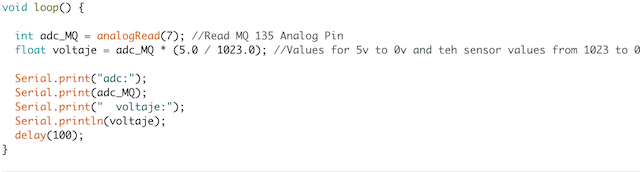
An example with calculation of the CO2 value:
Search for datasheet:
Networking: Master Test I from Pilu Caballero on Vimeo.
Faito v. 01 : High Bright Led Board from Pilu Caballero on Vimeo.
1TESTVOLTAGE_SERIAL from Pilu Caballero on Vimeo.
PROGRAMING INPUT DEVICES : TEST MQ135 WITH LITHIUM ION POWER SUPPLY from Pilu Caballero on Vimeo.
The processes for callibrated the sensors was a fight but finally i can detect some differents atmospherics gases. You can know more about this process in my Final Project Process Page :
OUTPUT DEVICES Receives information data from INPUT DEVICE blinking bright Leds described at Electronics section with mapped values from the analog sensor.
High Bright Leds from Pilu Caballero on Vimeo.
Testing Slave Board with a Bright Led from Pilu Caballero on Vimeo.
All the Files about this programs are at my :