Assignments:
- Redraw the echo hello-world board,
- Add (at least) a button and LED (with current-limiting resistor)
- Check the design rules, and make it
- Test it
- Extra credit: simulate its operation
- Extra credit: measure its operation
--- Doing the Sparkfun tutorials ---
I am going to do first the tutorial of sparkfun on the schematic design and the design of the board.
After Redraw the echo hello-world board.
You can see the tutorial here:
-Sparkfun schematic design tutorial
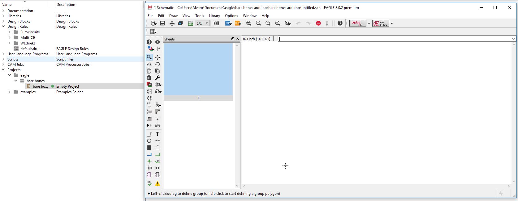 Opening a new project.
 configuring the design rules.
 Joining in groups to move more easily.
 adding atmega and components of the microcontroller.
 Making the joints.
 The final scheme.
You can see the tutorial here:
-Sparkfun board tutorial
 Placing the components.
 making the joins.
 Drawing the board.
--- Making the echo hello-world board ---
--- Steps for Redraw the echo hello-world board ---
1. Install the eagle circuit design program, and introduce the component libraries.
 I will use eagle for circuit design.
Eagle is an intuitive autodesk program to make electronic circuits and use component libraries, once designed you can export those designs in different formats, get lists of components ... etc.
I will use eagle for circuit design.
Eagle is an intuitive autodesk program to make electronic circuits and use component libraries, once designed you can export those designs in different formats, get lists of components ... etc.
Libraries are groups of blocks with the drawing of the component, name, number of pads, approximate size, etc.
When you want to design a plate and you do not have the component or design it yourself, or download it from the internet and place it in the corresponding Eagle folder.
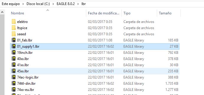 introducing the component libraries.
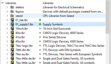 Placing the component libraries.
2. Open a new project and configure the design rules
Placing the component libraries.
2. Open a new project and configure the design rules
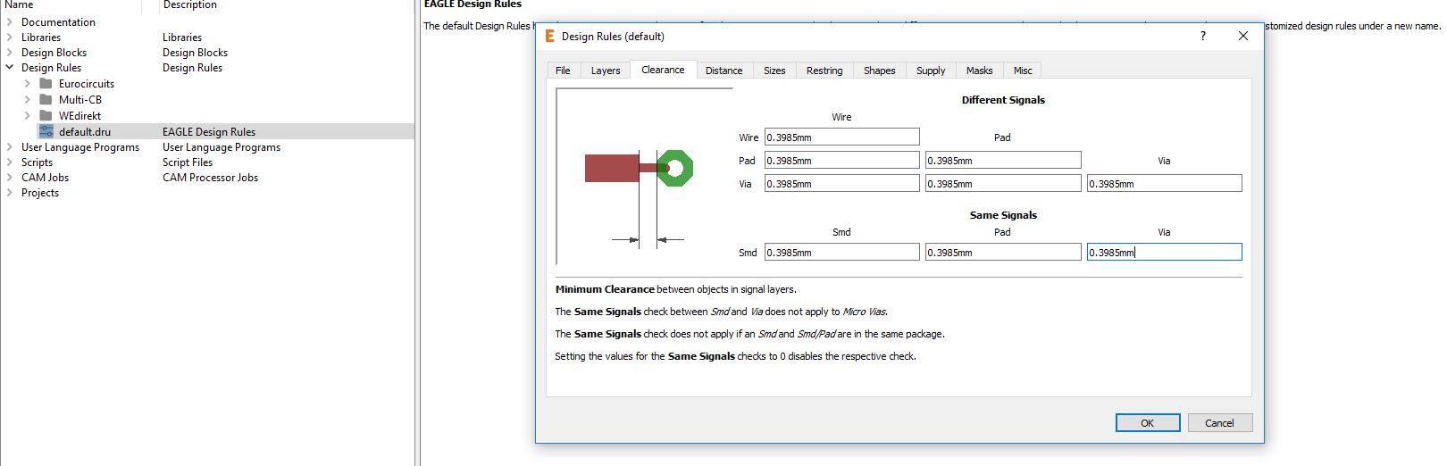
Design rules defines minimum and maximum sizes of wire, pads, distance between wires, and have to be depending on the machine and milling cutter you are using.
In this case for example I used the 0.3985 mm of clearence in the design rules for the next reason:
the diameter of the milling cutter to make the circuit is that, so clearance must be left at least,for the milling cutter can pass between wires.
 configuring the design rules.
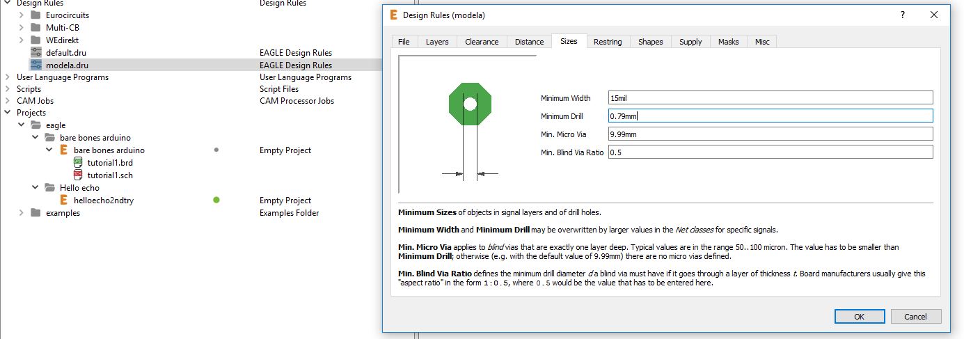 Changing the design rules.
3. Draw the schematic diagram of the circuit, adding all the components from the library
Changing the design rules.
3. Draw the schematic diagram of the circuit, adding all the components from the library
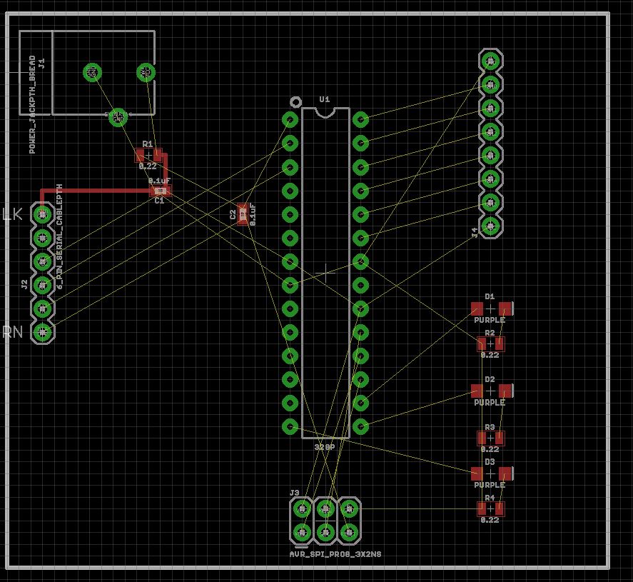
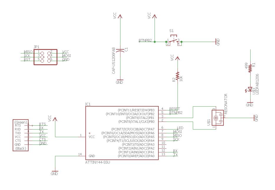
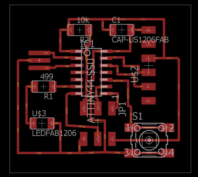
In the schematic drawing design you choose the components you are going to use and where your inputs and outputs are going to be connected.
It is used to get an idea that it is correctly connected and for the board design there are auxiliary lines of connection in the circuit.
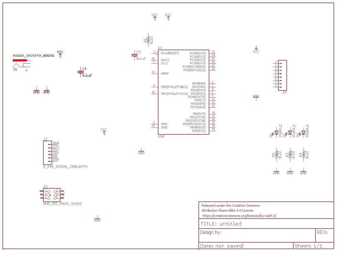
 This is what needs to be done.
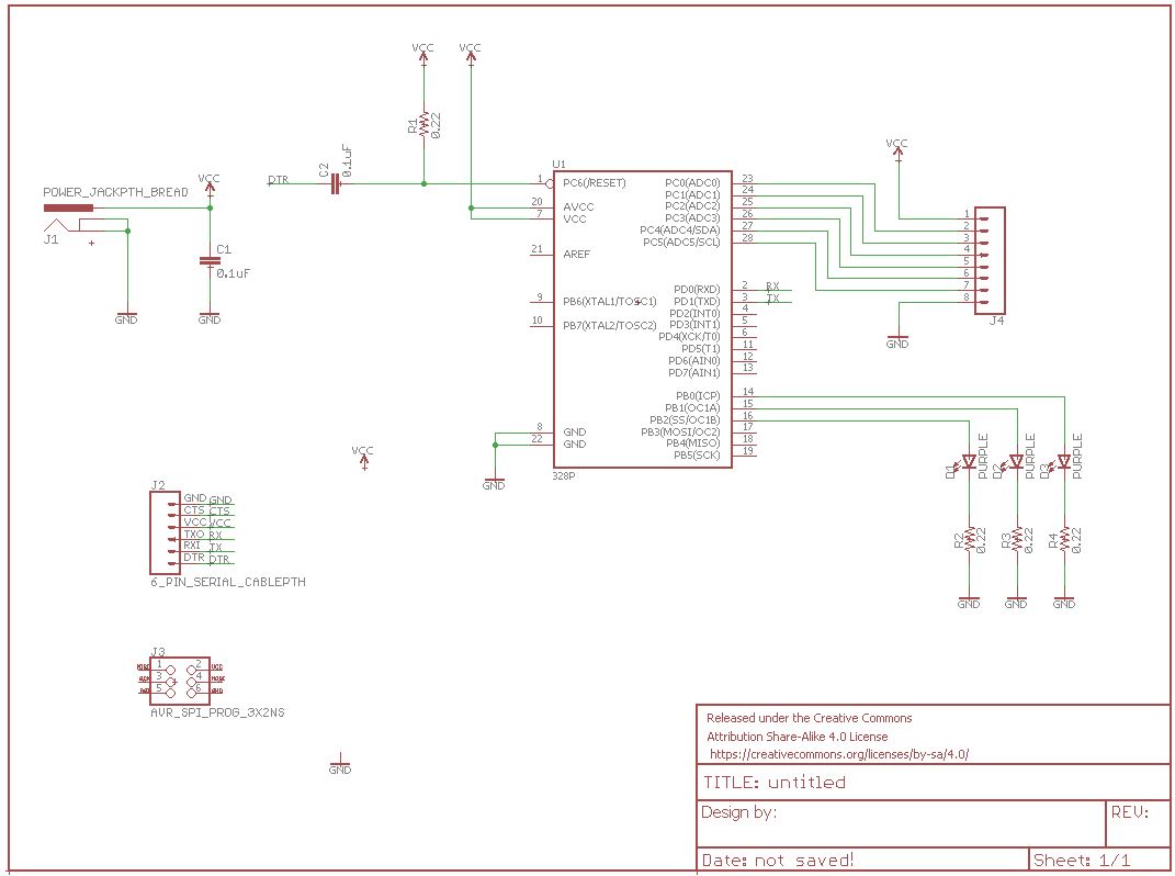
First I choose the components of the library and then I join the components together and with GND and VCC.
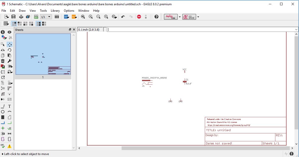
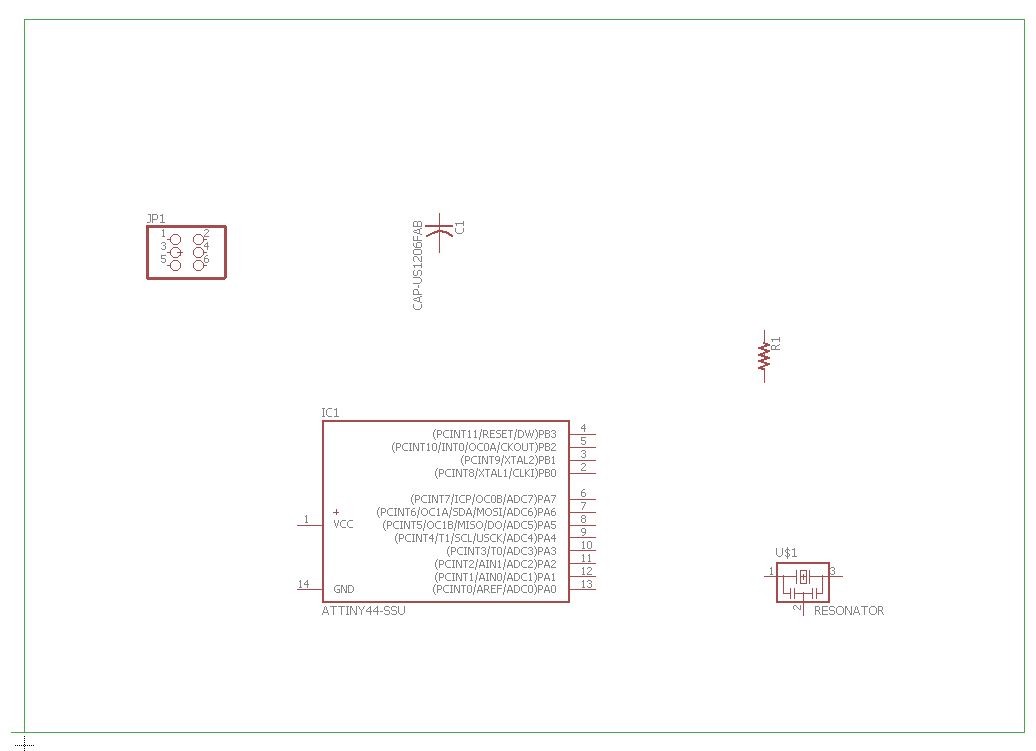 Adding my components.
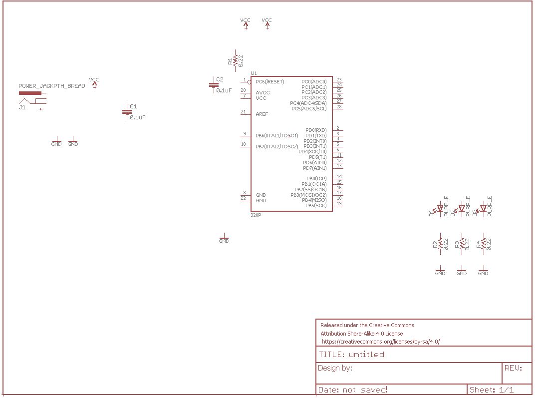
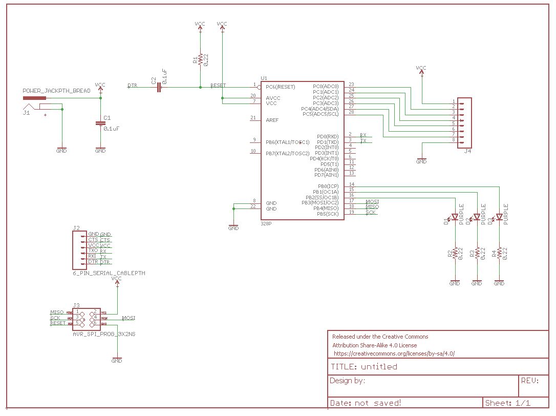
 Ending the schematic
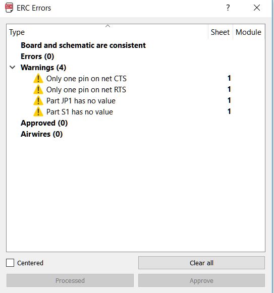 Warnings in the schematic
In my design warnings are shown that values are missing in the components
and named elements that do not connect, but are not errors and do not need to modify them.
Warnings in the schematic
In my design warnings are shown that values are missing in the components
and named elements that do not connect, but are not errors and do not need to modify them.5. Go to the design of the board.
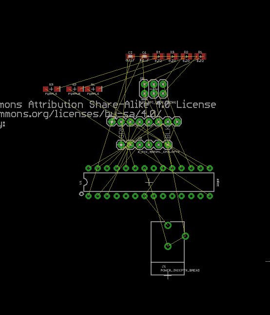
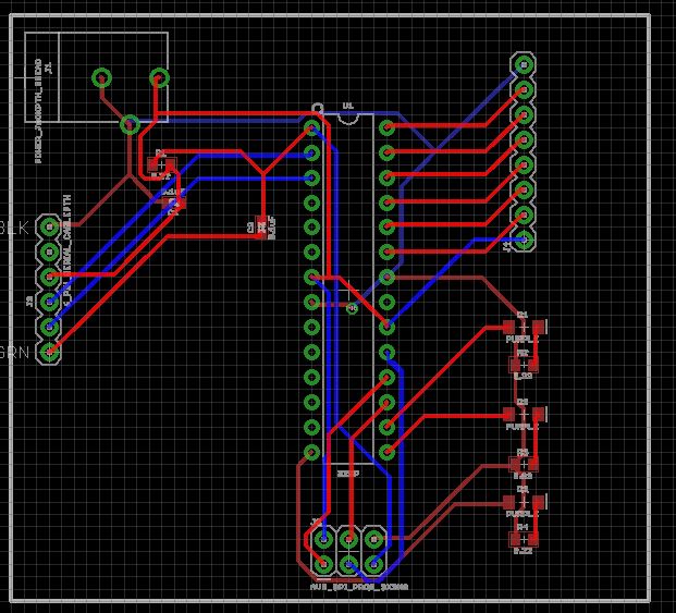
In this section we can design the board ready to fabricate, I put the components where I want leaving space to draw the wire.
 switching to board drawing mode.
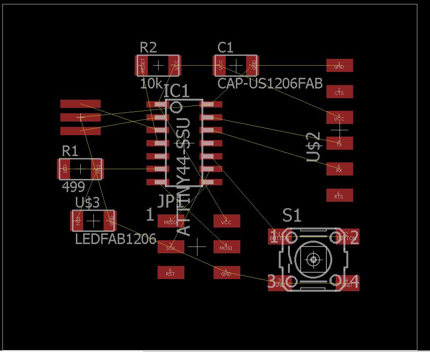 board drawing mode interface.
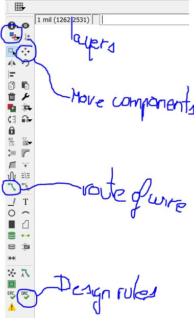 Tools.
Following the design rules I will also modify the type of traces that I will draw. So that the wire of the board has the right size I have to select with the drawing tool the wire width I want.
 width wire used.
recommended wire width to be 0.30 when approaching microcontroller pins 6. Draw all the wire and check that they are join, checking that the design rules are ok.
 Drawing my board.
in the layer tool we choose only the top layer to show us only the image with what we want to cut.
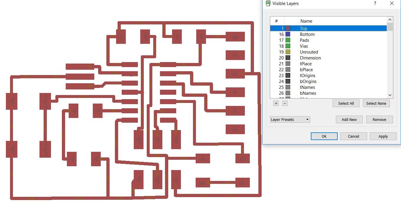 Selecting top layer.
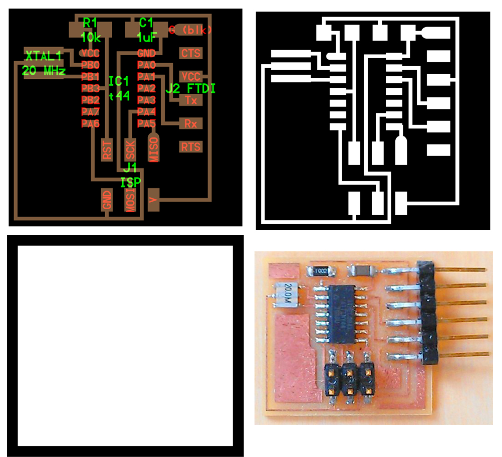
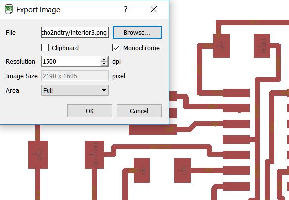 Exporting the monochrome image.
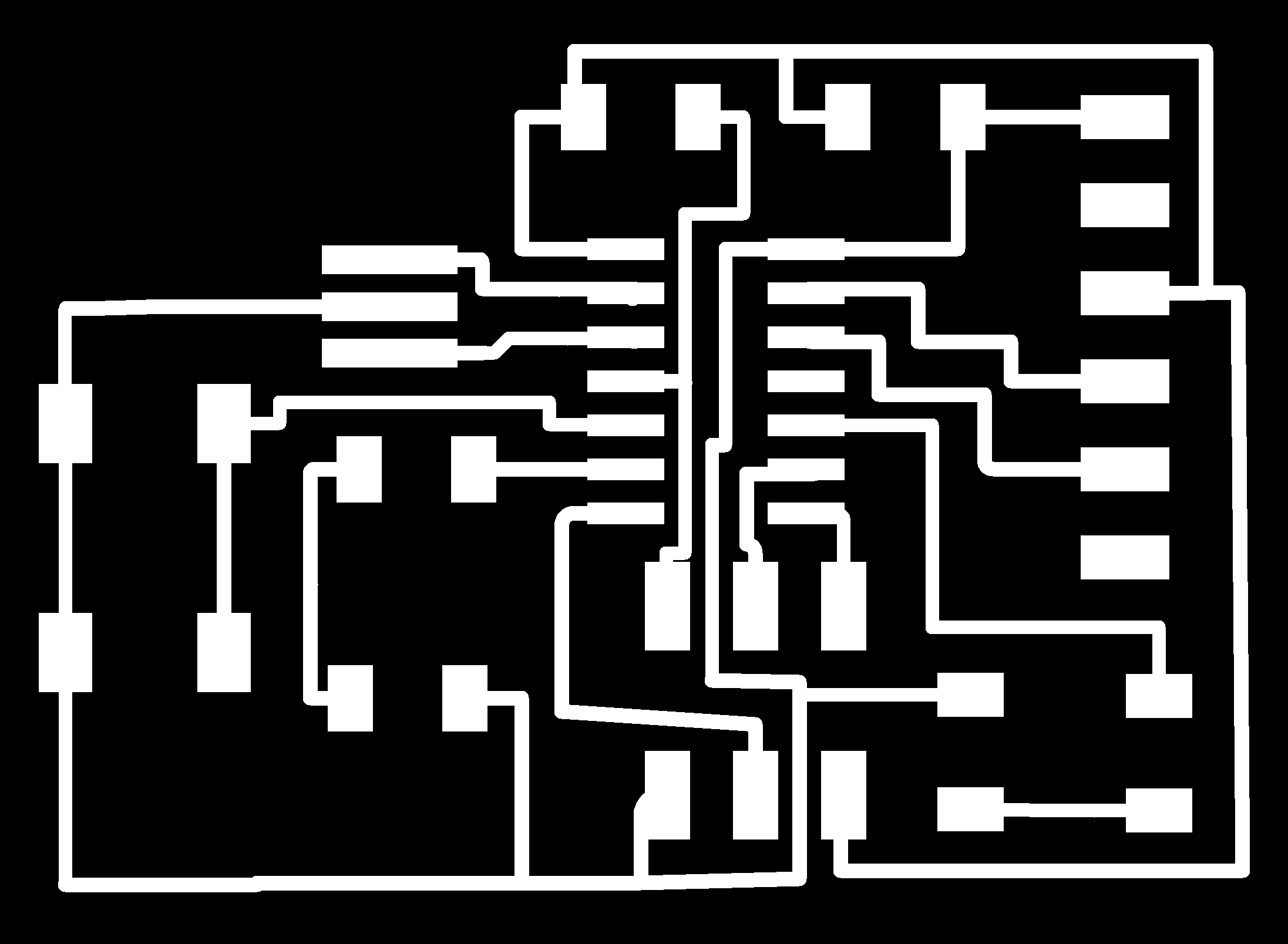 This is the image to introduce in mods, the path of the 1/64 milling cutter, is the inverse that gives you when exporting the image.
8. Make the frame for cutting with the 1/32 cutter
For the frame image I used photoshop to create a frame around.
 I added in photoshop a diameter of cutter "1/32" to each side of the canvas to create the cutting frame to the outside of the image, the path of the 1/64 cutter I deleted it.
PROBLEMS:
With this I thought I had it finished, but I did not realize that I had some faults:
In schematic:
I noticed these errors when I checked the schematic errors.
1. The schematic was not right, I had to connect the switch with the microcontroller on one side and not putting a resistor did not have to connect with vcc
2. I also failed to connect the led to vcc and not to the microcontroller
3. I added a led to the other port since I had enough space where I had placed the switch before.
4. I drew the frame with net instead of with line then it gave me error to have cables by the perimeter.
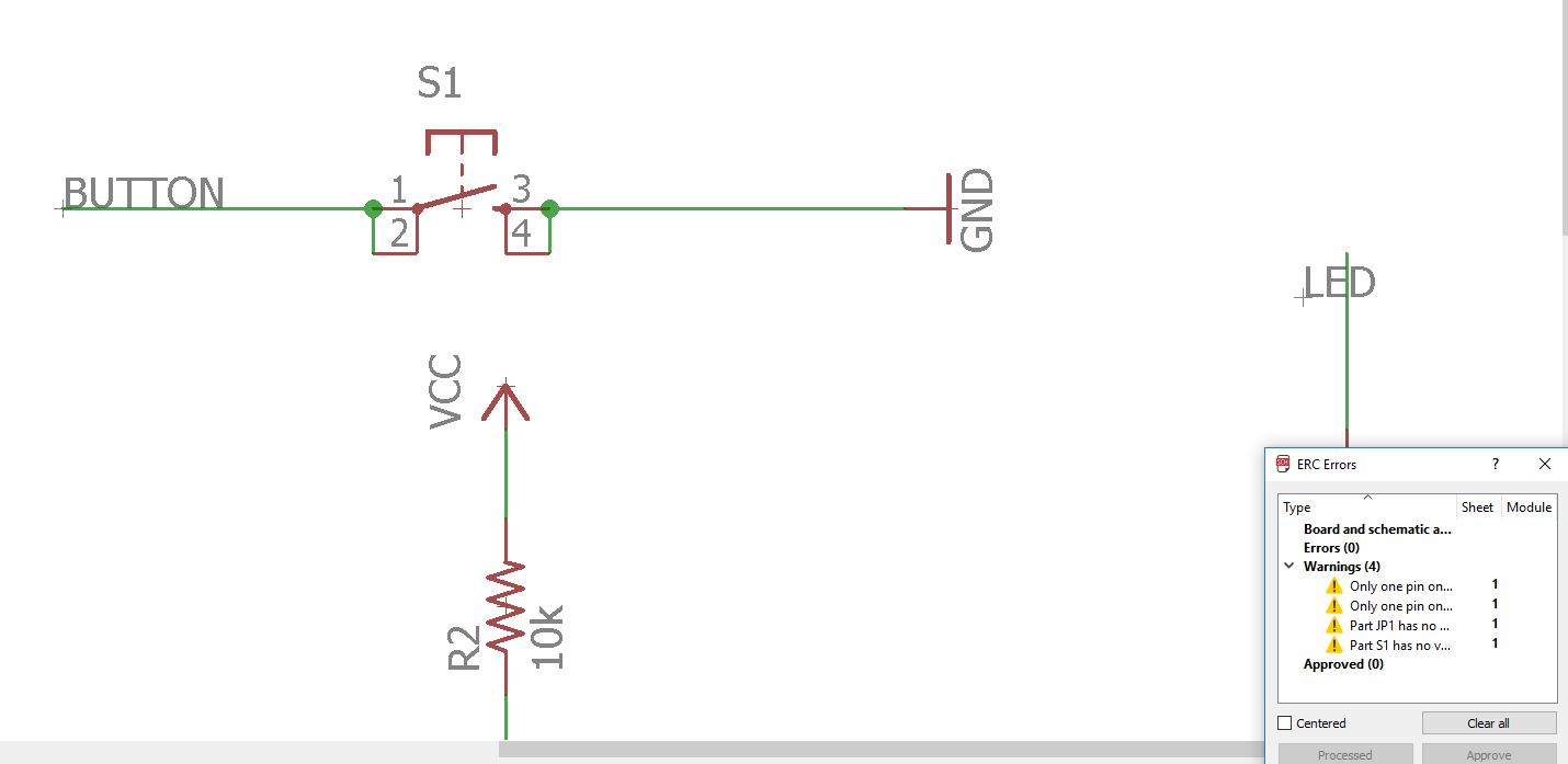 Fixing the button error.
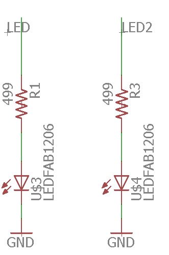 adding other led.
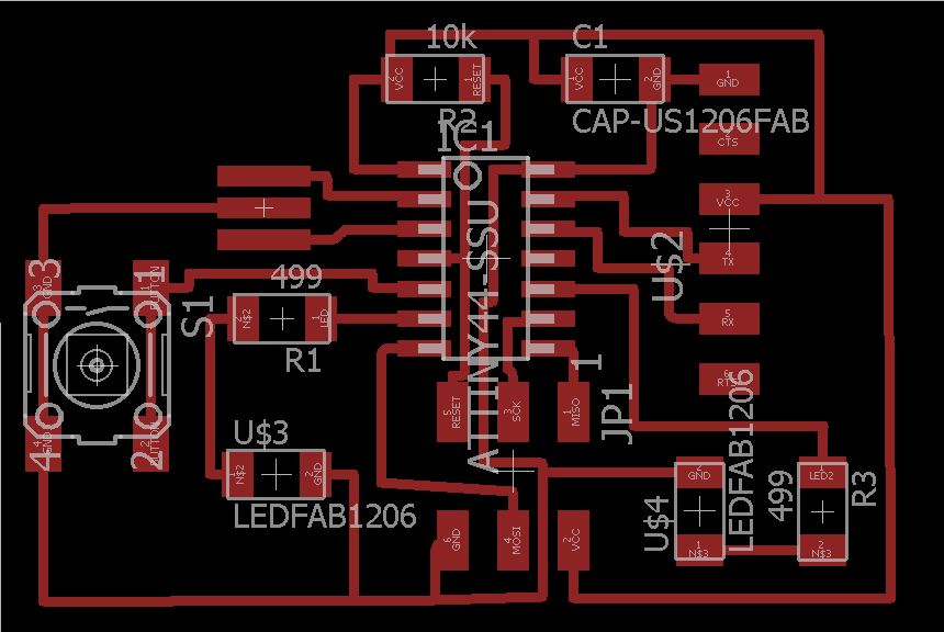 the design of my board.
In the design of the board:
the design of my board.
In the design of the board:
1. The width with which I drew the wires, was too wide about 16 thousand, so when I drew between the plates it gave me a distance error in the design rules.
2. Some components were not fully connected.
3. I made adjustments so that there was more separation between the cables.
This are the final results.
 no errors in the checking of DRU.
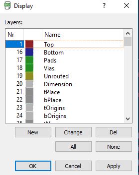 choosing the layers that I want to print.
Interior.
Exterior.
choosing the layers that I want to print.
Interior.
Exterior.
I have had many problems, first with the space between the wire and the pads.9. Send to fab mods for milling in model.
Second, using mods.cba, in the firefox browser it works pretty bad and slow.
With better and faster chrome.
Third, when I sent the file to mods to calculate, I would join some pads although the DRU had them well and no error in the check.
I had problems milling when I cut because I had to do it twice
For milling in fab mods I always will follow this steps:
1. Prepare png traces and frame files.
To see how they are prepared click here:
2. Start the mdx-20 model and enable the port in ubuntu.
The Steps are similar than in the week 4 Electronic production.
- Turn on the machine and bring the spindle to the origin,
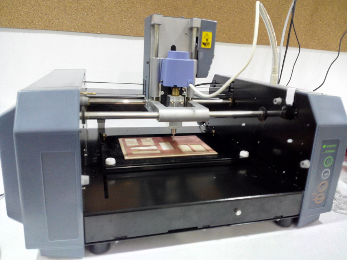
The milling machine Roland Mill MdX-20.
It will depend on the operating system and type of machine you use, in this case you did it by accessing a file that was in the ubuntu home folder from the ubuntu command console. Fabmods / serial
At the time a message appeared saying that the port was open and this enabled the send and that information passed through the cable to the mdx-20 machine
3. Get into fab mods and import the png file.
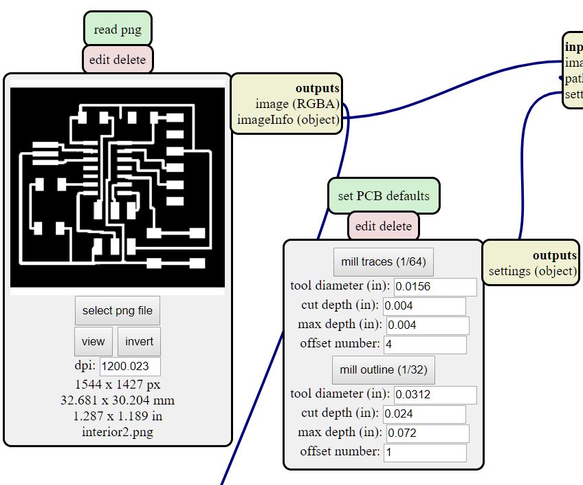
4. Choose the type of cutter 1/64 for the traces and 1/32 to cut the frame.
I choose the type of cutter I'm going to use and adjust the parameters I want the tool to have, such as offset and cut depth.
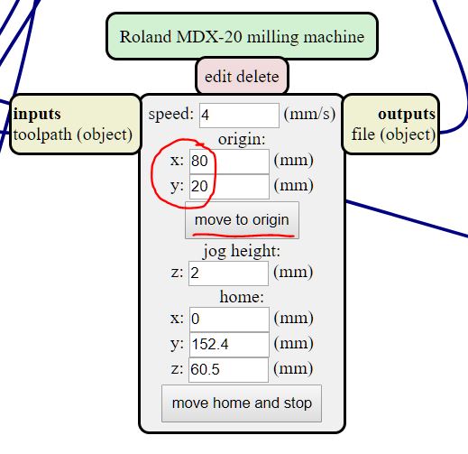
5. Place the cutter in the machine and adjust the origin.
I move the machine to the cutting source to position the cutter and adjust it to the point where the cut begins.
I carefully take the end mill out of its sheath and place it without touching the tip on the spindle of the machine.
- Change and place the milling cutter on the winch.
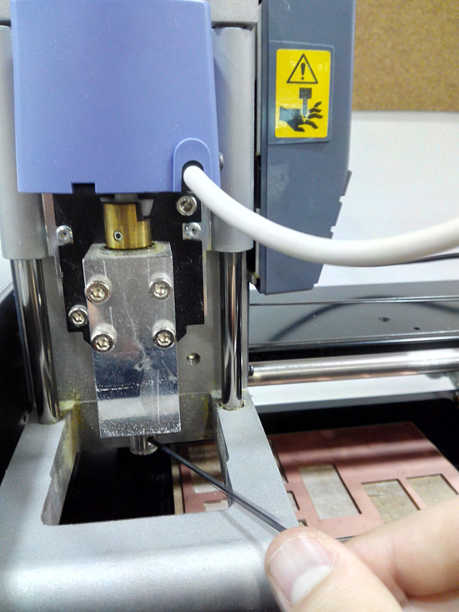
adjusting the cutter.
- Place the cutter on the z axis near the board to be engraved.
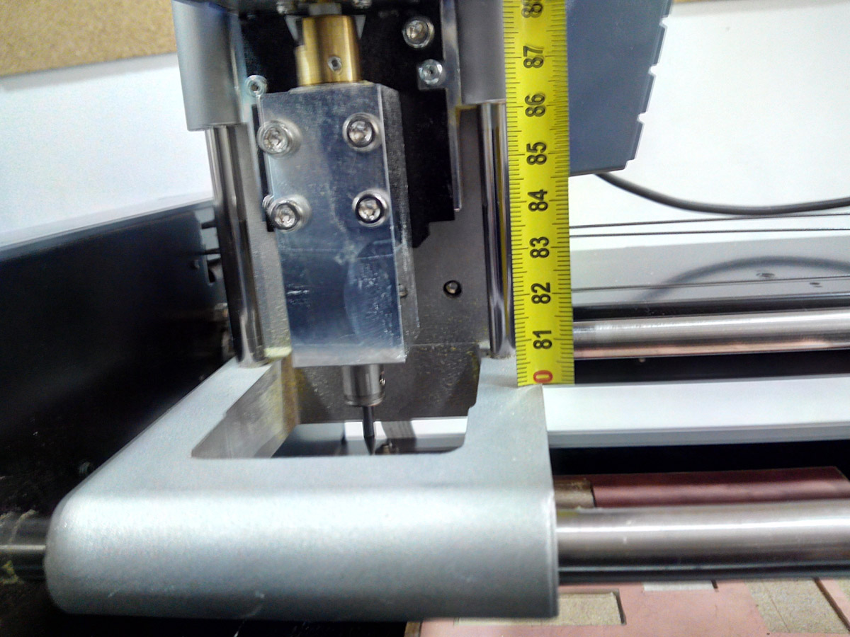
Lowering the cutter 5 mm from the stop for safety.
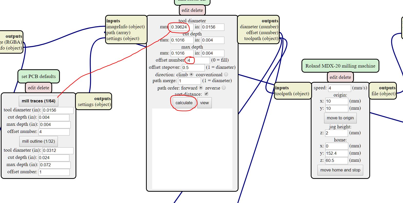
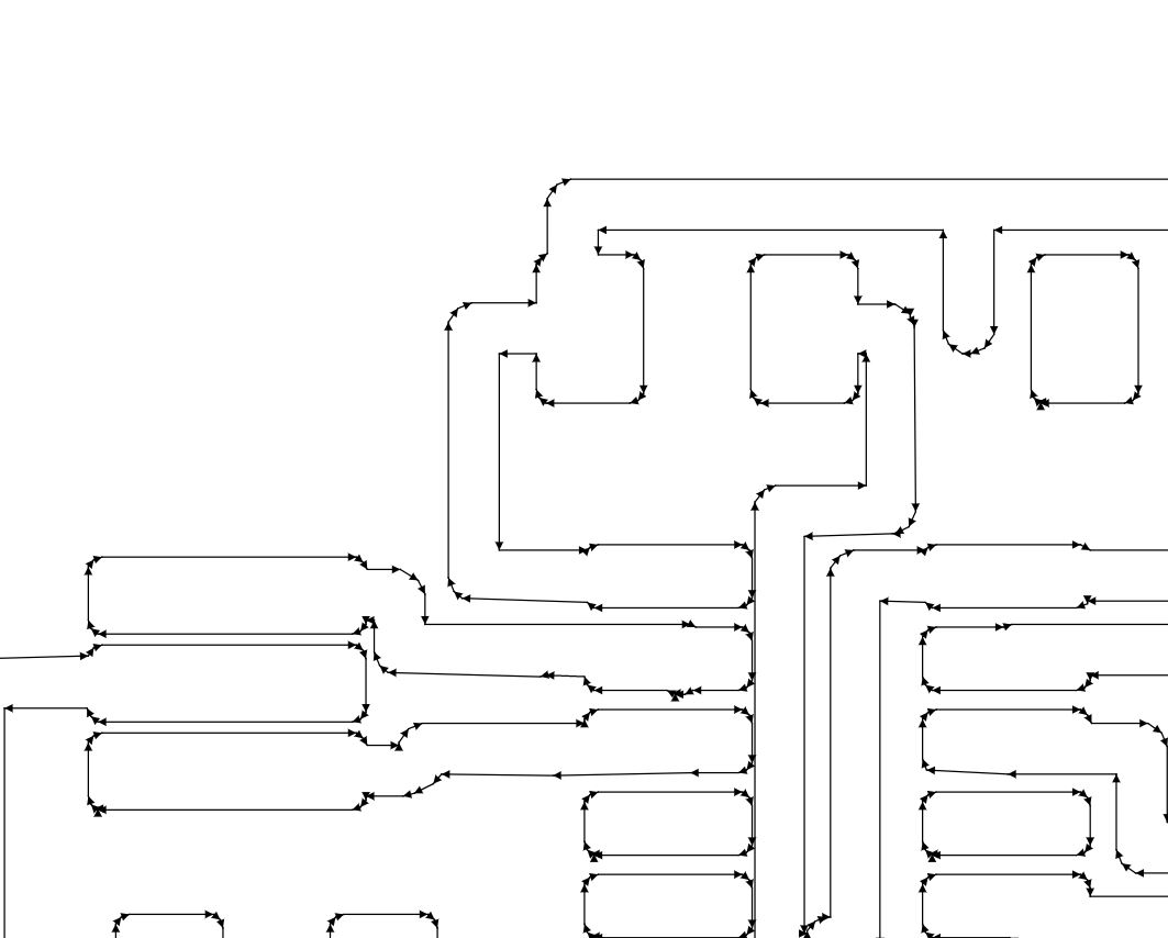
6. Calculate the path of the tool, check that no traces are joined (if the design rules are correct there should be no failure).
With the calculate key, a new window will open where you can see the path of the tool and when you finish calculating the path will turn blue.
Particular attention must be paid to areas where the traces are very close together.
7. Send to mill and monitor the process.
Pressing send verifying that the origin is where it has to be and that the milling cutter will have enough space to do it in the material that places
8. Repeat the steps with the frame.
Once the inner part is milled, I insert the image of the frame and recalculate the path, choosing this time the 1/32 milling cutter
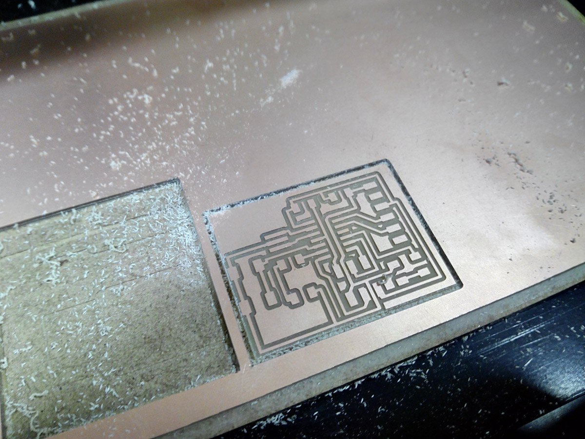
Milling the board
soldering and testing
Once it has been milled successfully, it is now time to solder
Carefully solder the components and check the continuity of the entire board.
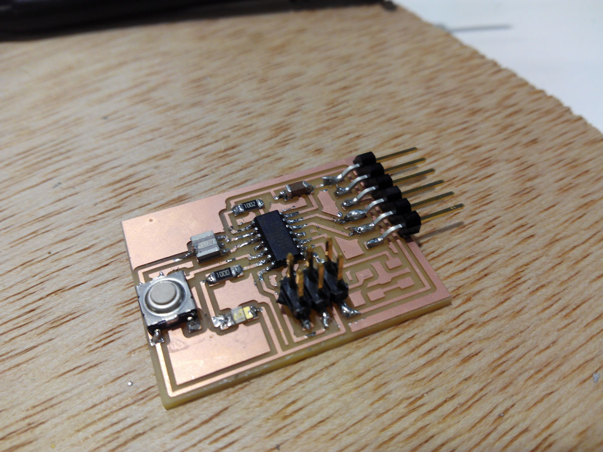
Soldering the components in the correct place.
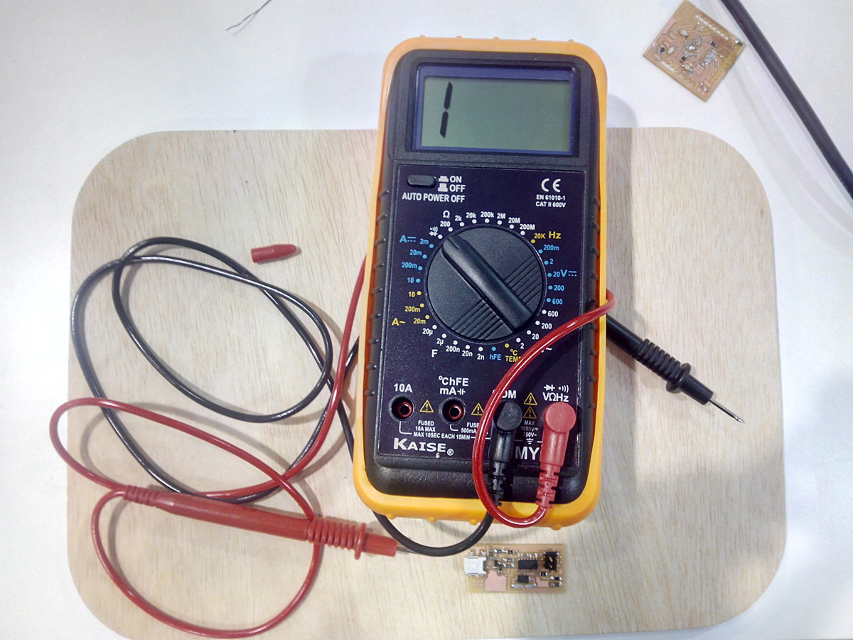
Measure the continuity with the voltmeter and check the microprocessor pins and the GND and VCC, then the other components.
Testing the board
Programming:
Following the tutorial of the Fab ISP it is necessary to remove 2 resistances for the Fab ISP to function like the programmer of the new plate and to connect it in series to the new one.
First we do what the tutorial says and desolder 2 resistances
Then we connect the FAB ISP correctly to the pins of the other board and once they are well connected we go to Arduino:
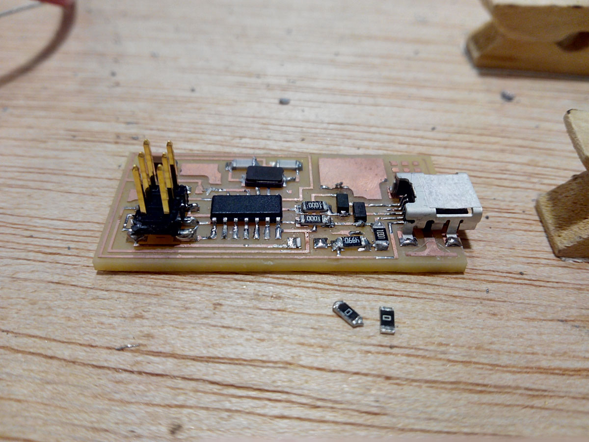
Preparing the fab isp to programing
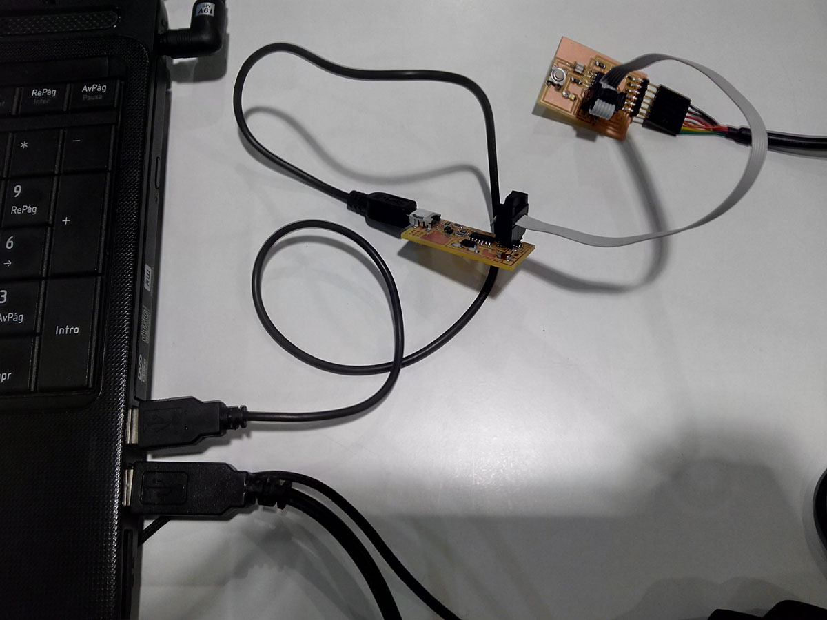
Connecting the fab isp and the hello-echo at the laptop
ARDUINO.
In order for the board to be programmed it is necessary to select the type of microcontroller, Attiny 45 the programmed FAB ISP the external crystal of 20 mhz and once we have everything we apply the bootloader, if all is well our board will be ready to be programmed.

The program its Arduino 1.8.1 Portable version.
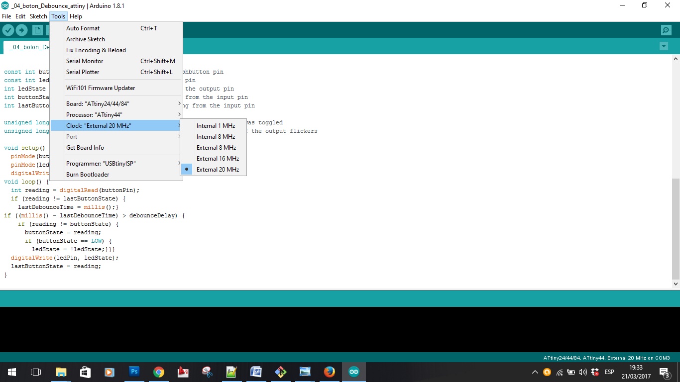
Choosing the attiny44 components.
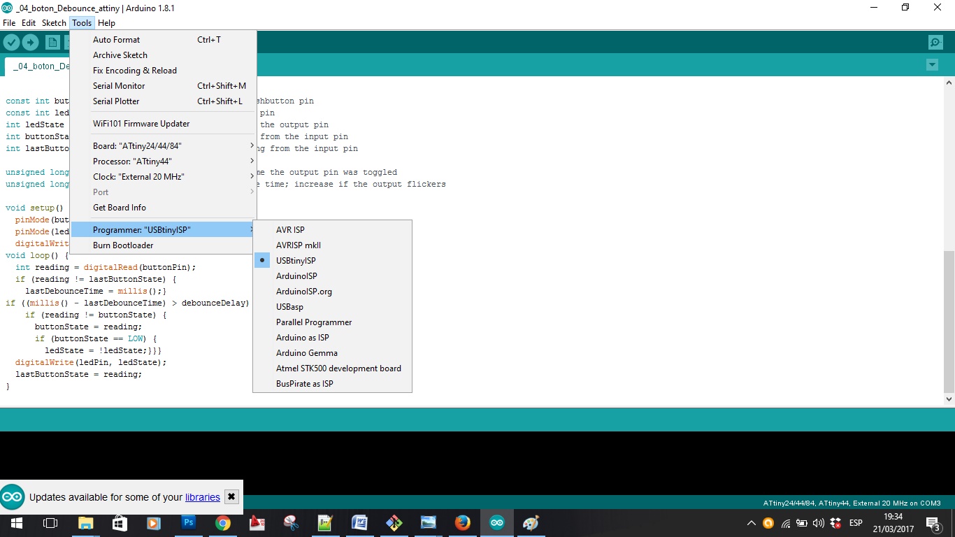
Choosing the Programmer FabISP
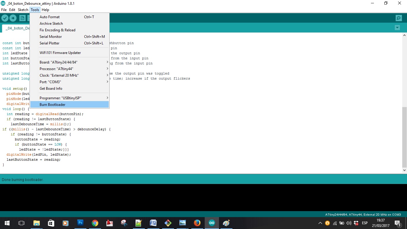
Making the bootloader
NOW THE HELLO-ECHO IS READY TO BE PROGRAMMED.
test it:
To do the test first in c, open the Neil program to do the test it, open a new file in arduino. Then I open a new tab with the name followed by .c and paste the code in Neil's c.
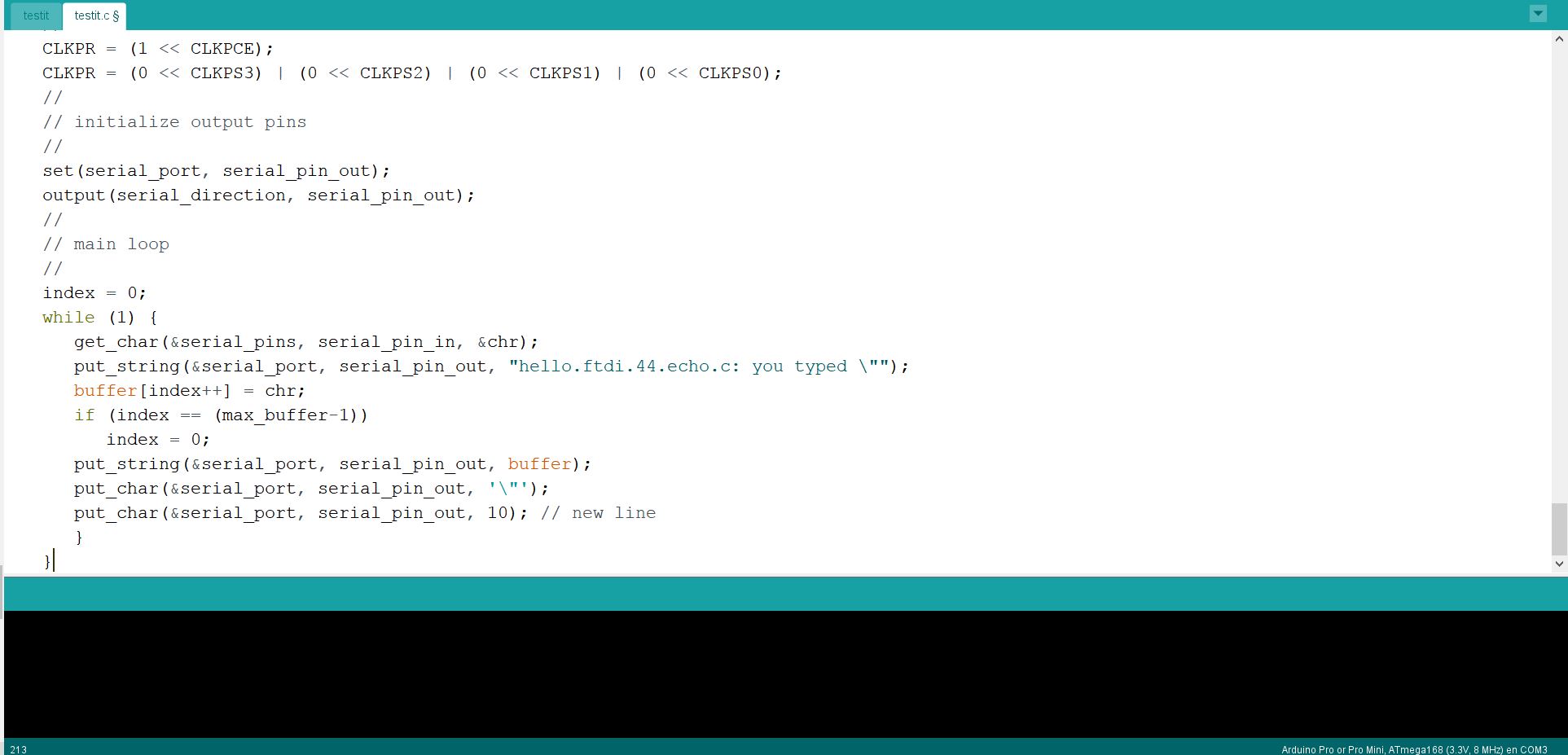
Neil .c program in arduino.
I compile and check that it is well.
With hello44 and fab isp connected to it, I upload the programming and see what happens on the serial monitor.
//
//
// hello.ftdi.44.echo.c
//
// 115200 baud FTDI character echo, with flash string
//
// set lfuse to 0x5E for 20 MHz xtal
//
// Neil Gershenfeld
// 12/8/10
//
// (c) Massachusetts Institute of Technology 2010
// This work may be reproduced, modified, distributed,
// performed, and displayed for any purpose. Copyright is
// retained and must be preserved. The work is provided
// as is; no warranty is provided, and users accept all
// liability.
//

#include <avr/io.h>
#include <util/delay.h>
#include <avr/pgmspace.h>

#define output(directions,pin) (directions |= pin) // set port direction for output
#define set(port,pin) (port |= pin) // set port pin
#define clear(port,pin) (port &= (~pin)) // clear port pin
#define pin_test(pins,pin) (pins & pin) // test for port pin
#define bit_test(byte,bit) (byte & (1 << bit)) // test for bit set
#define bit_delay_time 8.5 // bit delay for 115200 with overhead
#define bit_delay() _delay_us(bit_delay_time) // RS232 bit delay
#define half_bit_delay() _delay_us(bit_delay_time/2) // RS232 half bit delay
#define char_delay() _delay_ms(10) // char delay

#define serial_port PORTA
#define serial_direction DDRA
#define serial_pins PINA
#define serial_pin_in (1 << PA0)
#define serial_pin_out (1 << PA1)

#define max_buffer 25

void get_char(volatile unsigned char *pins, unsigned char pin, char *rxbyte) {
   //
   // read character into rxbyte on pins pin
   //    assumes line driver (inverts bits)
   //
   *rxbyte = 0;
   while (pin_test(*pins,pin))
      //
      // wait for start bit
      //
      ;
   //
   // delay to middle of first data bit
   //
   half_bit_delay();
   bit_delay();
   //
   // unrolled loop to read data bits
   //
   if pin_test(*pins,pin)
      *rxbyte |= (1 << 0);
   else
      *rxbyte |= (0 << 0);
   bit_delay();
   if pin_test(*pins,pin)
      *rxbyte |= (1 << 1);
   else
      *rxbyte |= (0 << 1);
   bit_delay();
   if pin_test(*pins,pin)
      *rxbyte |= (1 << 2);
   else
      *rxbyte |= (0 << 2);
   bit_delay();
   if pin_test(*pins,pin)
      *rxbyte |= (1 << 3);
   else
      *rxbyte |= (0 << 3);
   bit_delay();
   if pin_test(*pins,pin)
      *rxbyte |= (1 << 4);
   else
      *rxbyte |= (0 << 4);
   bit_delay();
   if pin_test(*pins,pin)
      *rxbyte |= (1 << 5);
   else
      *rxbyte |= (0 << 5);
   bit_delay();
   if pin_test(*pins,pin)
      *rxbyte |= (1 << 6);
   else
      *rxbyte |= (0 << 6);
   bit_delay();
   if pin_test(*pins,pin)
      *rxbyte |= (1 << 7);
   else
      *rxbyte |= (0 << 7);
   //
   // wait for stop bit
   //
   bit_delay();
   half_bit_delay();
   }

void put_char(volatile unsigned char *port, unsigned char pin, char txchar) {
   //
   // send character in txchar on port pin
   //    assumes line driver (inverts bits)
   //
   // start bit
   //
   clear(*port,pin);
   bit_delay();
   //
   // unrolled loop to write data bits
   //
   if bit_test(txchar,0)
      set(*port,pin);
   else
      clear(*port,pin);
   bit_delay();
   if bit_test(txchar,1)
      set(*port,pin);
   else
      clear(*port,pin);
   bit_delay();
   if bit_test(txchar,2)
      set(*port,pin);
   else
      clear(*port,pin);
   bit_delay();
   if bit_test(txchar,3)
      set(*port,pin);
   else
      clear(*port,pin);
   bit_delay();
   if bit_test(txchar,4)
      set(*port,pin);
   else
      clear(*port,pin);
   bit_delay();
   if bit_test(txchar,5)
      set(*port,pin);
   else
      clear(*port,pin);
   bit_delay();
   if bit_test(txchar,6)
      set(*port,pin);
   else
      clear(*port,pin);
   bit_delay();
   if bit_test(txchar,7)
      set(*port,pin);
   else
      clear(*port,pin);
   bit_delay();
   //
   // stop bit
   //
   set(*port,pin);
   bit_delay();
   //
   // char delay
   //
   bit_delay();
   }

void put_string(volatile unsigned char *port, unsigned char pin, char *str) {
   //
   // print a null-terminated string
   //
   static int index;
   index = 0;
   do {
      put_char(port, pin, str[index]);
      ++index;
      } while (str[index] != 0);
   }

int main(void) {
   //
   // main
   //
   static char chr;
   static char buffer[max_buffer] = {0};
   static int index;
   //
   // set clock divider to /1
   //
   CLKPR = (1 << CLKPCE);
   CLKPR = (0 << CLKPS3) | (0 << CLKPS2) | (0 << CLKPS1) | (0 << CLKPS0);
   //
   // initialize output pins
   //
   set(serial_port, serial_pin_out);
   output(serial_direction, serial_pin_out);
   //
   // main loop
   //
   index = 0;
   while (1) {
      get_char(&serial_pins, serial_pin_in, &chr);
      put_string(&serial_port, serial_pin_out, "hello.ftdi.44.echo.c: you typed \"");
      buffer[index++] = chr;
      if (index == (max_buffer-1))
         index = 0;
      put_string(&serial_port, serial_pin_out, buffer);
      put_char(&serial_port, serial_pin_out, '\"');
      put_char(&serial_port, serial_pin_out, 10); // new line
      }
   }
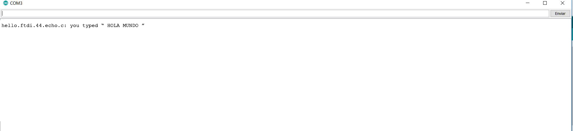
Neil .c program in arduino, monitor serial.
with this program you have to make sure that the mcu returns the information you send to the serial monitor.
In week 8 you can see what I do with this board and the different programs that you can do.
You can download the files below:
FILES:
Hello echo alvaro