Assignments:
- group project: test the design rules for your printer(s)
- design and 3D print an object (small, few cm) that could not be made subtractively
- 3D scan an object (and optionally print it) (extra credit: make your own scanner)
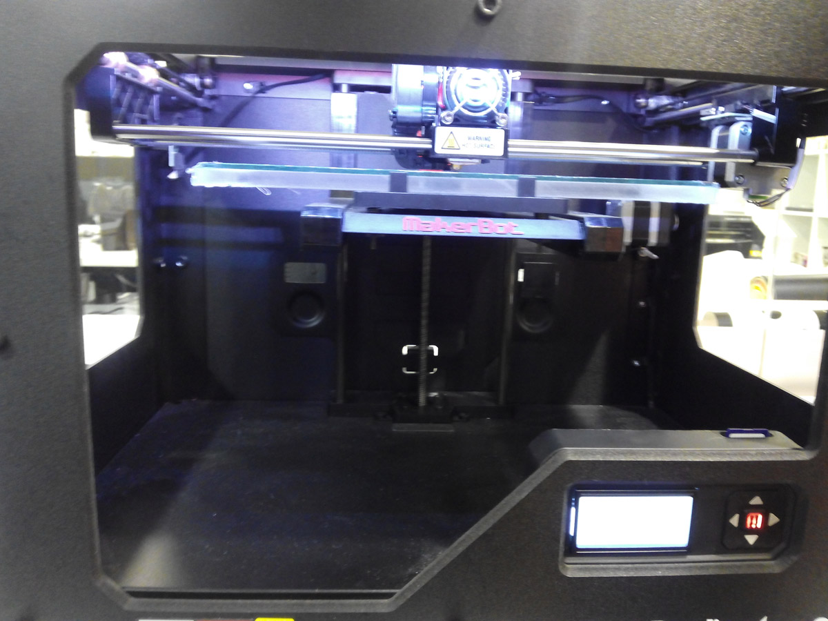
In our lab We work with the Makerbot Replicator 2 is a good quality commercial desktop printer.
 Replicator 2.
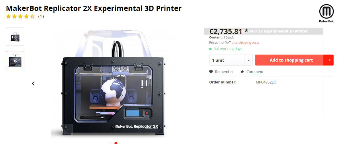 It is no longer available for sale and this is its successor today,Replicator 2x.
--- Steps to use the 3d printer ---
1. Turn the machine on, the extruder moves to the source and waits for instructions.
2. With the menu screen we choose the options that we want, like preheat, load a file..etc.
3. Mount the PLA plastic roll with the stand behind the machine
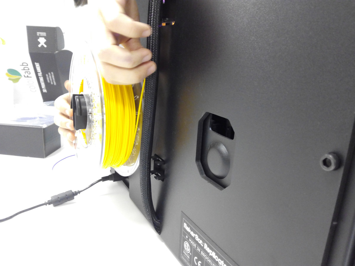 Place the new roll of PLA and load the thread.
4. We select to change material / load
Place the new roll of PLA and load the thread.
4. We select to change material / load
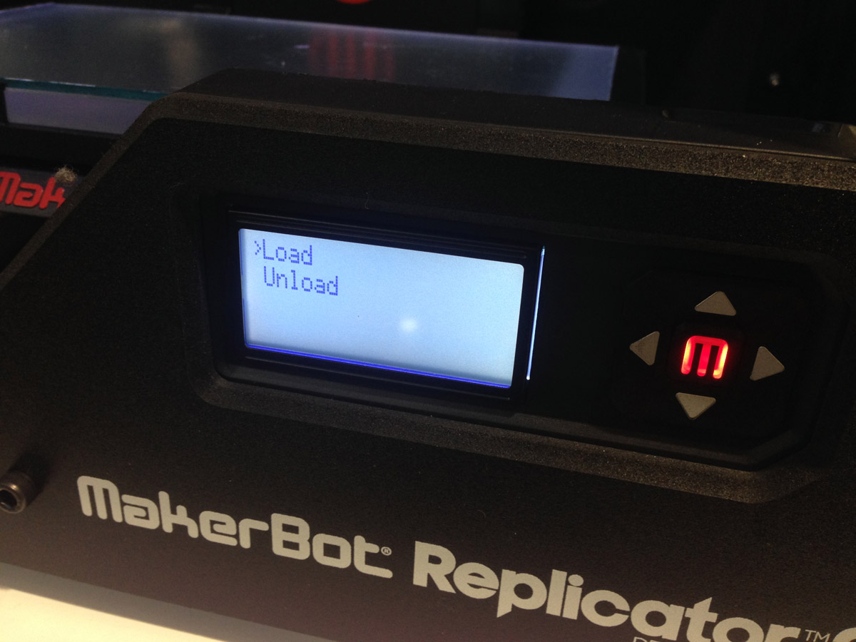 pulse load,to load the new material, the extruder begins to warm.
5. We pass the thread through the guide and place it on the extruder.
pulse load,to load the new material, the extruder begins to warm.
5. We pass the thread through the guide and place it on the extruder.
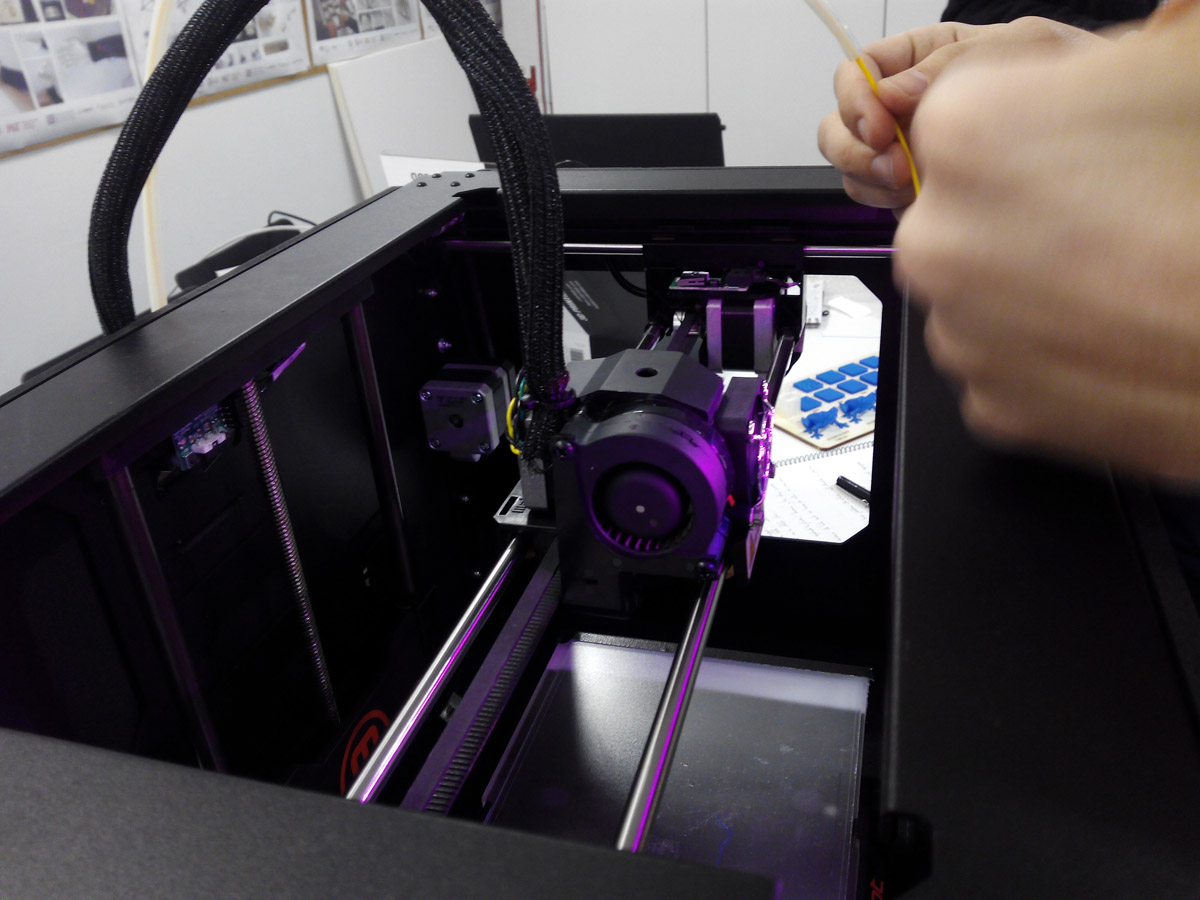 pass the thread through the guide.
6. Wait until the thread comes out of the color we have entered.
pass the thread through the guide.
6. Wait until the thread comes out of the color we have entered.
7. We remove the waste.
8. Remove the tray and pour hair spray so that the piece has a correct fastening, then we put it back
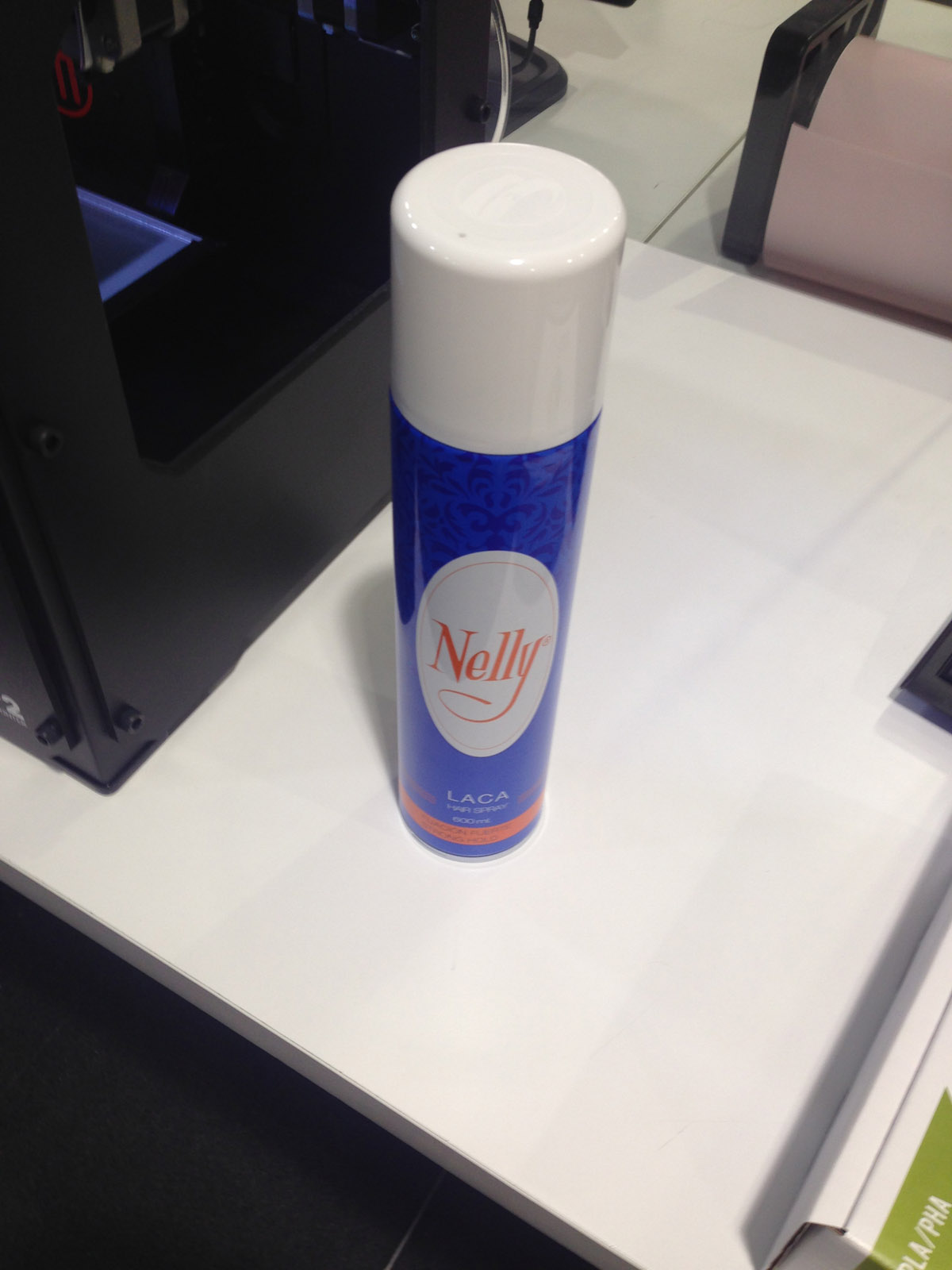 applying hair spray for the piece is better attached to the glass.
9. Insert the memory card with the file previously prepared in makerbotDesktop and select on the screen to print that file.
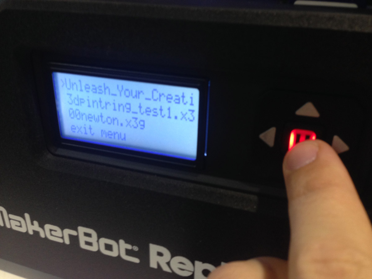 selecting the file.
10. The machine will heat up and begin printing by testing with a line.
selecting the file.
10. The machine will heat up and begin printing by testing with a line.
11. Monitor that everything is okay to pause or cancel work when you feel convenient.
12. Once finished, press enter to start the machine to cool down and remove the tray to remove the print with a spatula.
We use a 3D printer from the makerbot brand that uses the fused-deposition molding technique with this specifications :
-Build volume: 285 x 153 x 155 mm
-Nozzle Diameter: 0.4 mm
-File types: X3G
-Software bundle: MakerBot desktop
-Filament: PLA of 1.75 mm
Here the guide of Makerbot Replicator 2
Makerbot Parameters, explained:
In the Makerbot software, we can configure several types of parameters so that the 3D printer will make more layers or less at a higher or lower temperature and put us raft or not.
The main ones are, layer height, infill, temperature, number of shells, raft, supports:
Layer height: is the amount of material in each layer, if our piece measures 2 cm, the printer will make 100 layers of 0.20 mm.
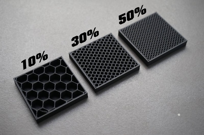
Infill: is the percentage of filling for the inner parts of the piece, the more percentage will have more strength but will waste more material and the printing will be longer..
 Temperature: which will depend on the material, in the datasheet of the material you will find this data, which you can modify..
Number of shells:it is the number of outer layers that you want to have your piece, when the printer finishes them starts with the infill.
Raft: is a base with a pattern that helps the piece to be fastened to the base glass and in the process does not move, it is easily removed.
Supports: are added to the piece to hold parts that fly or with little contact surface and are in danger of collapsing.
--- group project: test the design rules for your printer(s): ---
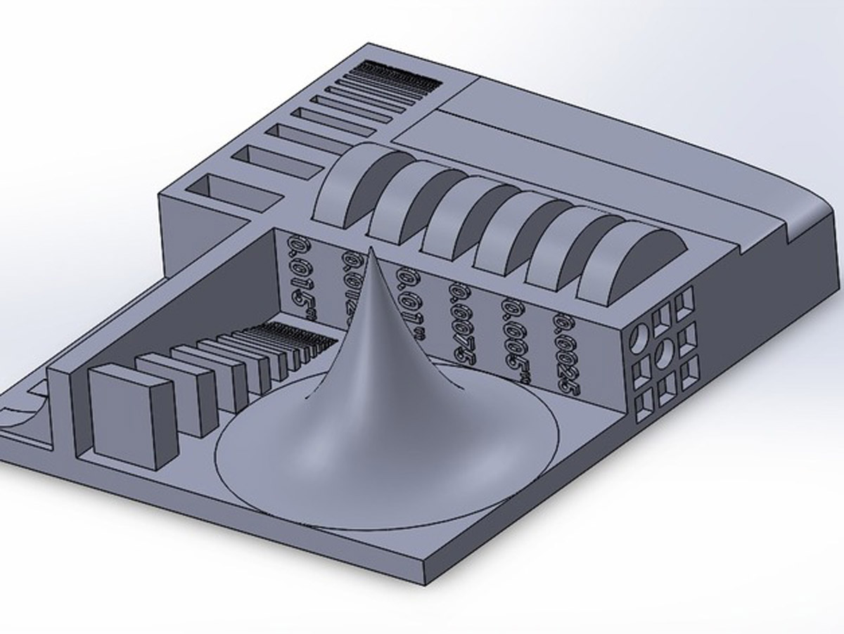
The first thing we did was download a couple of 3d models from the web of thingiverse, the template of constraints
provided by neil and some smaller objects that allowed us to print something fast.
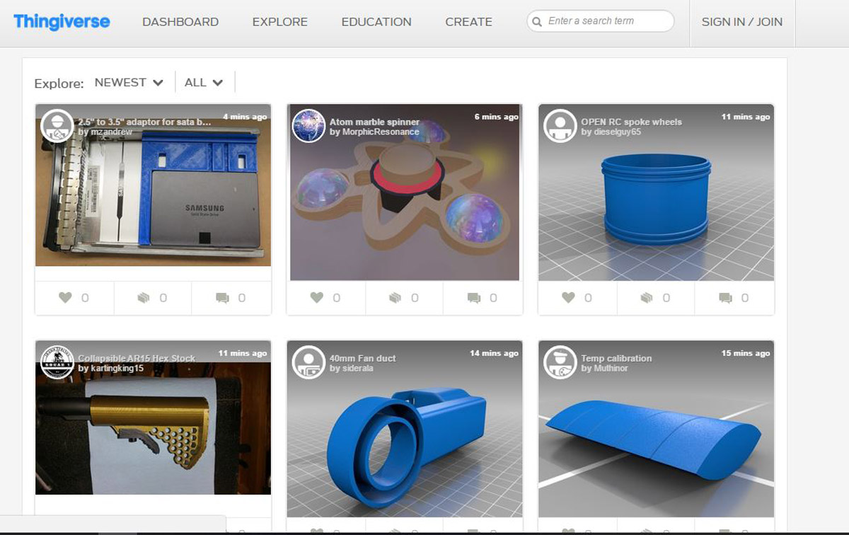
 This was our first impression, we downloaded the STL file and opened Makerbot.
 We prepare the settings and choose low quality and temperature 215ºC
 adding atmega and components of the microcontroller.
 We see that the scale is sufficient and we prepare to print.
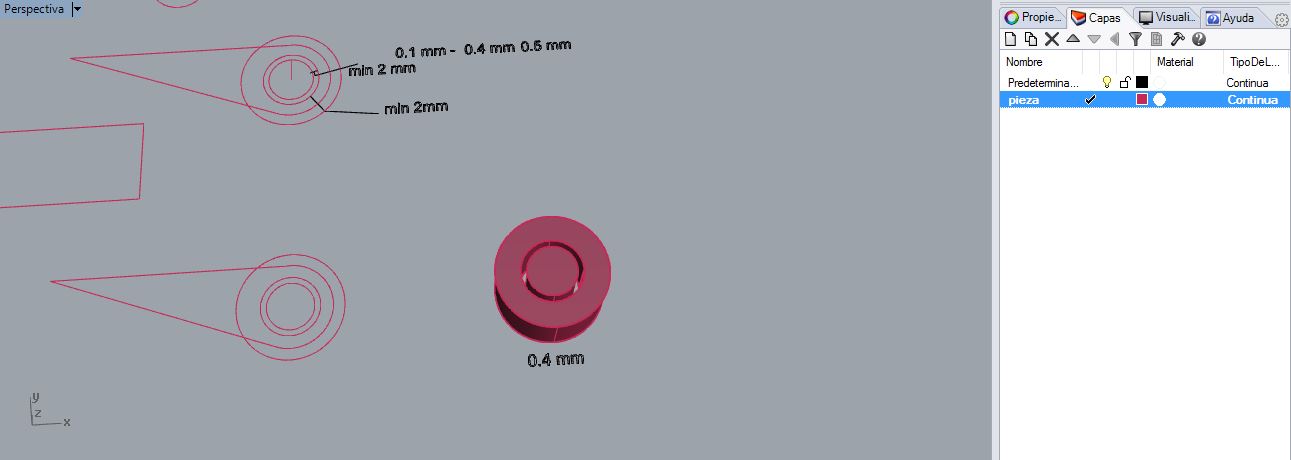
With this model we wanted to know what minimum measures could get to print with that configuration.
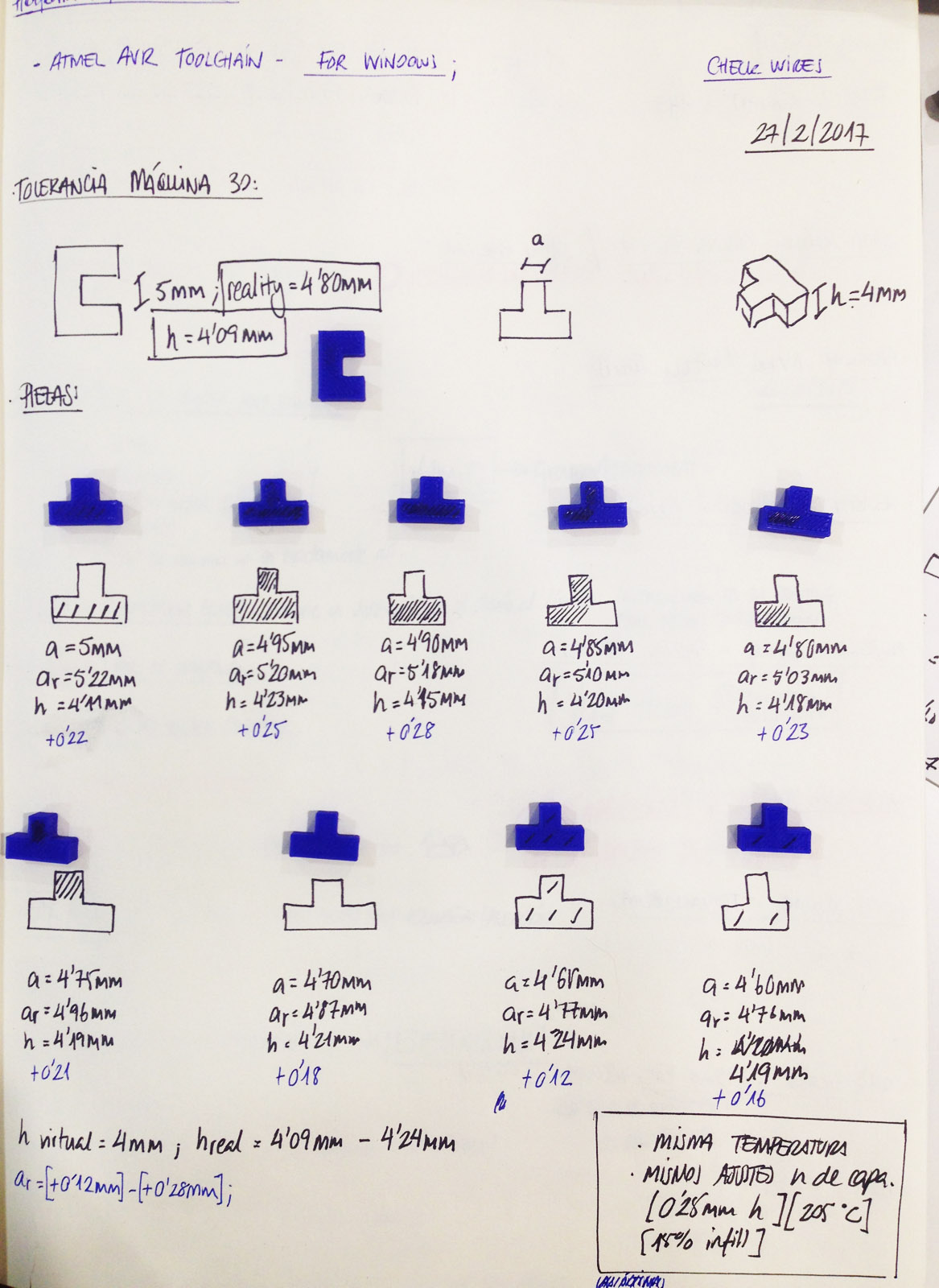
We have also performed kerf press-fit tests and tolerances on the one hand, calculating measures that start to fail and do not fit.

You can see the all group assignment here and see the print parameters.
CLICK THIS LINK ----Group assignment----
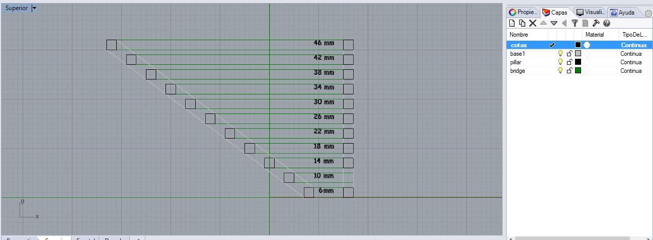
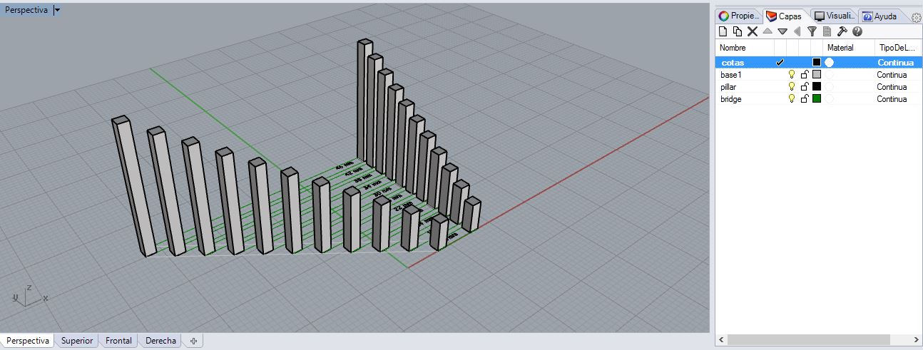
And on the other hand we have realized the following test.
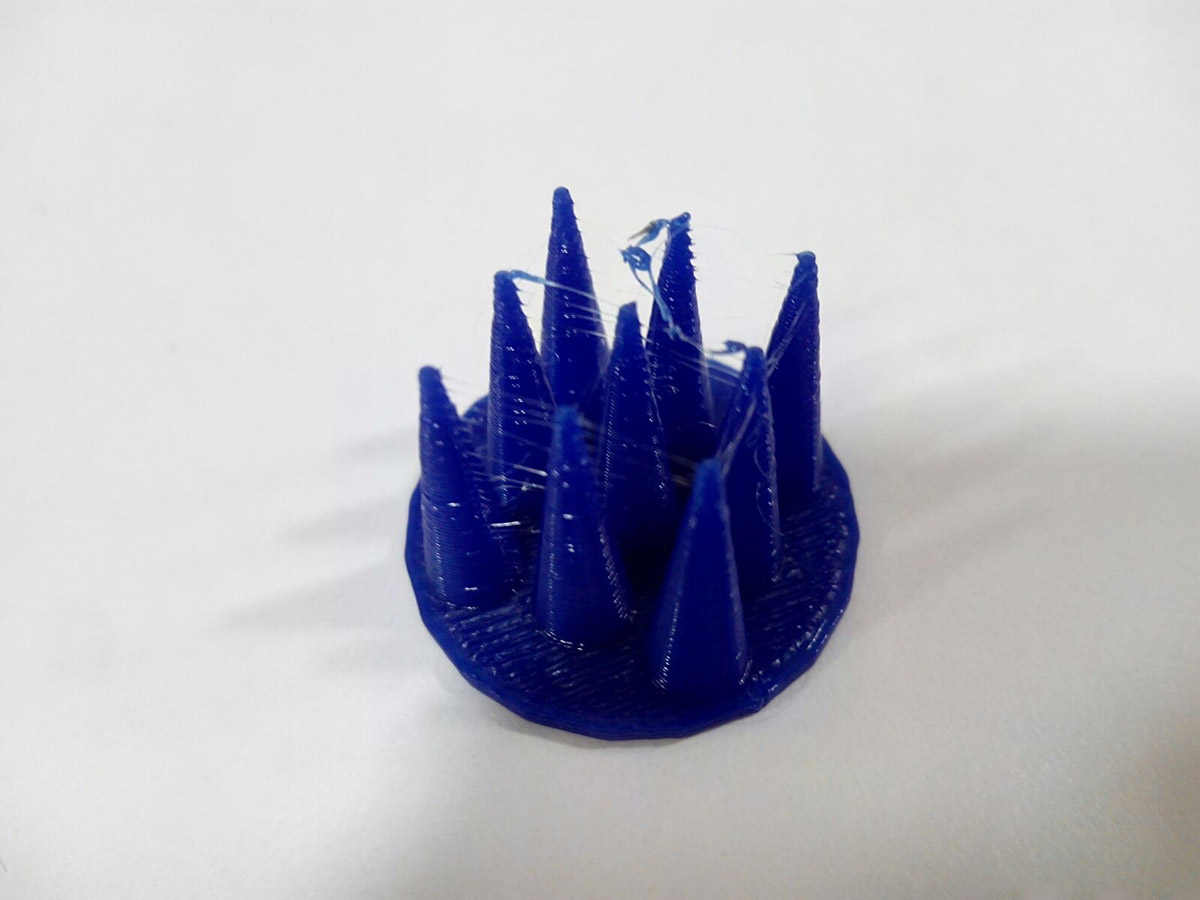
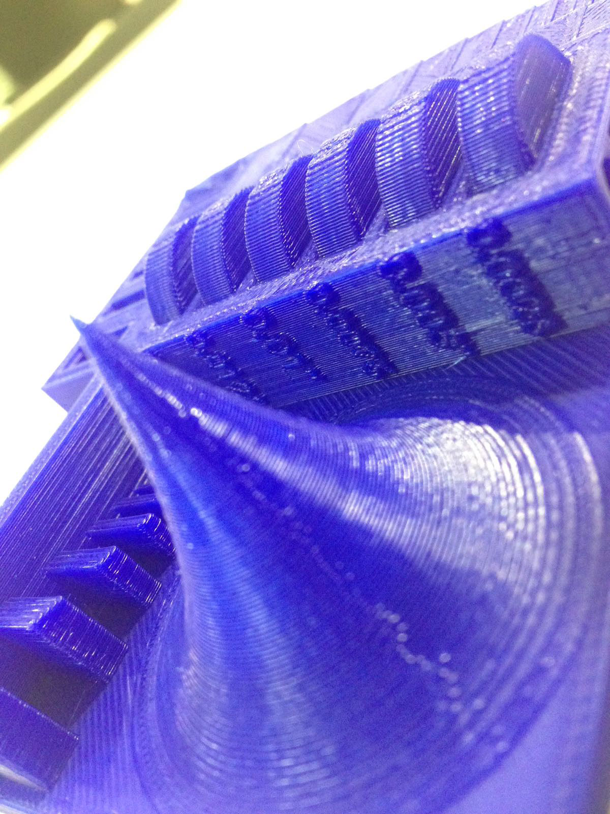
With this test what we want is to know the maximum distance to which cantilever bridges can be made, we design the template in which are added distances of 4mm and grow vertically so if at any time the machine failed, We could stop the machine.
Thus we can also see the buckling of thin structures in this material.
Here the images.
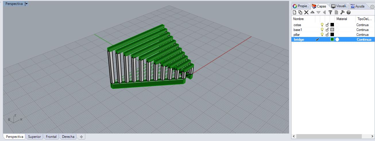 Parameters of Bridges:
Layer height: 0.15 mm
Number of Shells: 2
Extrude Temperature: 210?C
Infill: 15%
Raft: Yes
Suppport: yes
ERROR: To test the bridges I did not consider the parameters that makerbot used to do "bridging":
Makerbot Uses 3 parameters for this:
"bridgeAnchorMinimumLength" / "bridgeAnchorWidth" :
If an anchor region is too narrow or too shallow, it will not provide a large enough base for the end of your bridge.
Here I made my mistake I made the bridge supports too narrow.
"BridgeMaximumLength">
Any object with a bridge-like section longer than the value entered here will not trigger the MakerBot Slicer's bridging settings.>
"BridgeSpacingMultiplier"
The "bridgeSpacingMultiplier" setting offers the opportunity to print those lines closer together, so that they can overlap.
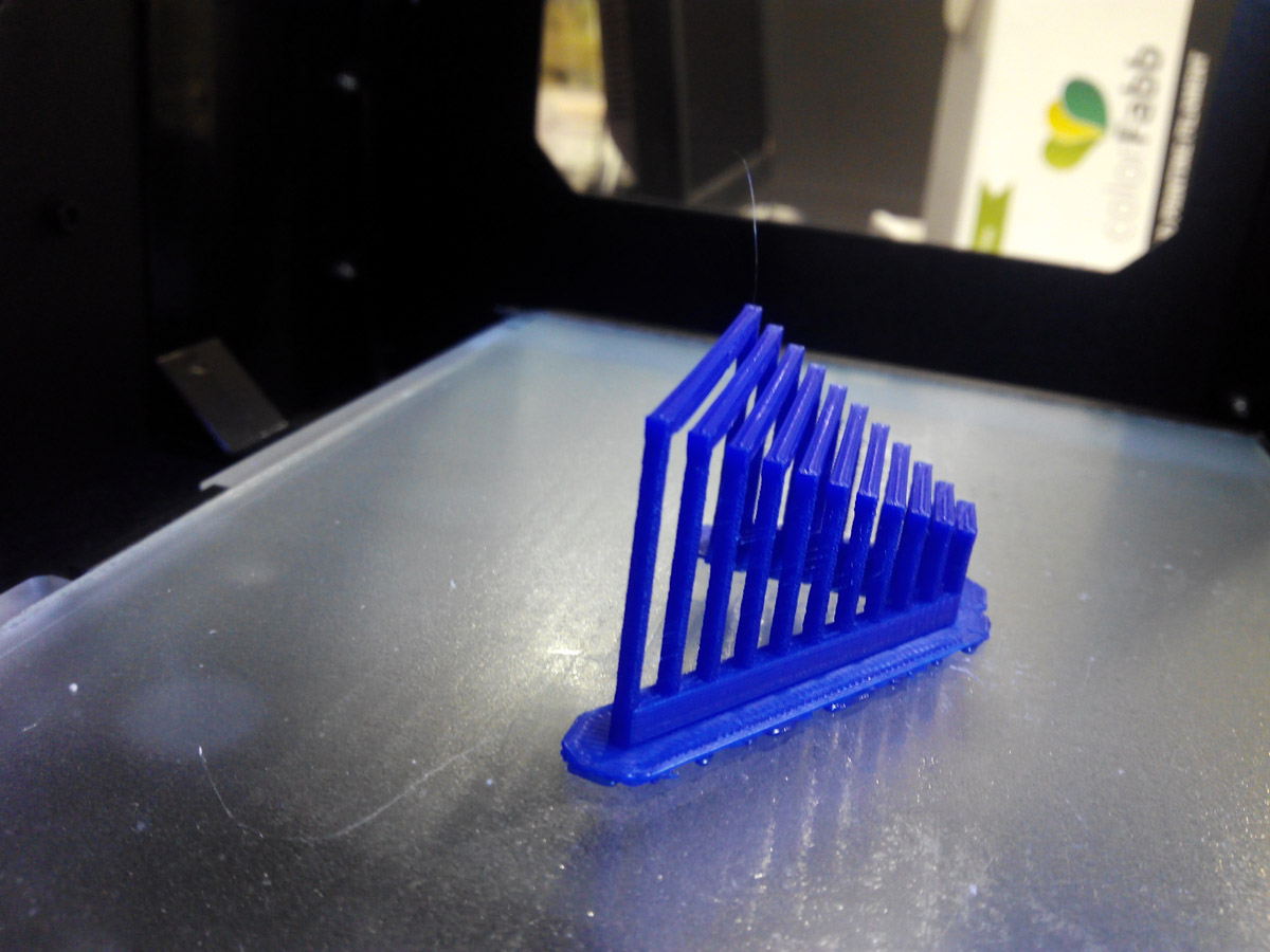
Conclusion:
when bridges are more than 80 mm made it starts to fail.
At 60mm the curve begins to make visible.
The pillars of 2mm from 35 mm in height begin to be very flexible and weak.
Something I learned important is that it usually takes longer to make objects than holes than solid objects with a small infill.
This is because each time it release the thread to move loose and stops, it takes longer than if it release the thread continuously.
In the button with cones, in the base took less time to realize the layers than in the top.
From here we continue doing other tests:
To continue with the theme of exercise 3, I printed a
Raccoon to which I placed a ring to turn it into a key chain.
Layer height: 0.25 mm
Number of Shells: 2
Extrude Temperature: 210?C
Infill: 15%
Raft: Yes
Suppport: yes
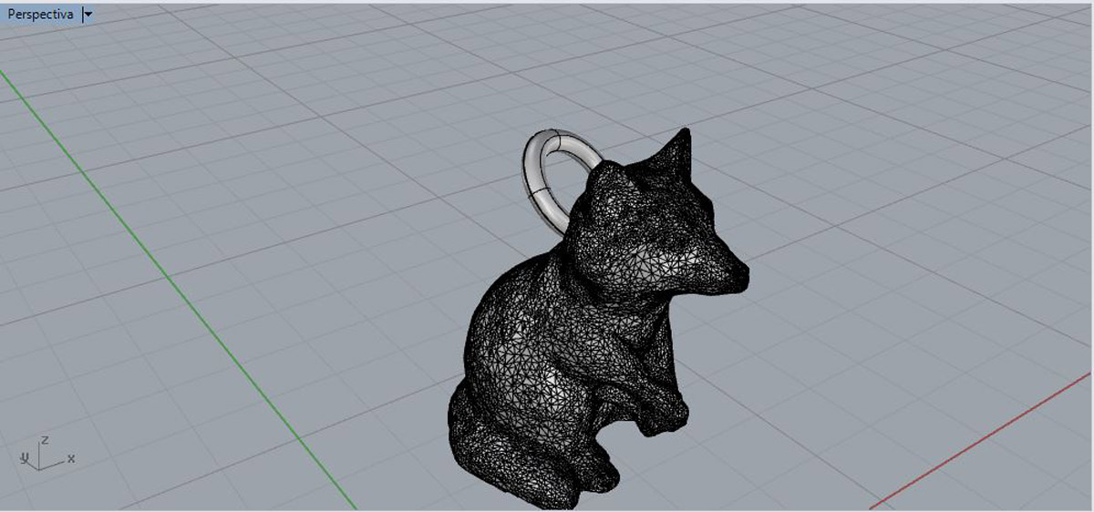 Raccoon with ring, the ring added in rhinoceros and exported to STL .
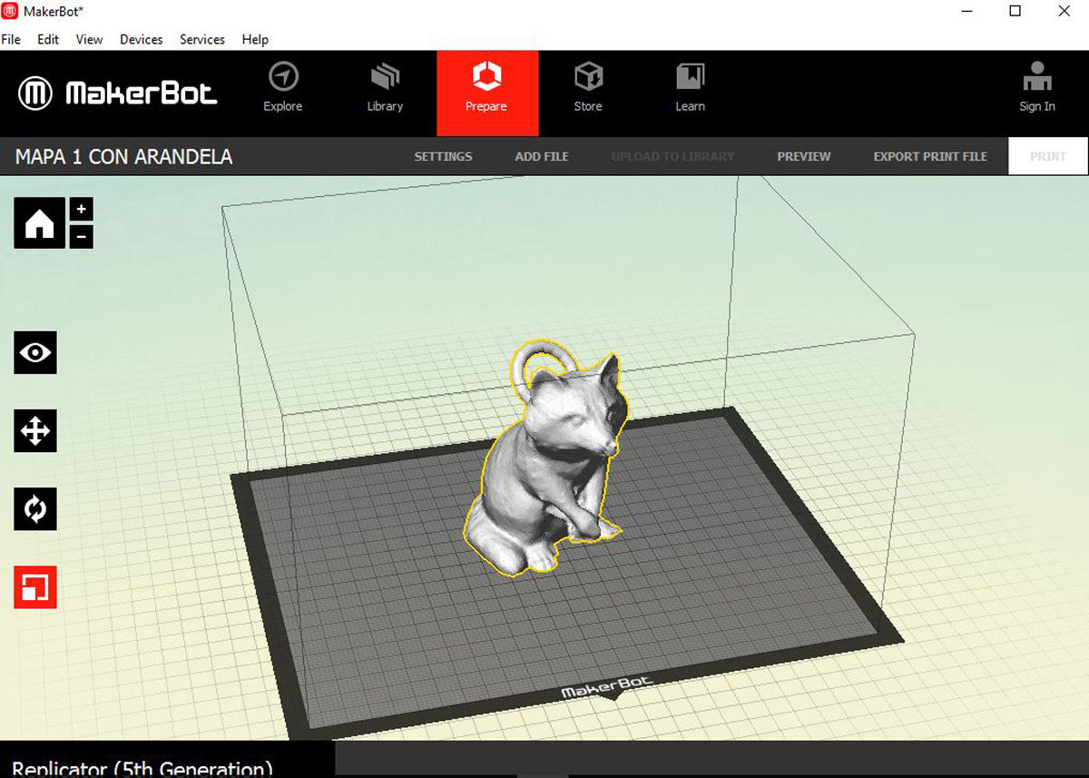 Preparing Raccoon in the maker bot, Scale at 35%.
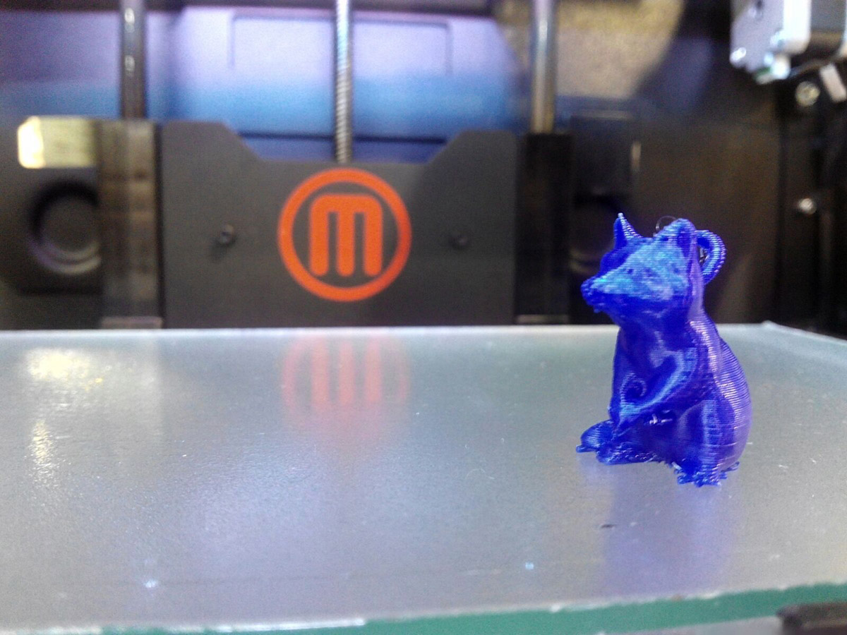 The result.
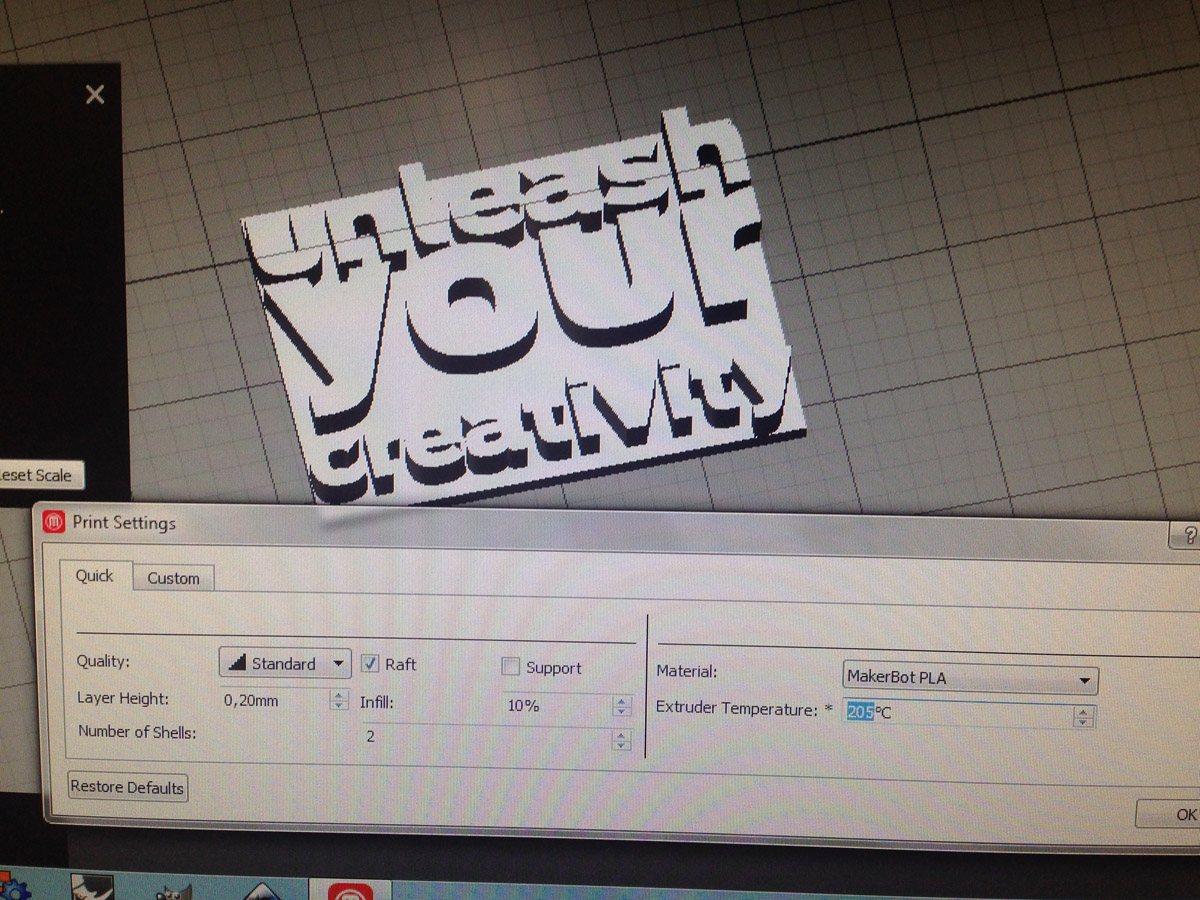
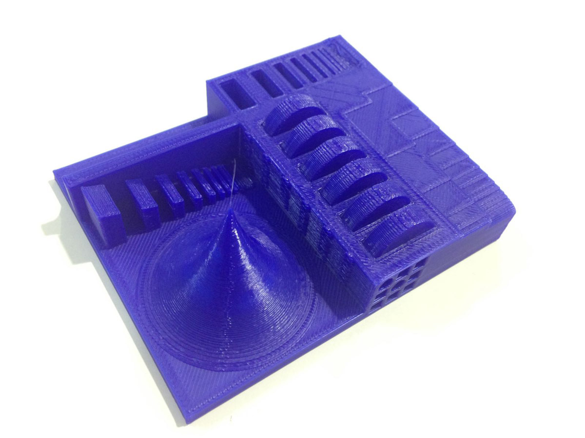
Parameters of the template:
The result.
Parameters of the template:Layer height: 0.30 mm
Number of Shells: 2
Extrude Temperature: 205?C
Infill: 10%
Finally we print the template to see things like scaling, bridges, roughness, cones ... etc.
 You can see more detailed Groupal project in this link: ---- Project group----
Design and 3D print an object (small, few cm) that could not be made subtractively
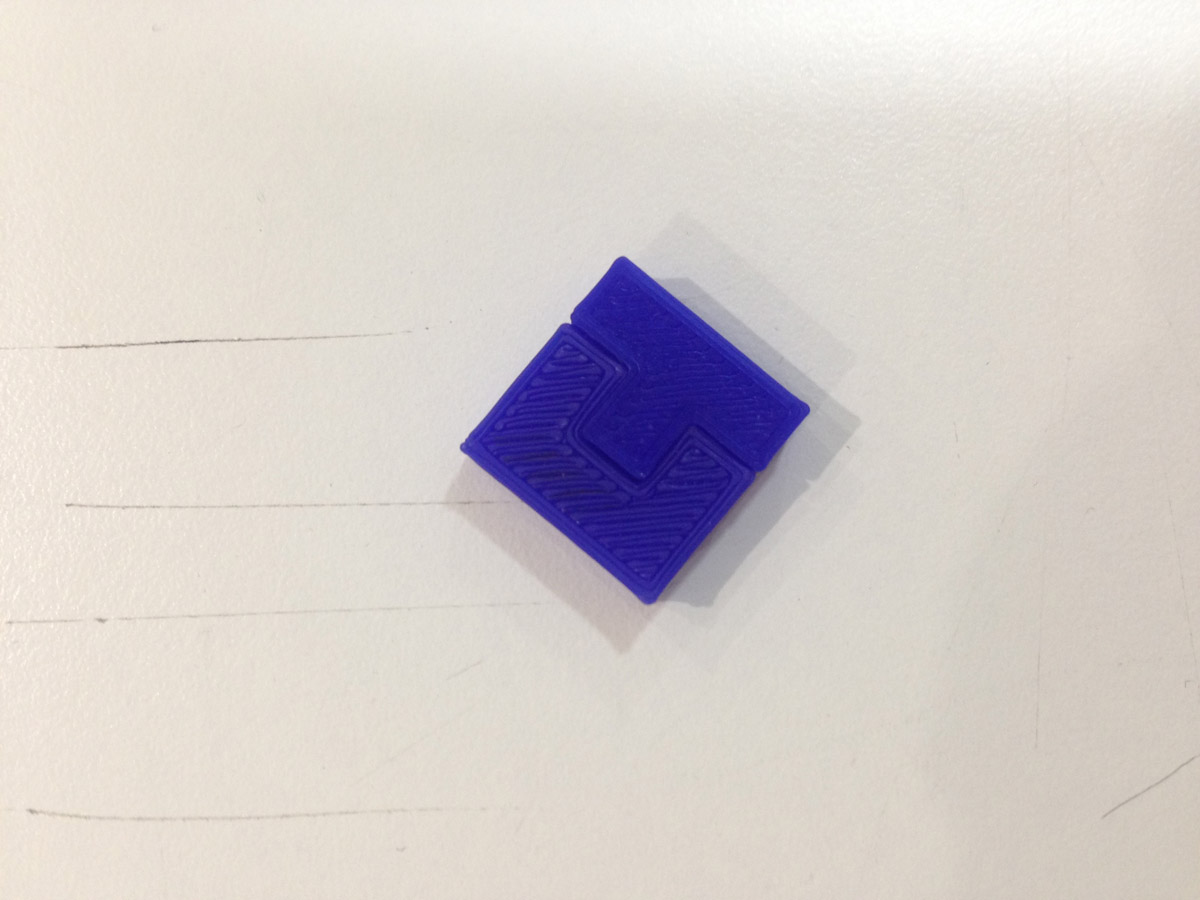
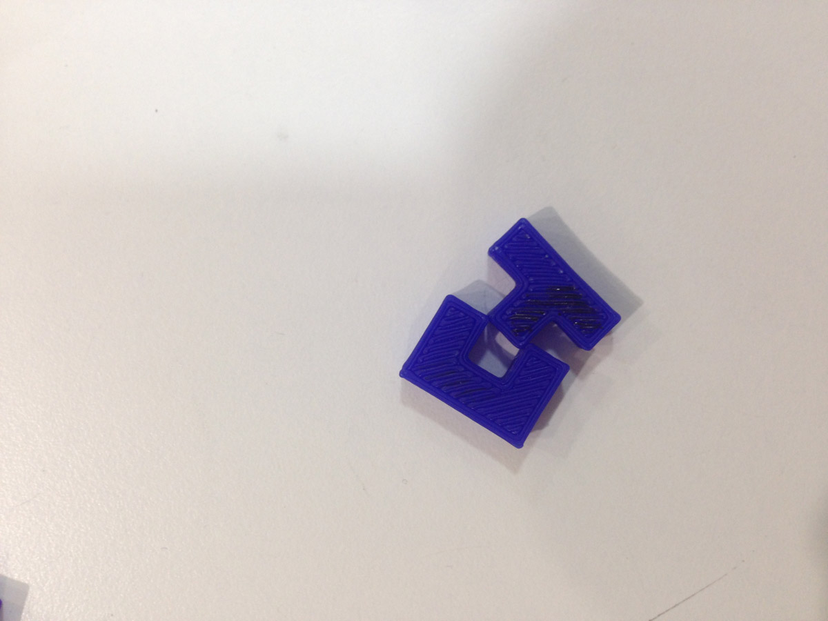
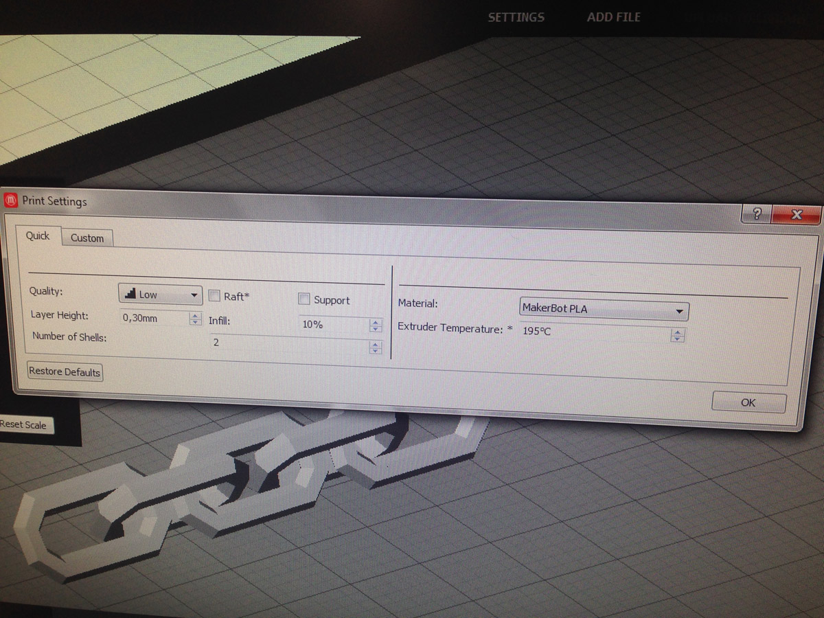
For this I wanted to print an interlocking, they are objects that are chained together so that they have to be manufactured one inside another.
As a group we started to do this:
Layer height: 0.30 mm
Number of Shells: 2
Extrude Temperature: 195?C
Infill: 10%
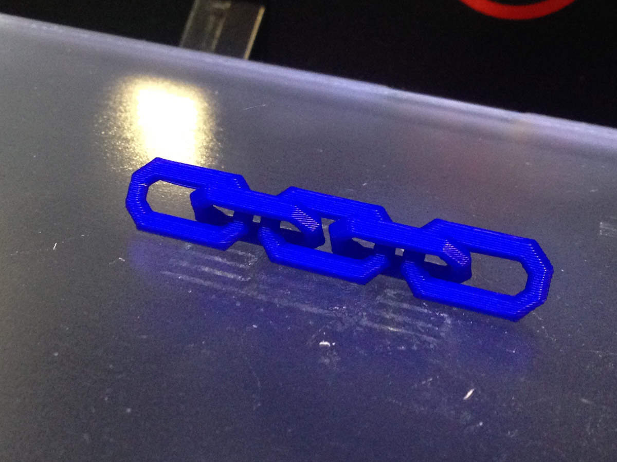
A chain, which rests on a flat side.
I was surprised by his resistance
I made these two objects myself.
3D scan an object (and optionally print it) (extra credit: make your own scanner)
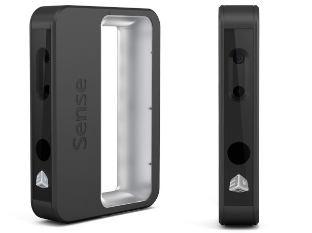 This is the scanner, 3D Systems Sense Scanner $399 USD
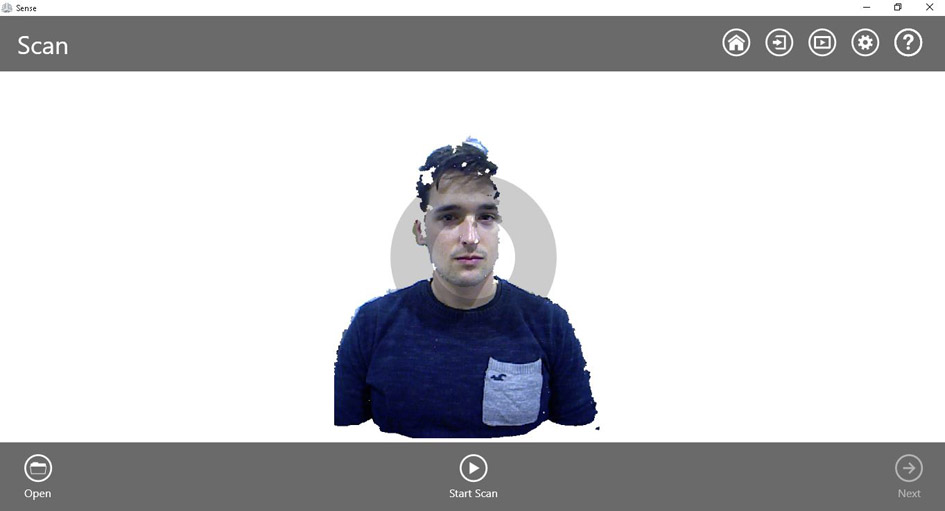
We have done it with the 3d Sense scanner, installed the program that comes with the scanner and we started to scan my head.
This is the scanner, 3D Systems Sense Scanner $399 USD
We have done it with the 3d Sense scanner, installed the program that comes with the scanner and we started to scan my head.The scanner is quite intuitive although it is easily lost in environments with the light in which we did the scanning.
I scanned Juan and Juan scanned me.
 The software its very simple, choose a person or an object,get in and start moving around slowly
To correctly scan a head you have to move around it, slowly keeping a margin of safety, try to make the background differences so that the scanner makes better tracking.
The software its very simple, choose a person or an object,get in and start moving around slowly
To correctly scan a head you have to move around it, slowly keeping a margin of safety, try to make the background differences so that the scanner makes better tracking.
I have few images of the scanning process since I could not make screenshots while scanning, this video shows the scanning process and the techniques for not losing the tracking.
This is me, when Juan my partner, scanned me.
 When Juan scanned me
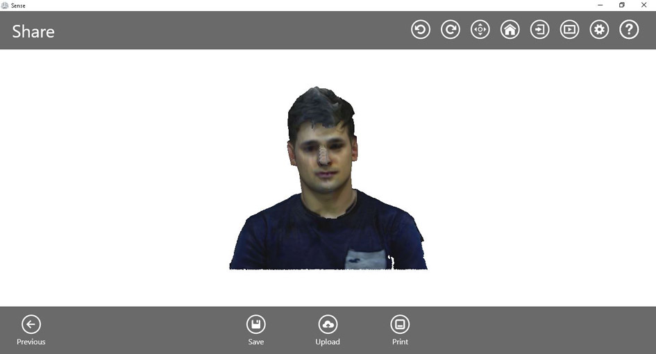 The editor's tools, you can adjust the mesh cut and export the model.
In this youtube video the autor explains the complete process.
The editor's tools, you can adjust the mesh cut and export the model.
In this youtube video the autor explains the complete process.
--- This is the result ---, I made a mesh, the program has a function that is to solidify that it closes the free holes and creates a ready base to print, and also some function of texture retouching, the result is quite well.
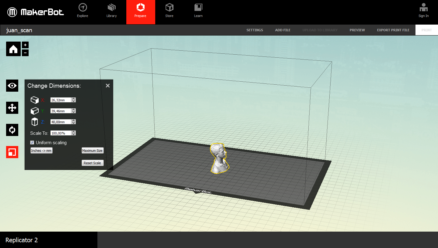 Introducing Juan in Makerbot.
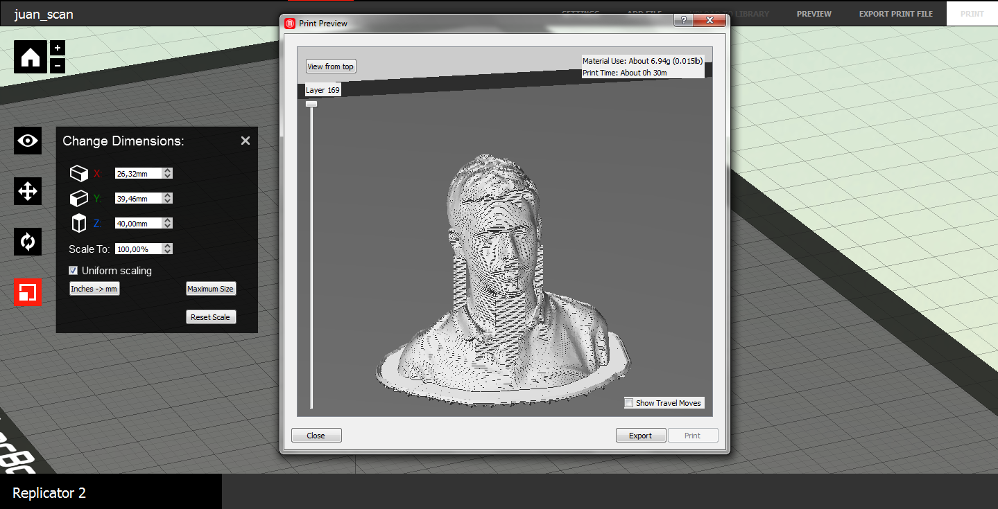 Times.
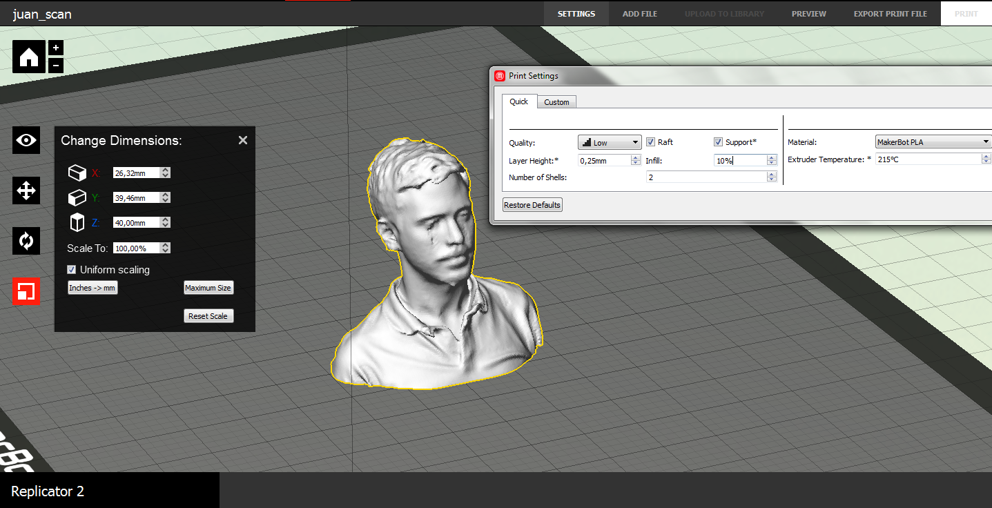 Parameters
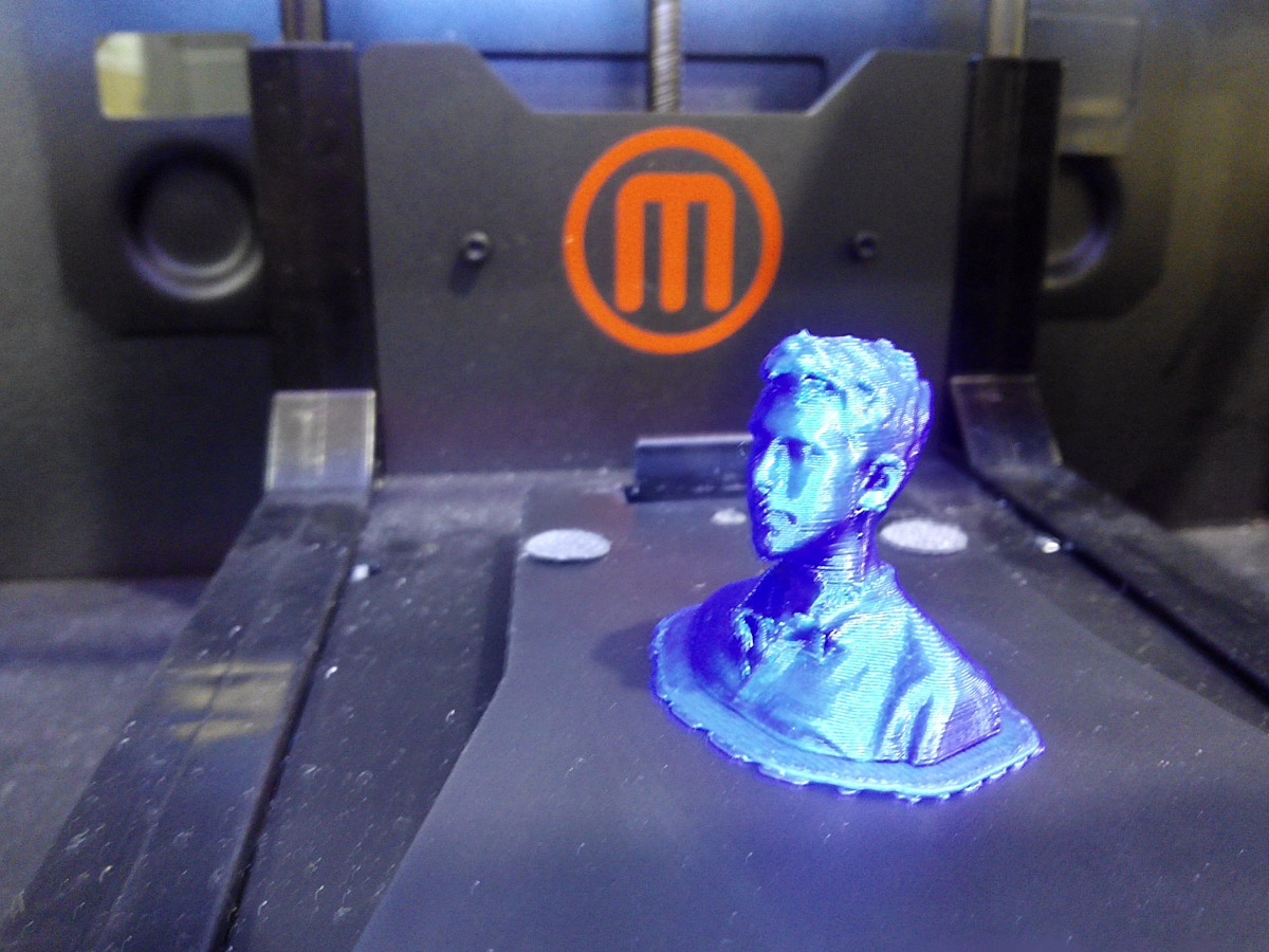 The final head.
4. Making pieces of my final project:
For my final project, which is a rampart anti-terrorist bollard, I wanted to try out a 3D prototype design and print it out.
In designing it I have taken into account minimum tolerances and this object also complies that it is an object that can not be designed subtractively.
I started by creating a sketch in Rhinoceros in 2D
I started designing it in 3D and started by the axis of the ramp that turns on itself,
I finished designing the volumes I had left and making the base that simulates the ground plane.
When I had it, I checked with the tool to rotate that the piece could turn on the other to the desired position.
Problems:
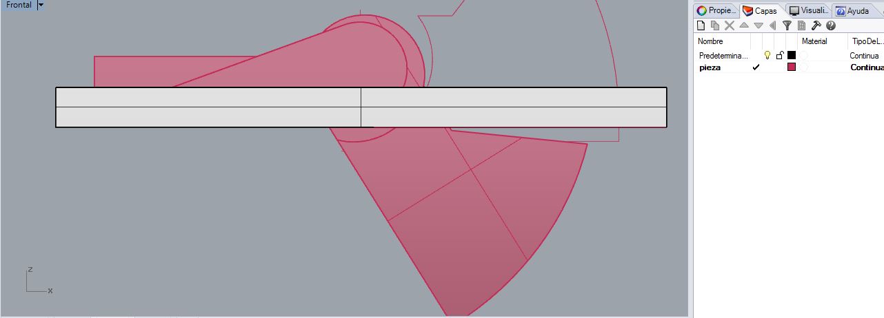
It was difficult to adjust the design so that a piece made of hinge and when the ramp was in rest position there was not a large gap between the 2 parts.
 From 2D to 3D, distance between axis.
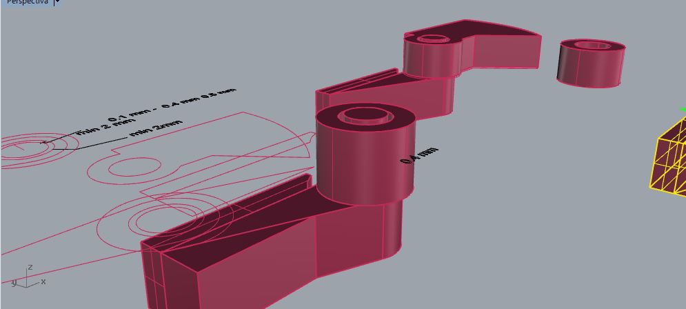 making base parts.
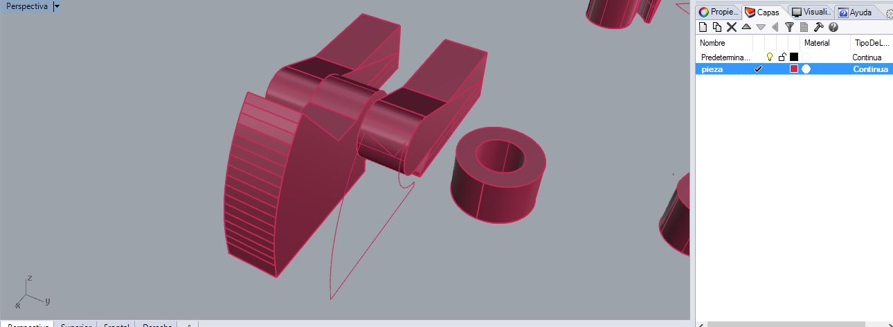 Making the pieces of the ramp by extruding an outline.
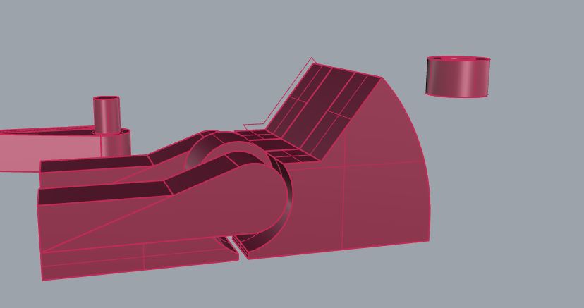
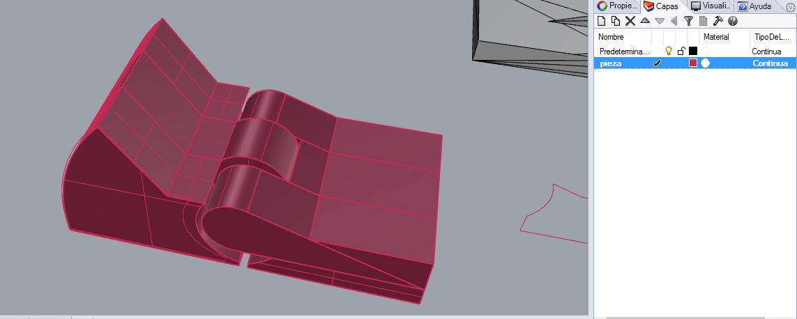
 Checking the rotation of one piece around another
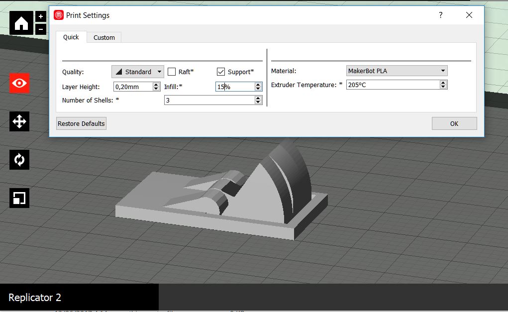 Settings and parametres in Makerbot.
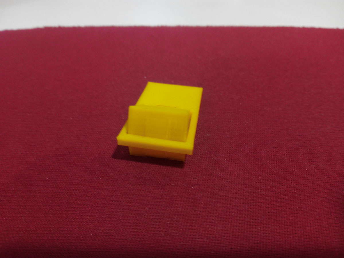 this is a prototype1, Very weak but works as hinge.
This is an object that can not be done subtractively, the reason is that it is an interlocking, it has one piece inside another that can not be pulled the axis of a tour inside the other.
Therefore it can not be done subtractively, to make it would have to resort to making the pieces separately, cut and then welding to obtain the interlocking.
Only with additive fabrication.
Files:
-Base with cones_thing
-Base with cones_stl
-Raccoon with washer
-3D printer tolerance test
-Tolerance hooks
-3D model Juan's head.
-proto 1 "weak"
-proto 2