Mechanical Design, Machine Design
MECHANICAL DESIGN (week 1 of 2)
Make a machine, including the end effector, build the passive parts and operate it manually.
MACHINE DESIGN (week 2 of 2)
Automate your machine. Document the group project and your individual contribution.
Learning outcomes:
- Work and communicate effectively in a team and independently
- Design, plan and build a system
- Analyse and solve technical problems
- Recognise opportunities for improvements in the design
Have you:
Mechanical Design
Our three-person team decided that we would build a candle-making machine. At the onset, we each knew how to make candles in the traditional way: dip a wick in molten wax 20-30 times and allow it to cool intermittently. One member of our team even had recent experience with this method. Candle-making seemed like it could be an easily achieved goal. Little did we know it would lead to such consternation…
First off, I was out of the country. I had planned this trip over two years ago. I was all set to chaperone 15 students in Costa Rica with two Spanish teachers. (My role would be to discuss the science topics while we were there.) This meant that I had to work remotely, and really didn’t get to have an face-to-face discussion time with my colleagues before I left. In-fact, I downloaded and installed SOLIDWORKS only the night before the trip, since that is what my colleagues use. Until this point I hadn’t even touched that design software. I was about to learn it on a plane.

The plan was that I would take some of the design files from the previous year at Lorain County Community College, and use those as a starting point to design a candle-making machine. I wasn’t sure how that would go, nor how the files looked. I was surprised to find the previous year’s files were more-or-less representative, rather than accurate. The assemblies that I had downloaded from the 2016 LCCC page could certainly inform the idea of a machine, but would not be able to be used to inform any of the computer controlled cutting needed for building the machine. I wasn’t expecting Nadya’s Rhino files (I knew we weren’t touching that software) but was surprised at the ‘fuzzy’ accuracy of the files my peers directed me to use.
I set to work learning SOLIDWORKS and working with the design files on a flight from Houston to San Jose. I was able to make a fair amount of progress over the three hours in the air, since SOLIDWORKS is similar to Autodesk’s Inventor (which I had been using). While in the air, I decided on a pulley-based design that used two linear stages from the MtM machine system. It took me several days to finalize this one design, partially because I was making it up in a new software and partially because I spent nearly all of my hours chaperoning students in a foreign country.
The last night before I had agreed to deliver the design files to my colleagues, I decided I should have more than one layout for the machine. Additionally, I had received an email from my local instructor suggesting I should avoid any design that included a pulley from McMaster-Carr. After having worked in SOLIDWORKS for several days, I quickly put together another assembly that did not require a pulley to raise and lower the candles from two linear axis. Instead, the entire stage that held the candle moved it laterally would be moved up and down by other stages.


Wednesday morning in Costa Rica I had submitted two designs to my team and connected to the lecture on my Google Fi cell phone, which (thankfully) has a fantastic international coverage plan. This basically concluded my work while in Costa Rica, since it was also my spring break and we were entering the mountain and beach days of the trip. It felt like an appropriate time to get away.


I returned to Cleveland and in less than 12 hours was meeting with Paul O’Neil, who had a wealth of information for me. We talked over the design choices they had made in my absence, and looked at the cardboard stage that Marty had built. In our meeting at Think[box] Paul suggested a few revisions to our machine that would simplify the designs even further. We decided it would be best to move a rotary stage along an elevated linear stage in order to achieve our goal. Paul also had the heating bath for our wax. This meant another redesign. Finally, once I got my hands on the cardboard stage Marty had assembled, it was clear he had some difficulty. The moving parts were particularly hard to move – it didn’t take long until I had just disassembled the thing. I would be designing this machine with specific and cut-able designs, from the ground up.


Building from scratch turned out to be much simpler. Furthermore, with all of the ‘fixed parts’ in hand (such as motors, bushings, and aluminum rods) I was able to make accurate and parametric designs. I decided to build the entire assembly in SOLIDWORKS again, because my colleagues still preferred it as a design medium. Once a design had emerged, I began to think about the materials. The main body could be cut on the ShopBot from leftover plywood from my ‘Make Something Big’ week. The moveable assembly would be laser cut from some 1/8 inch plywood I had from a previous endeavor. While the body would be press fit, the moving stage would be more of a ‘press alignment’ with screws to hold it in place. I could make the walls with the bushings three layers thick and glue them together like pieces of custom plywood. Ideas were starting to become concrete, and I was able to design with the materials in mind. The last piece that needed modification was the depth of the moving box. I ordered a geared stepper motor, but was unsure of the depth until it arrived. Once I could measure this distance with calipers, I adjusted my design and got to cutting and assembly of the machine. It turned out much nicer than any cardboard stage ever would have. The parts came together without and terrible difficulty and everything moved as it should, with only minimal effort t if unpowered. I am sure that it is perhaps the entire machine is too sturdy, but most of the wood was scrap in the lab anyway and it cannot hurt for a prototype.

Machine Design
Getting the machine to work is a whole other endeavor. Nadya Peek certainly developed something special with her MtM machines, and they are delightfully easy to modify and expand (for the initiated) but can still serve as a significant barrier to someone being introduced to the medium.


There are several hurdles to cross to get an idea to turn into a reality. Within our LCCC group we tried three different operating systems (which included running Ubuntu off a USB drive on my laptop). We also looked at two different Python versions, a few iterations of the pygestalt software, and several iterations of the RS485 connector. We even struggled with the persistence file, and how that affected our machine and Gestalt boards. One of our strengths as a group was our ability to work flexibly in different locations, but it often meant we did so without the direct assistance of our local instructor.


The simple part was deciding on the general plan of what the machine should do. Dip a wick in molten wax and wait before it does that same task again. Repeat about thirty times… making this happen started with figuring out how to install the software that we would need. Then we would need to figure out how to connect to the Gestalt boards and finally manipulate the machine’s code until it did what we wanted. Since this was unbelievably complex, I will summarize that work here step-by-step so that future generations can follow along. These instructions will not include an integration into Fab Mods, but will cover how to build software for command-line operation of the machine with the use of a csv file for informing the machine’s motion. I installed this toolchain on a USB verion of linux first, on later to realize that the USB Ubuntu I was using did not have full use of my other USB ports, so I could not get the machine to work from there. Therefore, I worked on the Windows 10 computer I have used for the rest of Fab Academy, so these instructions will fit with that operating system.


How to make the MtM machines go: Zero to Functional
- Install Python 2.7.xx
- There is probably a different sub-version of python 2.7 out by now. I used 2.7.13 as it was the current at the time. Do not install Python 3.x – this is not the same thing!
- Get and Install pySerial
- The good people who developed pySerial have also built their own python-based installer into the package, so that makes it fairly easy to do this bit…
- First, I made a folder called ‘Python Expansions’ in my documents folder, since I knew I would be installing a couple expansions for this project. I downloaded the pySerial zip file and extracted it into the ‘Python Extensions’ folder.
- I then ran the pySerial installer mentioned above from the command line. You can probably click on the file and it will work. Instead, I had just come from doing this install in Linux, so I opted for the command prompt option. You can open a command prompt and cd your way to the file location, or you can hold shift and right-click in the window to open a command prompt window directly to that location. Then you just run the python script with the command: python setup.py install This will be the same for many python expansions that include a python-based installer. It is nearly as nice as if the expansion’s authors built a proper Microsoft msi installer.
- Get and install Nadya Peek’s pyGestalt library from GitHub
- This repository is linked to all over the place in Fab Academy. Get to the GitHub repository and use the download zip button to claim your copy of the repository.
- I extracted the files into my ‘Python Expansions’ folder again and then installed the Gestalt system. See the instructions above for how to install a python package with a setup.py file included.
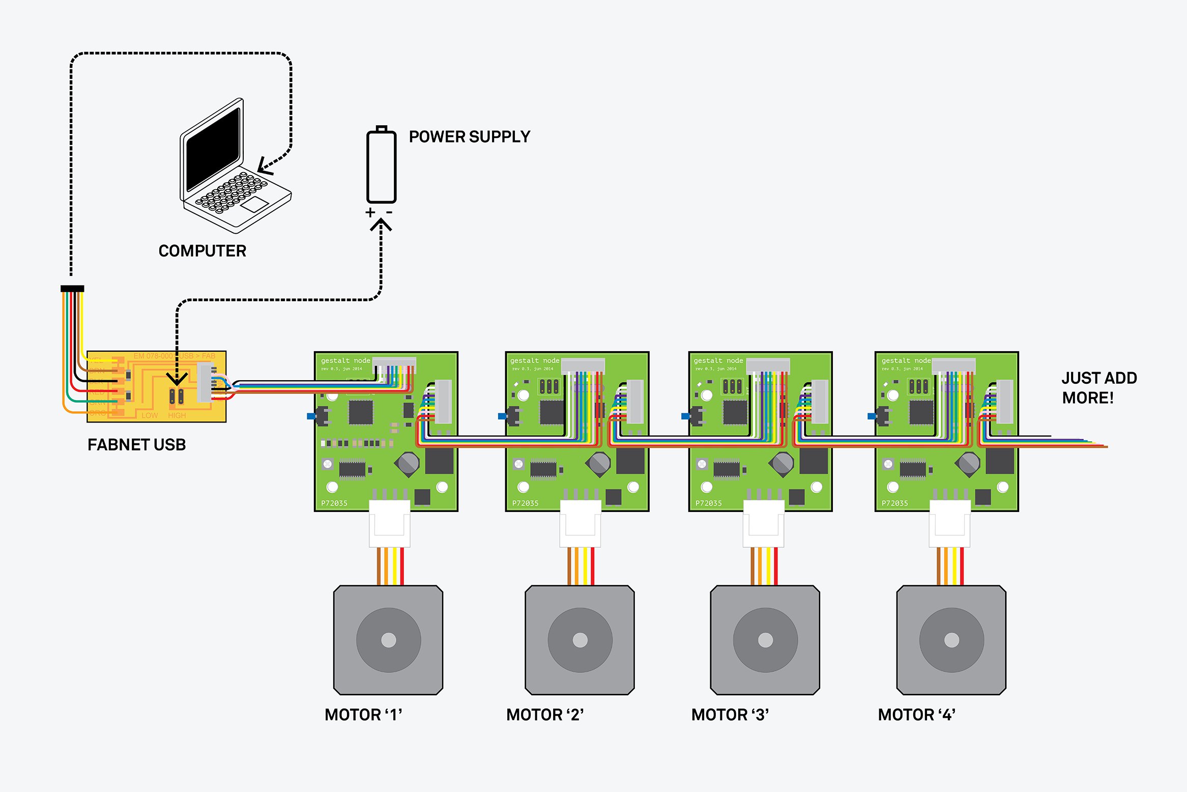
- Hook up the FabNet board [one of my colleagues had built it]
- This feels like it should be ‘Plug and Play’ but it is so much more than that…
- First off, make sure that the board was assembled properly – you don’t want this cable to be screwed up, as you are plugging it into a computer you likely know and love. I have run 12V into a USB port before. You don’t want to see it happen. At best it forces a reboot, yet it has the potential to brick your machine. Yes, I’ve seen both happen.
- The 12 supply lines need to have a power source that is not your computer. One of my colleagues had a nice benchtop supply – this worked great. If you don’t have one of those expensive pieces of equipment: instead, you could try a properly spec’ed old laptop charger or order a 12V supply from Amazon (make sure it has enough current capacity).
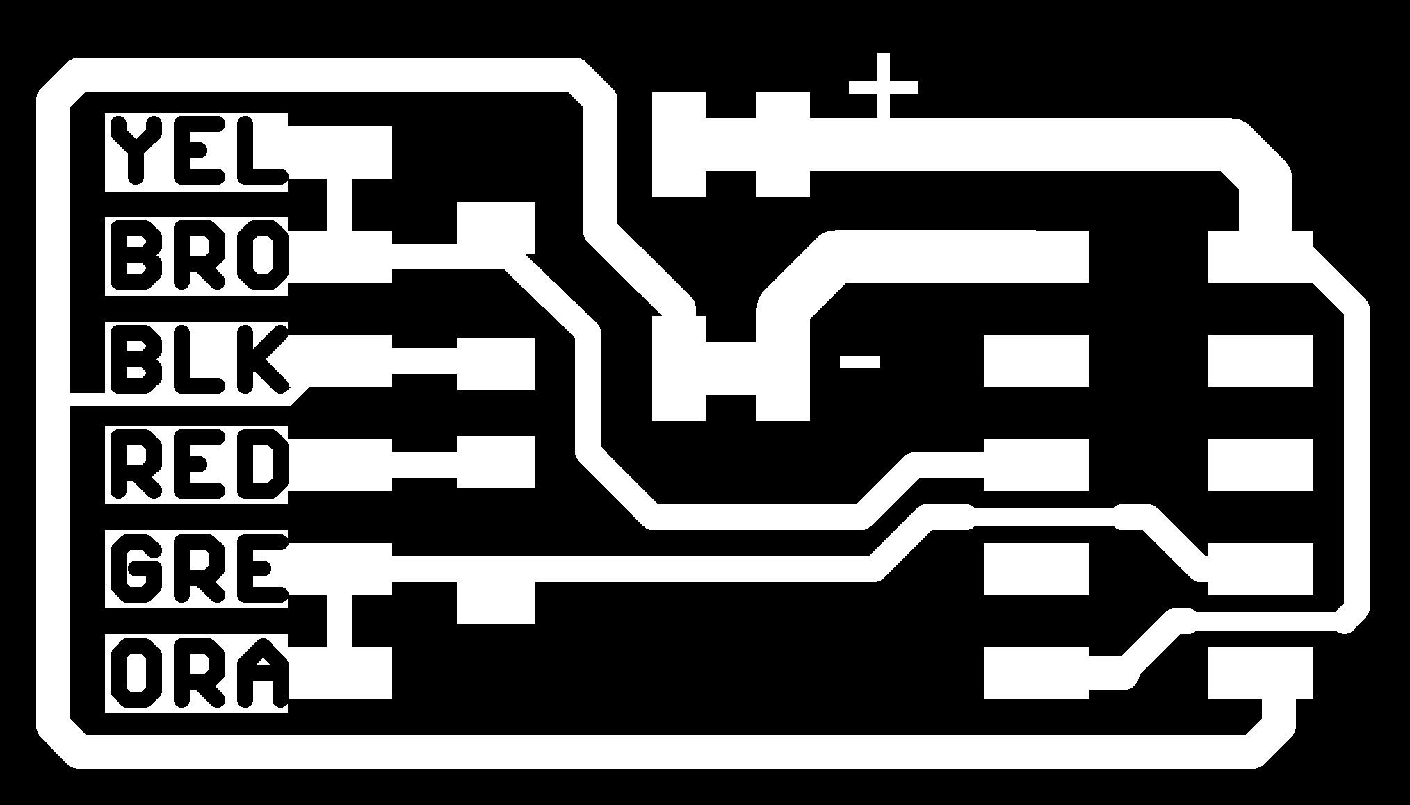
- The last part of the FabNet board is the 10-conductor ribbon cable to connect it to the Gestalt boards. This can be messy or clean. There are two versions of the FabNet floating around the Fab Academy pages: Version 1 and Version 2. If you have version 1, you will need to hack apart your ribbon cable and make a janky-looking connector to interface with the Gestalt framework. If you use version 2, you can have a nice, clean ribbon cable that is interchangeable with all of the others. I will encourage you to think about this before you implement your FabNet board. Maybe you should stop and build the version 2 board right now…
- Hook-up the Gestalt Boards (just talking about the wiring)
- The wiring on the Gestalt boards is not hard; you just need to be careful to get it right. In addition, one of the MtM machine pages explicitly discourages you from ‘hot plugging’ the cables, so make sure you power supply is not connected and no code is running when you move plugs around on these things.
- The designers of the 10-pin connections on the Gestalt boards had good sense. They designed it so that the 12V and GND pins are flipped on the two ends. It means that if you plug the ribbon cable in backwards you should not fry anything. Only that your communication will not work. **If I had one thing to recommend, it would be to redesign the Gestalt boards for polarized connectors with strain relief, such as these and these from DigiKey so you wouldn’t plug it in backwards. The same idea can be applied to the FabNet boards…
- Get the Gestalt boards going with the example programs included within pyGestalt
- The most useful example programs are all inside of this file location: …\pygestalt\examples\machines\htmaa\ (Keep in mind the things preceding the file location I am showing may be different depending on where you put the pyGestalt folder in your machine.)
- You are about to start with single_node.py but you aren’t quite ready yet to rock and roll. First you need to double check a few things:
- Have you attached the FabNet cable to your Gestalt node and your computer properly? Check the diagram here to see if it is correct…
- Did your Gestalt Nodes ever get programed? If you are working in a Fab Lab that is not new to Fab Academy, then the answer is probably yes (and you should move on). If you are working with unused Gestalt nodes, you should talk to your instructor or follow the instructions about halfway down this page.
- Is there really voltage being delivered to the Gestalt nodes? This is best checked with a multimeter on the voltage regulator chip. The voltage regulator is the large three – pronged IC, with a heat sync to the board.
- This is a Windows 10 Tutorial, so we will need to make the appropriate OS changes, but luckily, they are not too bad…
- First is to figure out which COM port your Fabnet board is plugged into. This is easiest to do by unplugging all other USB devices and checking Device Manager. (Press the start button and type ‘device manager’ into the search panel to quickly access the program.) The screen should look like this, and the if you click on the COM ports chevron, you will see the com port of your FabNet board, and hopefully nothing else.
- Open the single_node.py program into the Python IDLE (right click on the file and choose this option)
- Start reading the code and look for the text that says: portName = '/dev/ttyUSB0' (It should be way off to the right, somewhat near the top of the document.) This is the location of the FabNet board when plugged into a Linux computer. You will be changing this code.
- Replace '/dev/ttyUSB0' with the text: 'COM7' (only that you should use the number of your COM port instead of the 7 shown here – it was COM7 for me).
- Save this altered file with a new name, so you can have it and keep the original too. I used the name: single_node_win.py
- Run your new single_node_win.py file in the Python IDLE so that you can see all of the printed messages (or error messages) more clearly. F5 is the shortcut for this in IDLE.
- Hopefully everything worked and there was a line that asked you to identify the node. When you see this message: press the button on the node, and hopefully something moves!
- If you are having connection problems, try these:
- If your FabNet board is not connecting, try unplugging and plugging it back in. This is common.
- Make sure your Gestalt nodes are powered.
- So you’ve gotten the first Gestalt node to move once (or more), but you want to try the next one and it will not work… here is why and how to fix it
- Remember that the second time you excitedly ran single_node_win.py and it worked so well? You may not have even noticed that you didn’t have to identify the node again, considering all of your giddy excitement. This is because of a persistence file that the code generated to remember the node. If you want to use a different node, or your setup changes too much, you will likely need to trash that persistence file so that the code can auto-generate a new one.
- If you need to clear out the persistence file, look around in the same folder as single_node_win.py for a file called: test.vmp This is your persistence file. Delete it.
- Now any other Gestalt node should be useable with single_node_win.py again, but you will need to identify the new node and a new persistence file will be generated. From this point on you can keep this generate / delete cycle going to calibrate the system to any new nodes you want to add or swap out.
- Move on to bigger and better things.
- There are many example programs In the htmaa folder to explore. Read their code to see how many and what types of axes they involve. One will likely be close enough to your goal that you can modify it later. Adding a second or more nodes is relatively easy, provided you get the wiring right and remember to remove your persistence files before changes. This is the real magic of the Gestalt system: object oriented, extensible machine building.
- Alter the code of one of those examples to fit your needs
- Way at the bottom of the example python programs, there is a section labeled:
#------IF RUN DIRECTLY FROM TERMINAL------ - Starting at this point is the procedural code that you need to run the machine. Just run it from the IDLE terminal, as you did before. This method worked for me and was delightful.
- Sure you can do other fancy things with wxPython based GUIs and web interfaces, but that is too rich for my blood in this particular instance. Pursue it if you wish, but our team was small and none of us were developers in a past life. (Also, wxPython seemed to be having trouble in April 2017.)
- Altering this last section of the example programs is what you will need to get the machine you built to act the way you want. Play around with this and try to get Python to do what you want. I suggest many print messages for debugging. Finally, there is a whole Gestalt Documentation available online that could be useful… Good luck - I hope this instruction set was helpful!


You can see all images (used and unused) from this week's work HERE.