
In a group, we were to make a machine, including the end effector, build the passive parts and operate it manually. We needed to document the group project and automate our machine.
The learning outcomes expected for this project were:
We are extremely lucky to have a very talented team of four members completing the FabAcademy program. Each member has years of experience in different areas that are extremely relevant to the FabAcademy curriculum. Each member has different strengths that make our group extremely collaborative with years of knowledge.
The Team Members Are:
The project started to be planned on the first day of class in January. Scott, our FabAcademy guide, mentioned to us that we should start thinking about our Group Project among the various other aspects of our FabAcademy curriculum. It seemed awhile before our group project, but it was discussed on and off. We formally started to discuss Gestalt and modular machines that make the week before our session on March 16th. Chris and Scott took out the motors, Gestalt board, and materials to start the idea process. We discussed before class some ideas. They ranged from foam cutters, to lathes and machines that drew. We had many ideas and it started the process of narrowing down what could be done and the programming behind each idea.
After our week long break, we reconvened and met as a group before class with all the parts of the modular machines that make as listed on the FabAcademy BOM for the project. We started by looking at the examples posted on the FabAcademy assignment page and past group projects to see what has already been attempted.
We also looked at the LCCC FabAcademy 2015 group project. The LCCC Fab Lab still has the old zen garden around so we brought it in the lab and looked at the issues they confronted and retrofitting they attempted to complete the job. This was instructive as we saw how they build the cardboard boxes with smaller laser's and how they automated the project to work. Nadya even mentioned this project in her Recitation on Machines That Make.
As we seriously discussed the project, many ideas were considered. As a group, we thought the foam hot wire cutter was exceptional and seriously considered heading in that direction. We then decided to think about how many axis we wanted in the project. It started at two and ballooned to four. We decided to look at machines that could draw and this was another direction we wanted to head. Some wanted to make a lathe like some groups completed before. We could not find the project we could agree upon until we discussed playing music. We ultimately decided on making a machine that would play chimes. The decision was decided upon by the group as a new and unique project that we could not find any similar to ours. We had a direction and now it was time to come up with a design.
We talked about the design as a group. Tasks were assigned based upon strengths. Karen would draft the design in Solidworks. Tim would produce the wood structure. Chris would take charge of the Gestalt boards and programming. Matt would be in charge of making the cardboard boxes. Karen was tasked with creating the windchimes. Matt would create the final group project page. We all felt comfortable with the assignments and headed off to create a machine that would play the chimes.
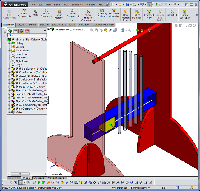
The design phase was worked on by the group. Karen created the drawings in Solidworks of the project. She created our intial drawings that guided us along the way. Chris then created a 3D model on SketchFab to illustrate what the project would look like in 3D.
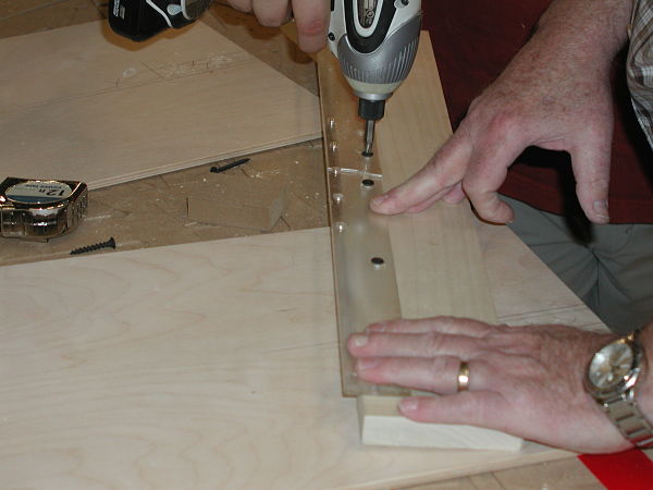
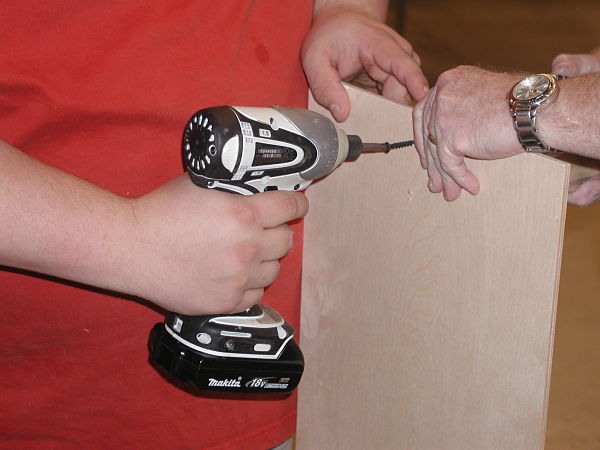
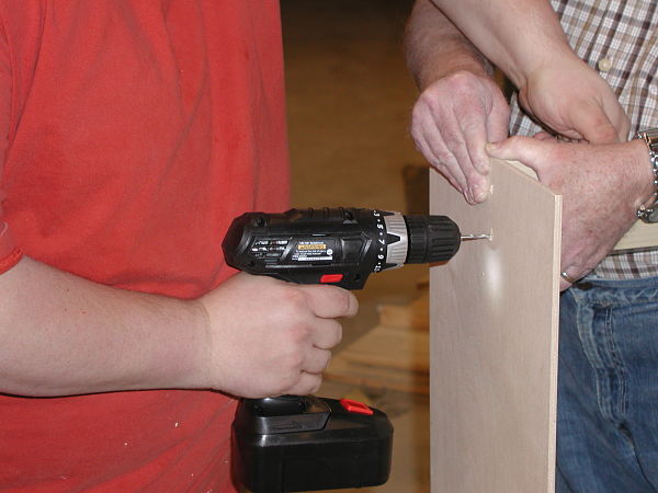
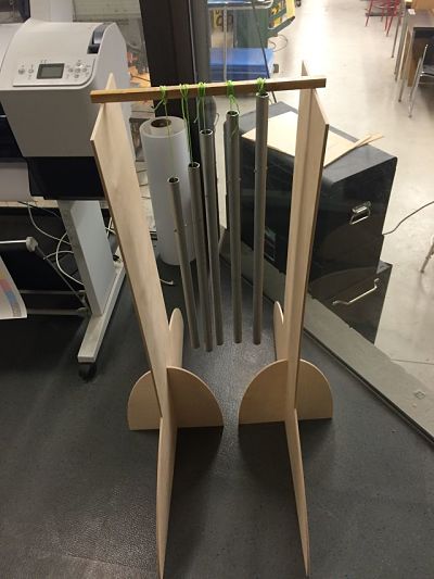
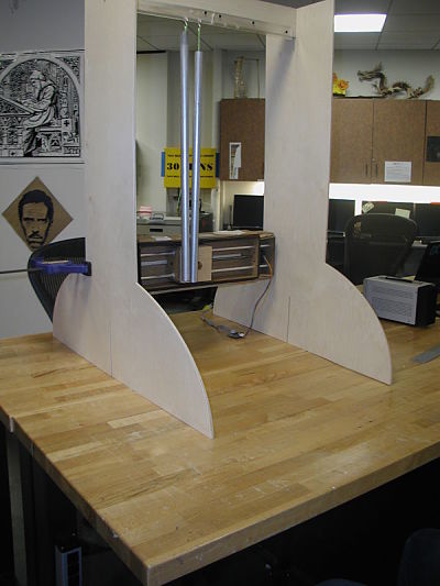
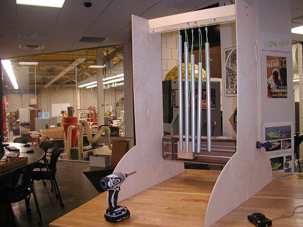
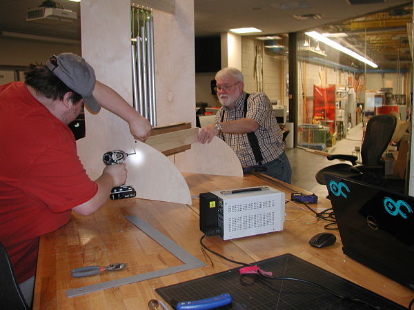
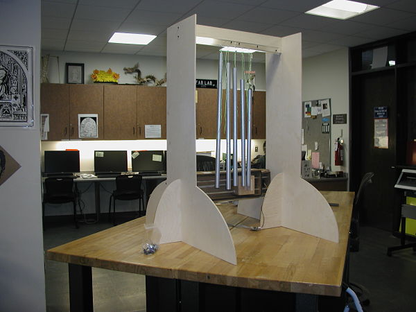
Tim created the frame for the chimes to hang on. He used the dimensions from the drawing and manufactured a sturdy wooden frame to hold the chimes. Karen then created the chimes and they assembled the initial frame and chimes.
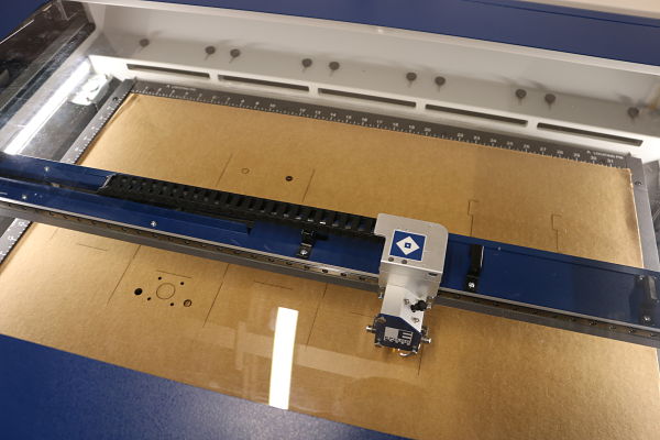
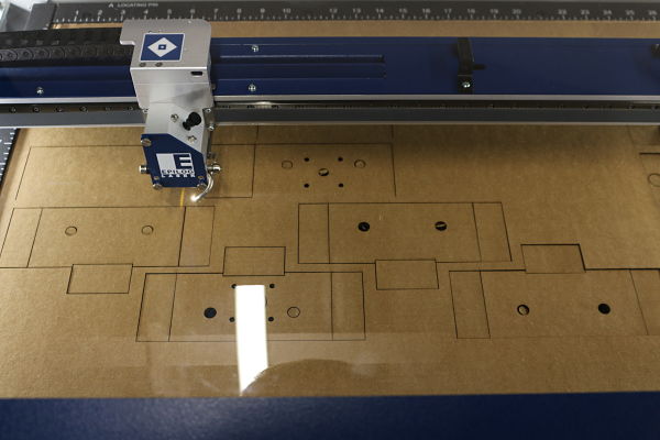
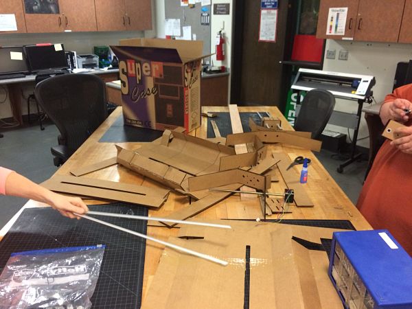
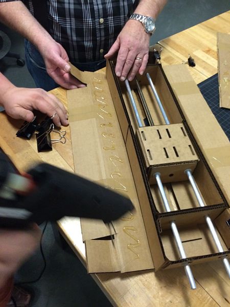
Matt was tasked with creating the cardboard boxes that would work between the stand and the chimes. His responsibility was was to cut out the boxes to be used to house the stepper motor and guides. The laser he used was the Epilog Fusion M2 32 with 50 Watts CO2 laser. He approached the project by cutting it using the directions for ULINE and the smaller laser. He downloaded the text cutfile and compiled it in CorelDraw to create the .dxf file. He needed to cut the box in several layouts to create the box in parts. He used the Color Mapping process to vector cut through the blue lines (S24/P100/F100) and only perferated the red lines (S68/P70/F100). These results were obtained after much trial and error using test cuts on cardboard. The first two cuts were too strong and instead of perferation, cut through the cardboard.
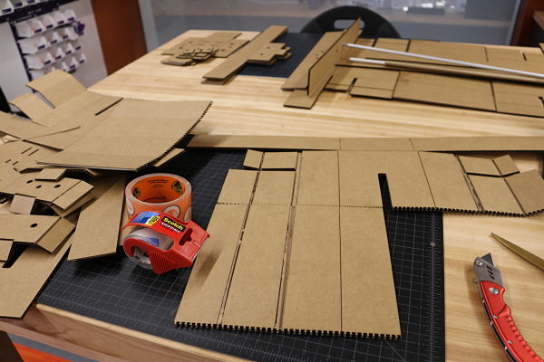
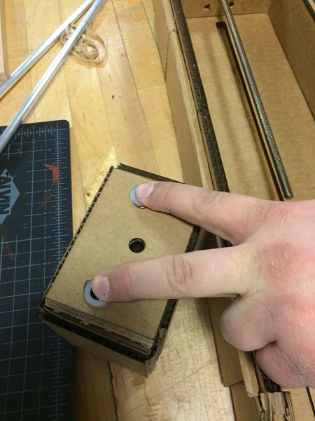
Matt then had to assemble the boxes. He watched the animated .gifs posted on the FabAcademy pages, but when he went to fold and assemble the boxes, he needed to retrofit the boxes to work. The thickness of the cardboard produced much added sizing. He cut off one of the side flaps on each side and it seemed to work better. As a group we almost made the boxes out of wood because we became frustrated with the thickness of the boxes. We decided to eliminate some of the ends to free up size. Matt noticed in the downloaded files, it lacked end holes so he had to cut holes to allow the rods to protrude through the end of the box to accomodate the length of the guide rails. We used hot glue and binder clips to act as clamps when applying the glue. We even added superglue to the plastic rings holding the guide rails in place. Matt was helped by Tim, Karen and Chris in assembling the boxes.
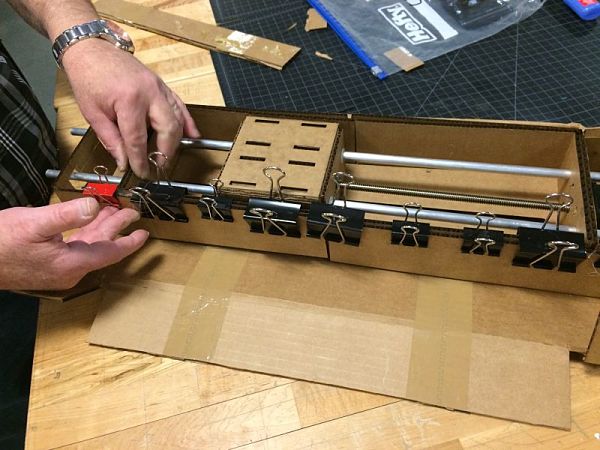
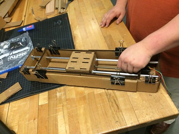
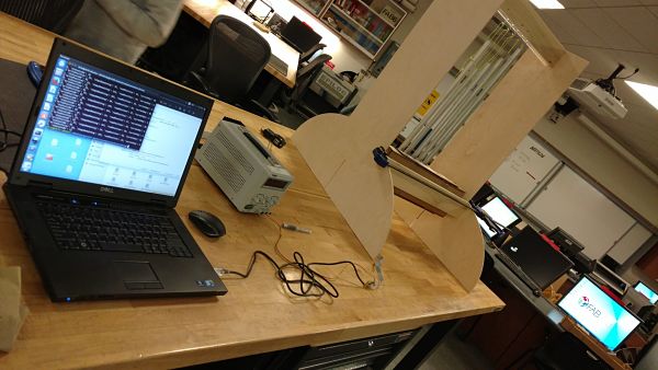
After the boxes were assembled, we took the box over and assembled the Gastalt board. Chris had programmed the board and after we installed the carriage in the boxes we wanted to see if they did indeed work. Chris programmed the first box to see if everything worked correctly. Below is the video of our first test.
We then wanted to test both boards hooked up to two axis to see if we could program them correctly. This was set up by Chris and we had a successful test as illustrated by the video.
The group worked to assemble the pieces together. The wood structure and chimes needed to be assembled with the cardboard carriage and effector. This process took awhile to get everything lined up correctly and trying the various effectors.

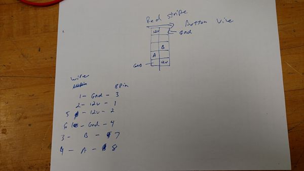
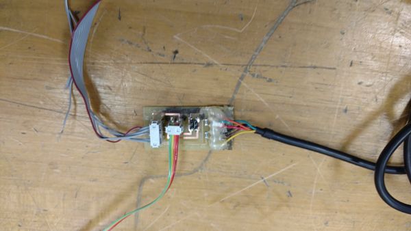
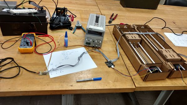
To make the fabnet board Chris used the Eagle files and exported the layout as a Gerber file for my LPFK S63 rapid prototype machine. After cutting the board out he soldered the supplied RS485 cable and resistors to the board. Chris also soldered 4 and 8 pin headers for cable hook ups. The hardest part of making the Fabnet board was creating the cable to interface with the Gastalt boards. To make sure he had the right pin-outs he used the documentation from Nadya and a multimeter on the old cable to make a pin out. After that Chris stated to make the cable and when he was done he tested and it worked. To make sure the Fabnet board will hold up a little bit better he used some hot glue on the RS485 wires and the 8 pin header to increase the strength.
The first item Chris had to do was install the Pygestalt framework. He cloned the library and then ran sudo python steup.py install.
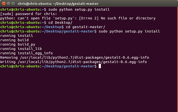
The next item was to find and run an example to make sure the Fabnet and the Gestalt board are working. Chris found the simple single x axis example and ran it from the command line.
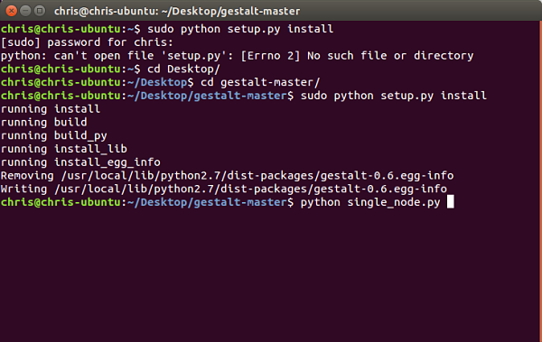
After a simple a simple test he decided to hook up two axis and try the x-y plotter code.
Once he knew that it worked he read through the code and started to change the speed with stage.xNode.setVelocityRequest(12) line to see how fast he could get the stepper motors to run. This was about 16 in that function before it was too fast and started to skip. After playing with the speed Chris chaged the code to find the max limits of travel and how to add more paths to the code. For the final code we used the single node code that imported a csv file that has some random moves to make the chimes seem more natural. We also found out the initial speed of 16 was too fast and we slowed it down to 12 and the chimes sounded and ran better.
We next needed to assemble the machine to actually perform the action of playing the chimes. This needed an effector to make contact with the chimes. Several different versions of effectors were tried. As you can see in the video clips, a solid wood pieces was used. A ball was placed on the end in another video. Several tests were conducted to see which effector worked the best.
These are the two approaches using the wood effector
This is using the ball effector
We had to solve a few technical problems as mentioned along the way. We needed to choose an effector that best worked for the chimes. We also needed to get the programming speed correct so the chimes would play but not bump into each other and create more sound. We had to determine how to position the cardboard box to play the chimes. We also had much debate about how many axis we needed to get our machine to do the correct functions. For example, would two axis provide anything more than a single axis? These were the technical problems we faced along the way.
The oppportunities for improvements in this project were:
Project Files: