Week-8: Embedded Programming
The 8th assignment in the Fab Lab was to do the following and report every step taken during the process.
Learning outcome
1) Identify relevant information in a micro controller data sheet
2) Implement programming protocols
Have you:
1) Documented what you learned from reading a micro controller data sheet
2) What questions do you have? What would you like to learn more about?
3) Programmed your board
4) Described the programming process/es you used
5) Included your code
About the ATTiny:
Documented what you learned from reading a micro controller data sheet. I have gone through this file provided in the fab lab website for the Micro-controller with 2K/4K/8K Bytes In System Programmable Flash.
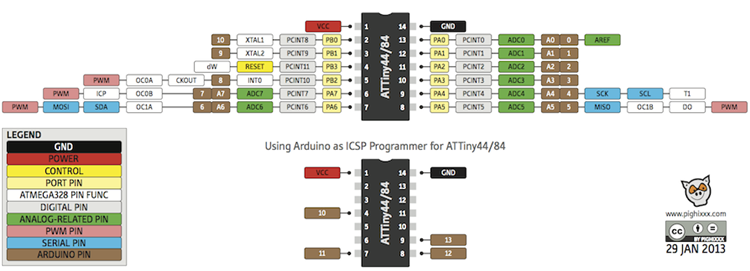
For every product there is a data sheet that provides all the required specification about the product and needed details. for the Attiny, I learned about the pin outs in the Micro Controller, their names and how to use them in connection with the ISP cable in the programing phase.
CLICK HERE . 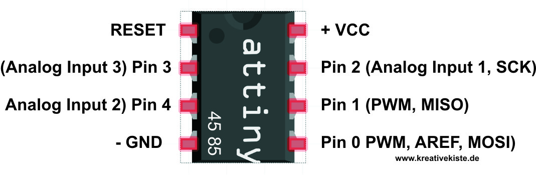
Reading Datasheet
I have been reading about the ATTiny micro-controller sheet in order to figure out how o connect it to my week's assignment. It was not as tough as it seems once I figured out what those meaning are about especially what each Pin is there for. Here is a breakdown of how o read the pins:
- SCK stands for Serial Clock which represents the programming clock
- MOSI stands for Master Out Slave In which represents the line that connects in system program with the programmed device.
- MISO stands for Master In Slave Out which represents the line that connects the programmed device with the in system program.
- RST stands for Reset which represents the task of keeping the targeted AVR active.
- GND stands for Ground which represents the common ground for the whole circuit
Types of Memories
So after knowing what those shortcuts stand for, the micro-controllers include the CPU unit with an input and output memory that is divided into 3 types:
type-1: Flash Memory, which is the memory he memory that stores the set data or the data that do ot require any changes. it is also considered as the program memory once its set.
Type-2: Registers, which are little element in the micro-controller that includes a capacity of 8 bits and can also be accessed by the arithmetic and logic unit of micro-controllers
Type-3: SRAM, which are the memory that used most commonly used in the system in order to allow to store the data that required a repeated read and write
What questions do you have? What would you like to learn more about?
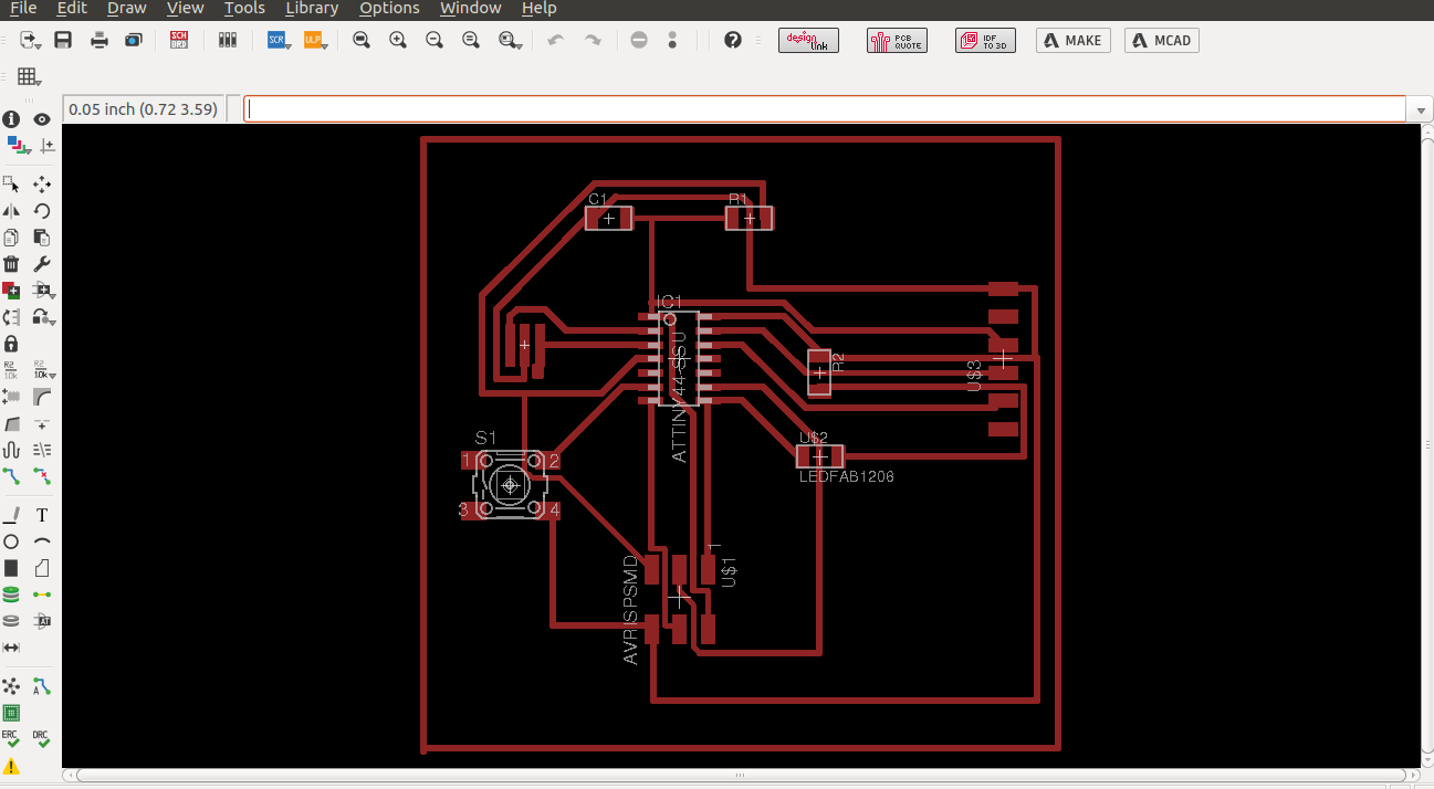
as shown below, the design shows a 100% rerouting but all attempts failed once the milling and soldering is completed. some attempts failed just after the milling process when i checked the sheet for any short circuits. failure occurred from having the channels at .15 mm and i had to increase it to avoid any future failure so i increased it to .18 mm for now.
other mistakes occurred after checking all the milling process and felt confident to carry on with the soldering process, then the soldering was not perfect as well. s i had to repeat this process up to 5 times and still failing. i will update the report as soon as i get a completed attempt t carry on with the programming process.
Hero Shot of the PCB Board
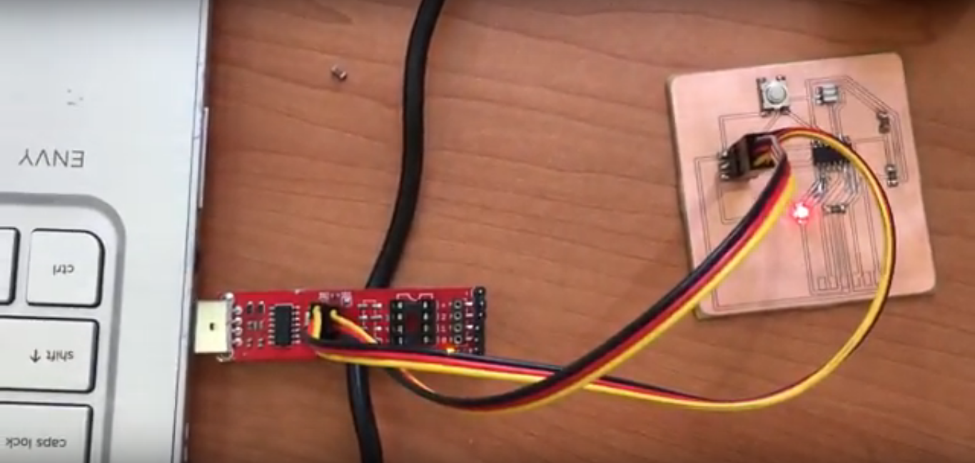
The programing Process
First of all, the same milling and soldering process was used. the process was getting easier as we went from week-4 to week-6 till week-8 now. the more we practice the soldering process, the easier it is to perfect it. the main issue was being very careful in soldering the micro controller to avoid any shortcuts or low connections to other components.
So I have downloaded both softwares to start the programming process. i installed the at-tiny board board support in Aurdino.
the process of the code was defined as describing the number of pins in the beginning. The Zero in the second statement indicates that the button pressing is the initial state of the code. Then defining the input and the output of the LED followed by the state of the button if its high or low. the last IF statement reads as the pressing command vs the blinking command in the board.
About The Code Used
Here is why this code was use:
1) The Pins connectd are 5 and 7 thats why we can see the first 2 lines to represnts which pins we connect to.
2) The 5th pin is connected to the LED as seen in the command ledPin
3) The 7th pin is connected to the Micro controller as seen in the command buttonPin
4) The initial button status was set at ZERO to indicate no action to be taken when the button is not pressed
5) the VOID set up was set to indicate that the output is an LED light and the input is a press button
6) Inside the VOID LOOP, I gave the command of how it should work which is ButtonState command is to state that if the button is pressed, the LED will light and keep on lighting otherwise it will go OFF.
const int ledPin = 5;
int buttonState = 0;
void setup() {
pinMode(ledPin, OUTPUT);
pinMode(buttonPin, INPUT);
}
void loop() {
buttonState = digitalRead(buttonPin);
if (buttonState == HIGH) {
digitalWrite(ledPin, LOW);
} else {
digitalWrite(ledPin, HIGH);
}
}
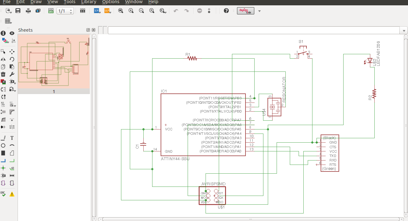
Files Used
Board FileSchematic File