Final Project - SQUAT SOLE

About SQUAT SOLE
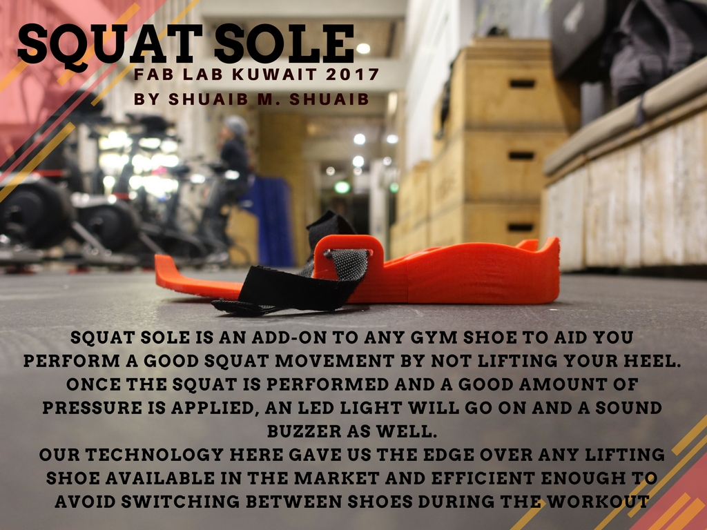
Squat Sole is a state-of-the-art training kit for those who seek injury free work out. as we all know, the foundation of the body is the foot, with every step we take whether in a work out or day to day activities, the correct motion of the human body begins with the how you step on the foot.
I believe such knowledge will require a huge campaign to create awareness of where or how you should step while working out but with the help of the technology these days, we can tackle this issue and solve it easily with the Squat Sole.
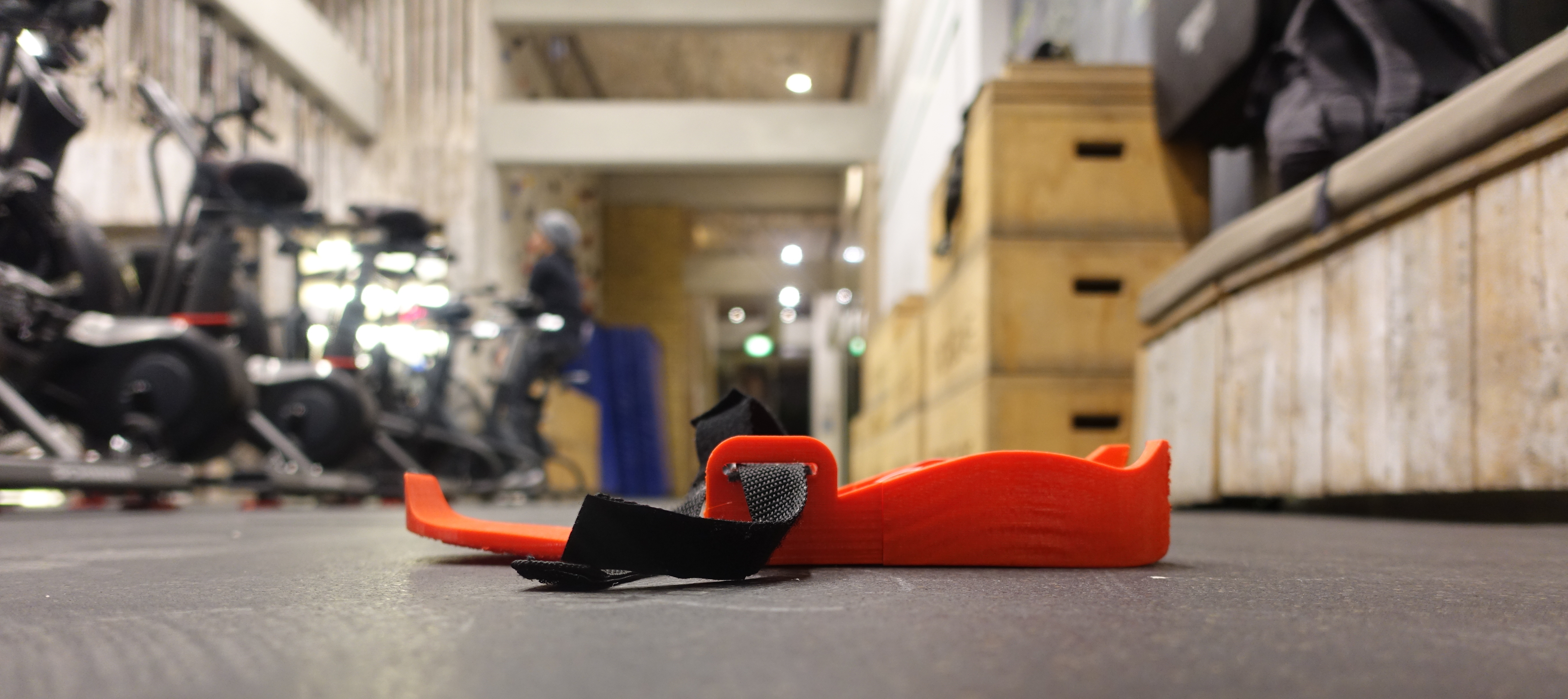
In Squat Sole, we are creating an external shoe sole that you can attach under any gym sneaker and senses where exactly you are stepping on your foot. The concept is very simple, and it could be further developed by connecting the sole through an application that shows the progress of your squat step whether in the middle of the foot , on the toe or at the heal which is the recommended location.
Project Concept
the idea was developed in the early stages of the Fab Lab training period. The concept sketch was developed from existing Squatting Shoes that are available in the market. The picture below shoes where the idea has come from.
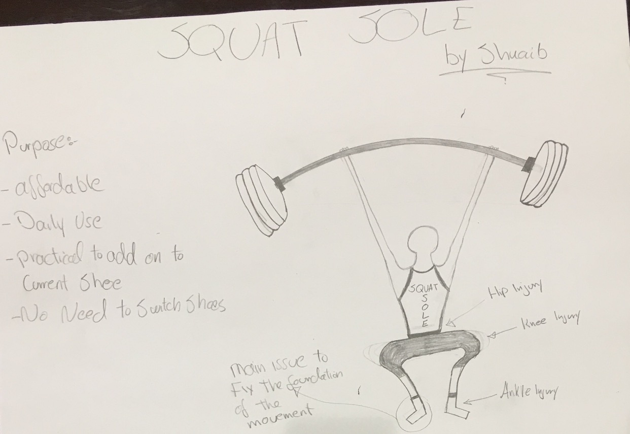
Most of the people we witness everyday at the gym are trying too hard to train but in fact they are getting themselves hurt. People at any gyms and especially the beginners tend to forget the main concept behind performing the squatting which is the quality of the movement. not limited to hip injuries, knees injuries and ankle mobility issues, the concept of the SQUAT SOLE is to solve those issue and reach to quality movement when performing the SQUAT
then the concept has developed into creating a peep sound and LED Light to alarm the person performing the squat that their movement is correct. One of the main purposes here is that the person performing the squat will not have to switch their shoe to a squat shoe in order to perfect the movement. All they had to do is put the external sole underneath their gym sneaker, lace up the strap, and SQUAT.
Furthermore, the purpose of the LED is extra for the cases where a personal trainer or a partner is trying to notice the squat movement and will be notified that the squat is performed well. the LED light could also be used for those who film themselves while training. another reason is to be used by those who have difficulties in hearing.
Future Concept Development
1) One future plan to develop the Squat Sole is to add 2 more sensors in each area of the squat sole and connect the micro controller to a blue-tooth device and show the whole process of foot pressing in the mobile device. I am planning to develop this feature once the project submission is complete.
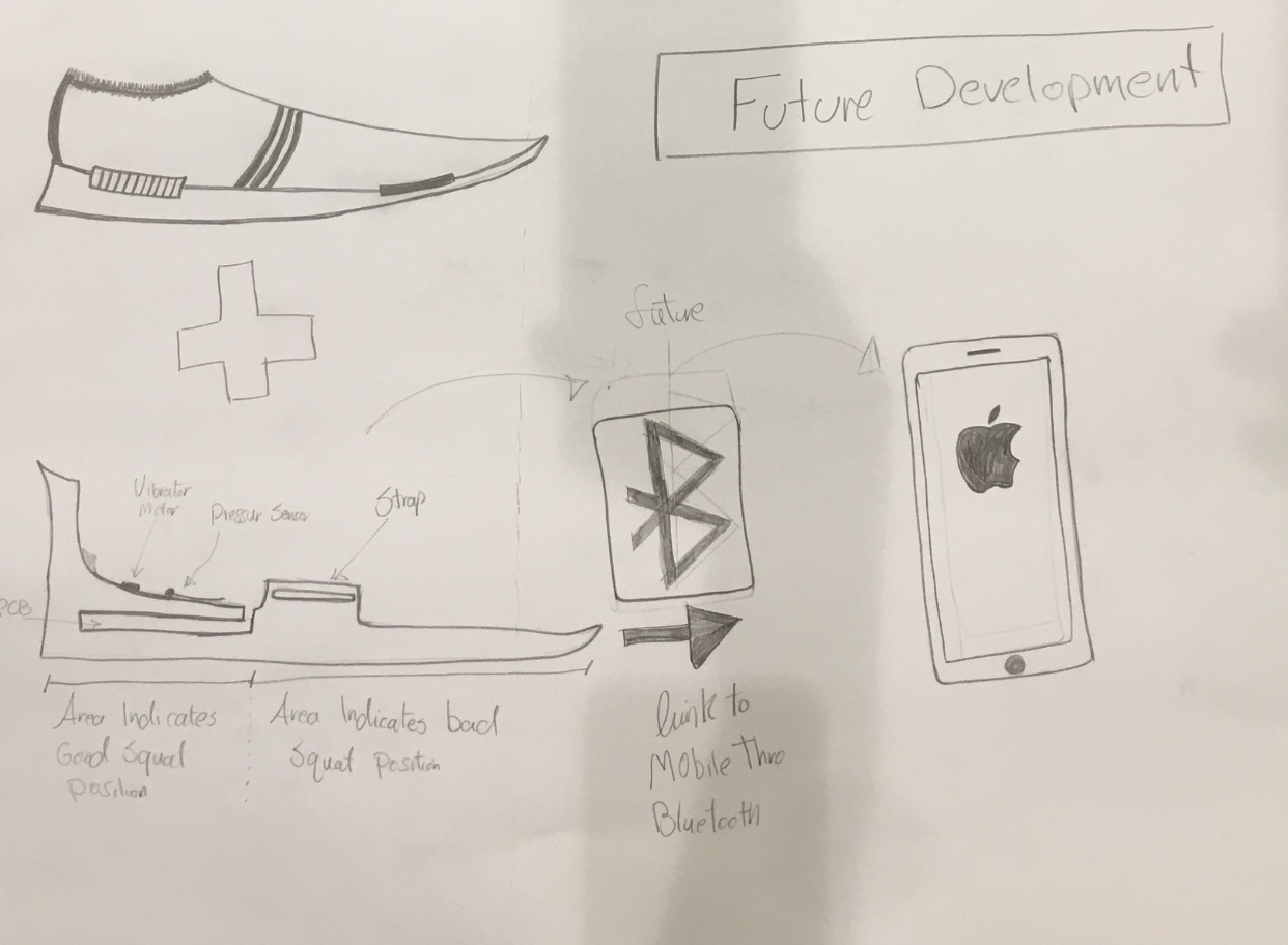
2) Another future development is to add the person weight in the application itself in order to readjust the value of the pressure in the pressure sensor. furthermore, we can add a weighing sensor and based on the output of that sensor we can switch he sensitivity level of the sensor based on the weight of that person.
3) Due to the limitation of a good 3D printer in our lab, I had to slice the squat sole in 3 pieces. The best way to print the squat sole in 3D is to print it in ONE piece. So in better cases with a better 3D printer in the lab, printing the Squat Sole in one piece is the best option to avoid a chunk of the assembling process.
Design Process
1) The design has been developed further in the Onshape software on-line to match the height of the squatting sole including a strap to be wrapped around the foot.
2) Dimension of a size 46 UK was taken in order to match the same size in the design.
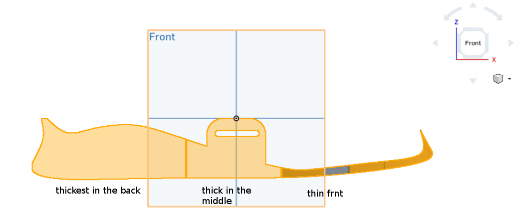
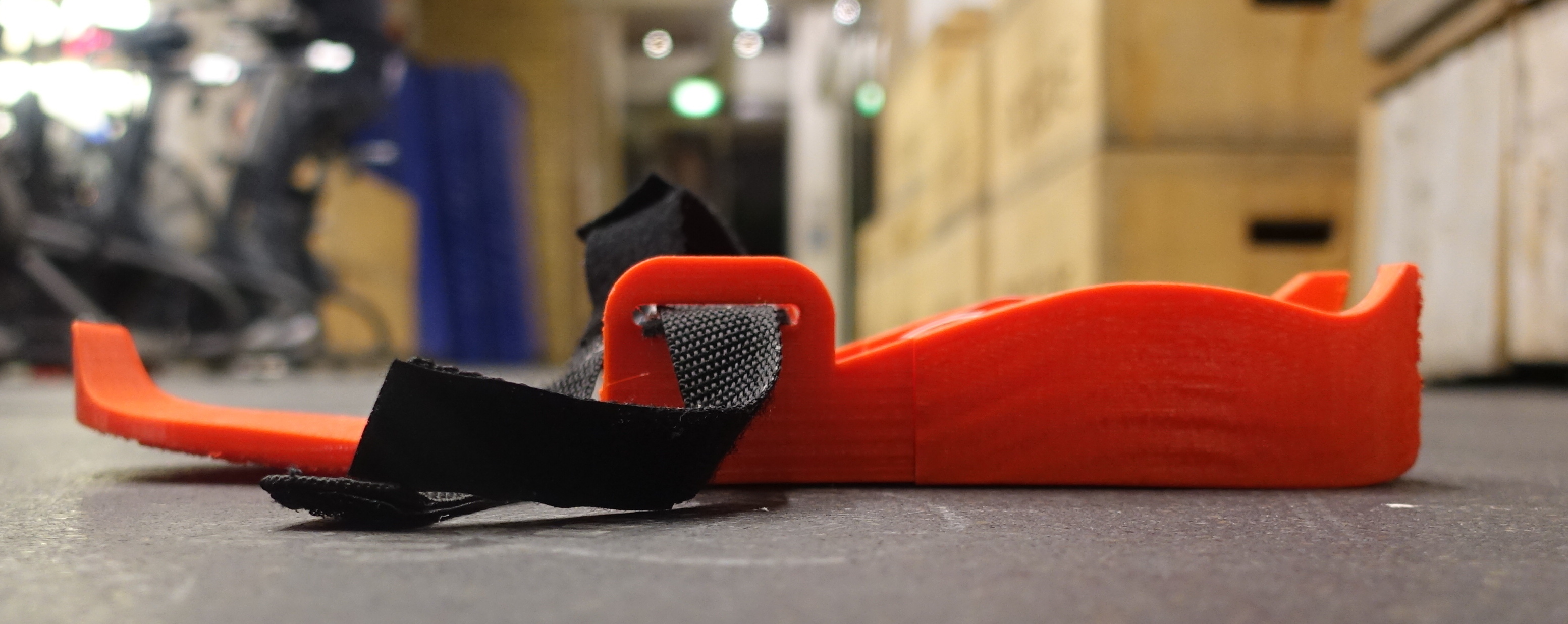
3) The front part of the sole was design to be thin enough to match ay squat shoe dimensions
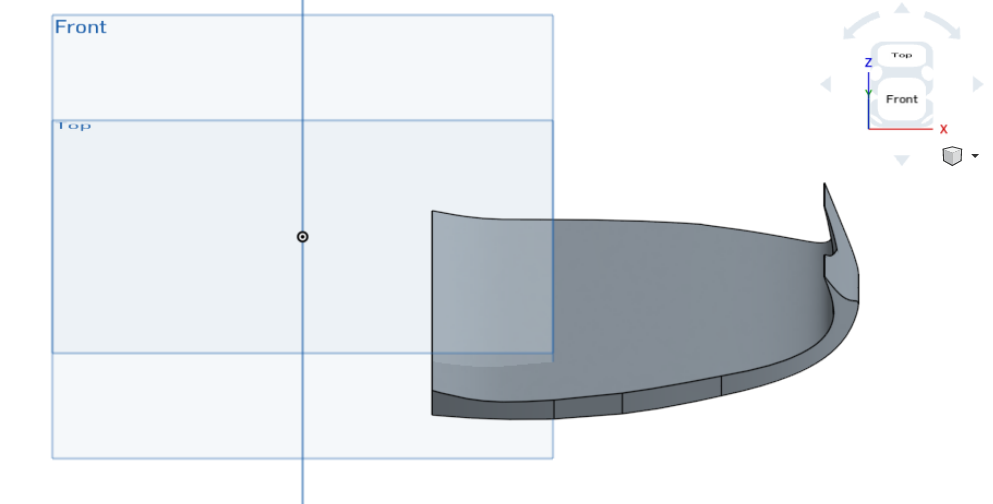
4)As we go further to the heal, the height of the sole increases as seen below.
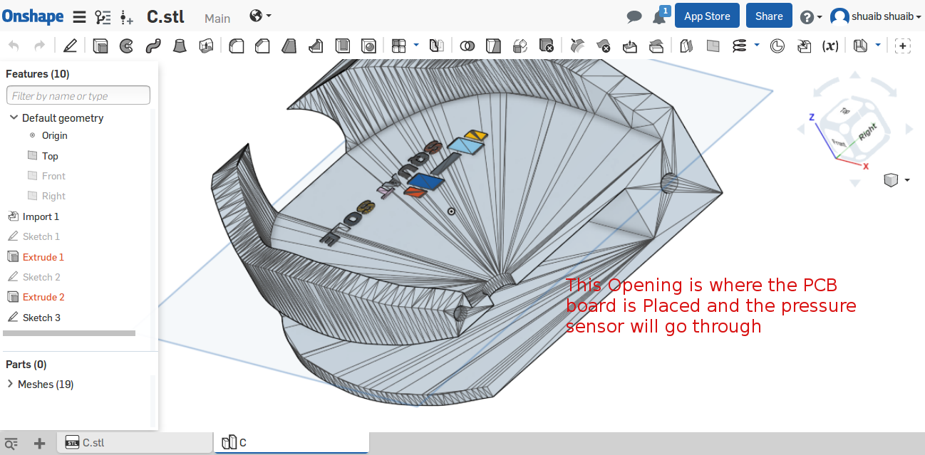
5) On the side of the design we can notice a 1 cm height with a 5cm by 9 cm space located in the heal. The dimension are based on the PCB dimensions to allow the PCB board to fit in the space firmly.
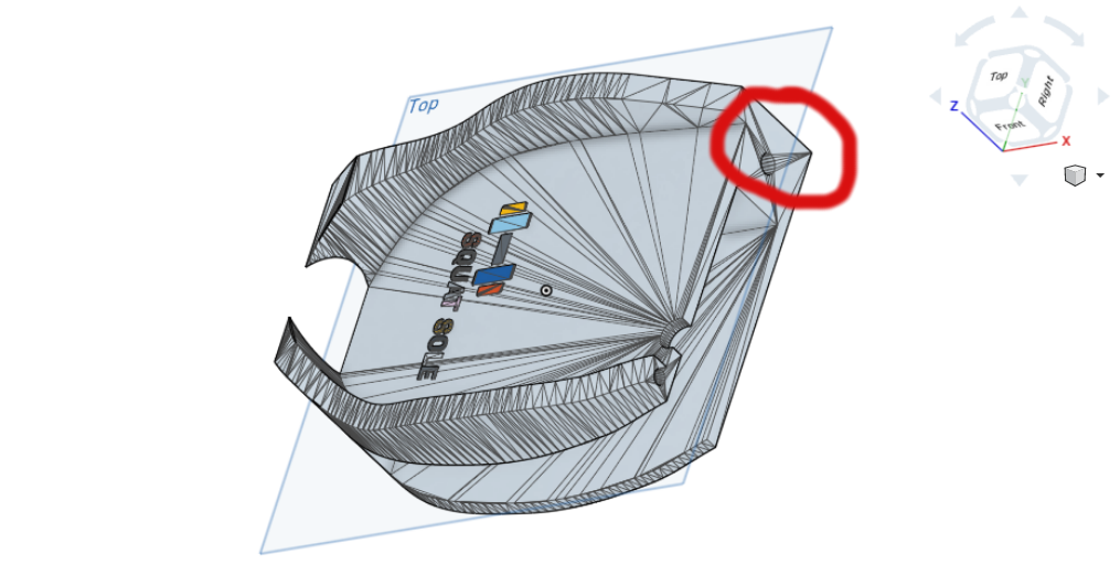
6) Then i included a 1cm diameter hole to pass through the wire that will be connected to the pressure sensor located in the heal portion of the sole.
.png)
7) I have added a male and female connection to assemble the 3 pieces. the same concept is applied for the connection of pieces 1 & 2 the 2 & 3.
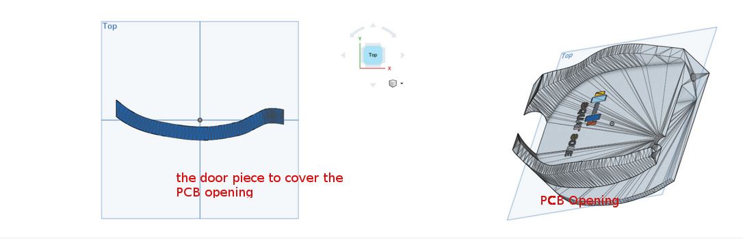
8) I added an extra door piece that should cover the side of the PCB opening as well
9) I have extruded in the logo on the top of the heal
![]()
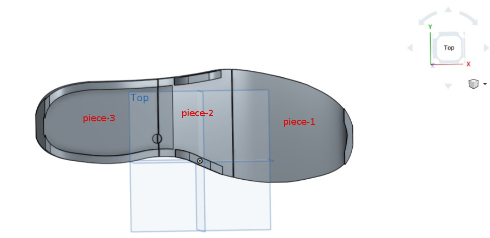
10) The i had to slice the sole into 3 pieces as seen below in order to ft into the 15cm x 15cm size base of the printer:
Design Files
Here are the ONSHAPE files for a pair:
4 pieces of the Pair :
Piece-A CLICK HERE.
Piece-B CLICK HERE.
Piece-C CLICK HERE.
Piece-D CLICK HERE.
The Bill of Materials for 2 soles (BOM)
2 ATTiny 45
2 Pressure sensor
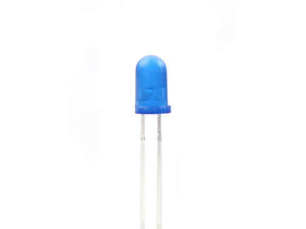
2 LED Lights
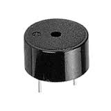
2 Piezo Buzzers
2 NPN transistor
4 Capacitors
2 10K Resistors
6 1K Resistors
4 Cr2032 battery holder
4 Cr2-32 battery
2 5V regulator 1117
2 Stabilizing caps
total estimated cost for 2 pairs = $90
3D Printing
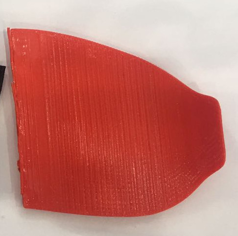
I have printed each part separately due to the size of the base of the printer which only allows us to print a 15cm by 15cm maximum area. the height was good enough to print the files and convert them from STL to Fcod. Below are the pictures of the each piece printed separately:
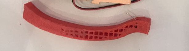
Here is the Last trial of printing the squat sole
Electronics Design & Production
Input:
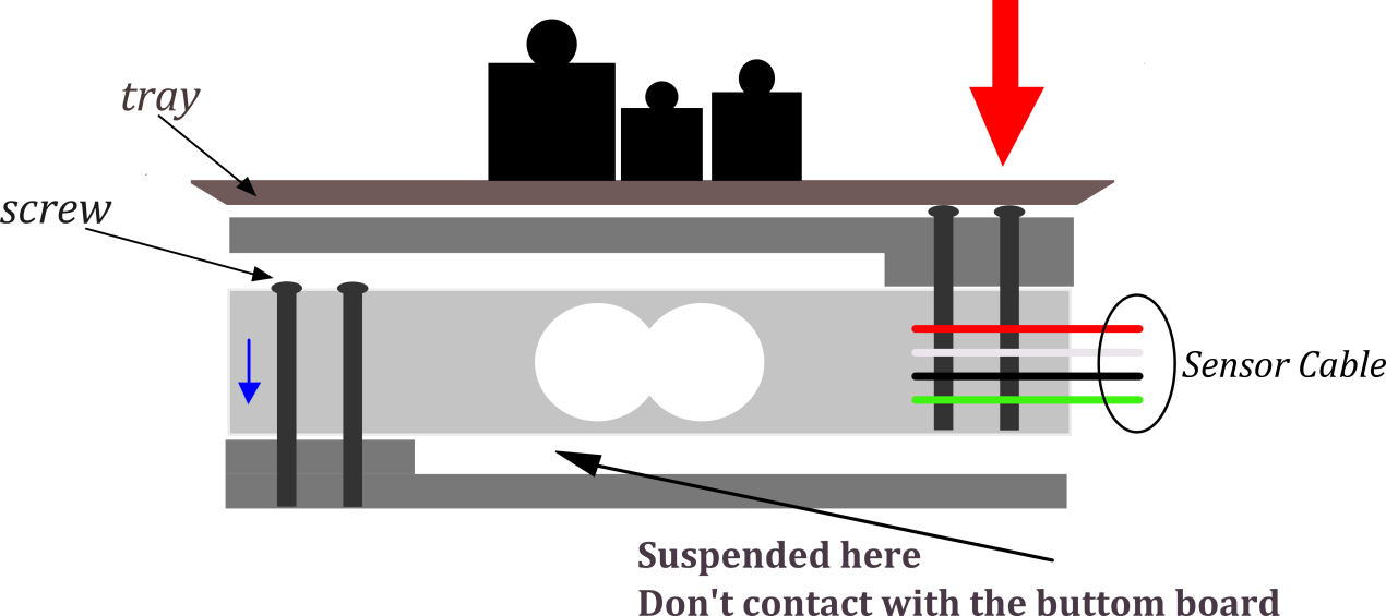
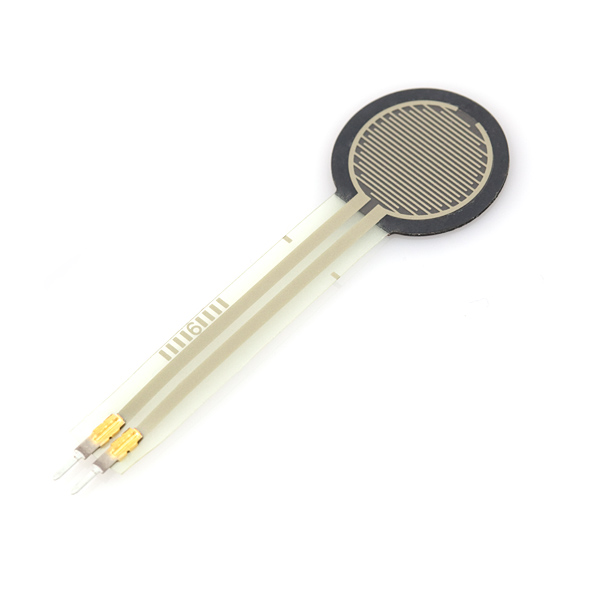
I Have used the pressure sensor Force Sensitive Resistor 0.5" model as seen below in my project to sense the value of the pressure required in order to start the flow in the circuit. the description below is taken from
www.sparkfun.com
Description: This is a force sensitive resistor with a round, 0.5" diameter, sensing area. This FSR will vary its resistance depending on how much pressure is being applied to the sensing area. The harder the force, the lower the resistance. When no pressure is being applied to the FSR its resistance will be larger than 1MΩ. This FSR can sense applied force anywhere in the range of 100g-10kg.
Two pins extend from the bottom of the sensor with 0.1" pitch making it bread board friendly. There is a peel-and-stick rubber backing on the other side of the sensing area to mount the FSR.
These sensors are simple to set up and great for sensing pressure, but they aren’t incredibly accurate. Use them to sense if it’s being squeezed, but you may not want to use it as a scale.
Sensor Value Testing
So using Audrino serial monitor to grab an idea about the value range of the sensor in terms of the weight required to be set for the sensor. Here is a video for the pressure sensor programing. Please refer to the TESTING section for the code used.
Output:
I am using buzzer and LED as an output for my project. The purpose of using LED & buzzer is to notify the user in different ways that the squat is performed correctly in the essence of the ankle movement. So technically, the LED and Buzzer are set to be activated when the season value reaches the intended number.
I have done a small research about about the Piezo Buzzer that I have used and found out the following interesting facts. piezo was discovered in the 18th century 2 brothers Pierre and Jaques Curie. the principle of the Piezo material is that it generates electrical wave once mechanical pressure is applied. the concept has been developed to a sound output as well. So Piezo Buzzer is normally used to alert by the buzzer sound when its connected. its very affordable to be used in small structures that require sound output and very light in weight as well. Piezo buzzers are usually used in computers, call batteries, and construction trucks
PCB Design
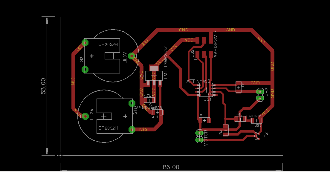
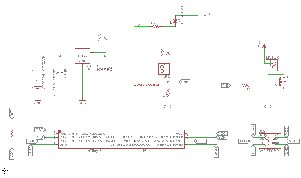
The PCB Design Including LED light and added another small circuit for the buzzer and connected it to the LED light in the ATTiny switch so they can work together once the pressure is applied. here is a hero shot of the design (schematic and board).
Here is a step by step detailed design process of the PCB:
1) in The Circuit Diagram, the pressure sensors pins are connected to a VCC and a Ground. As seen below, across the sensor and the ground connection, i connected the SHB pin to the micro-controller in pin PB4 which is analog pin. Seethe red circles below.
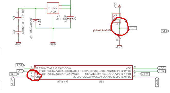
2) In the circuit Diagram, the LED pins are connected to a ground at one end and a VIB pin in the micro-controller PB3.
3) the next step is that I connected the buzzer to into a VCC and the other pin is connected to a VIB pin as well (so ignore the MOSFET end of this part since the originl vibrator motor concept was eliminated and switched to Buzzer)
4) please note that both LED and 5V to reduce the total voltage exposed to the circuit from 6V to 5V.
5) So the voltage regulator 3 pins are connected to the batteries output, Ground and VCC.
Here is the Final Board file. HERE and this is the Final Schematic file. HERE
PCB Milling & Soldering
Milling and Soldering of the PCB and the issues faced:
- The main issue was faced after milling and soldering the PCB components was that the size of the battery holders. i had to fix them in the back of the PCB to create enough space for the board to fit within the shoe.
- another issue was that the Resonator selected during the design does not match the ones we had available in the lab, so i had to do the external connection as seen in the pictures below.
- the final issue was the height of the 2x3 header used fr the programming is too high for the 1cm width of the PCB pocket within the Squat Sole. So I had to remove it after programing all the three codes and finalized the testing process.
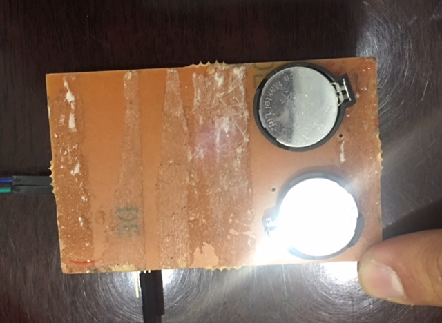
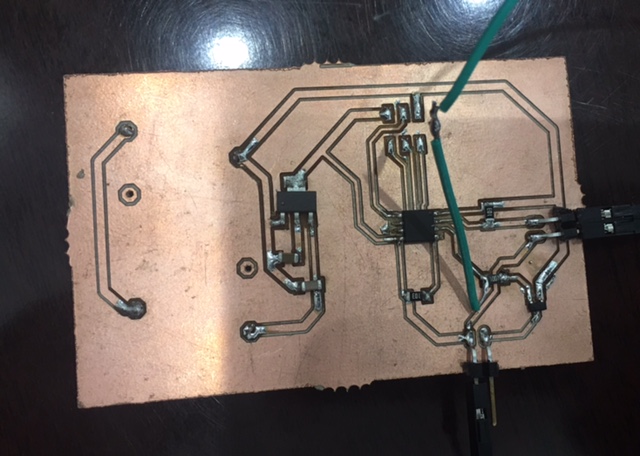
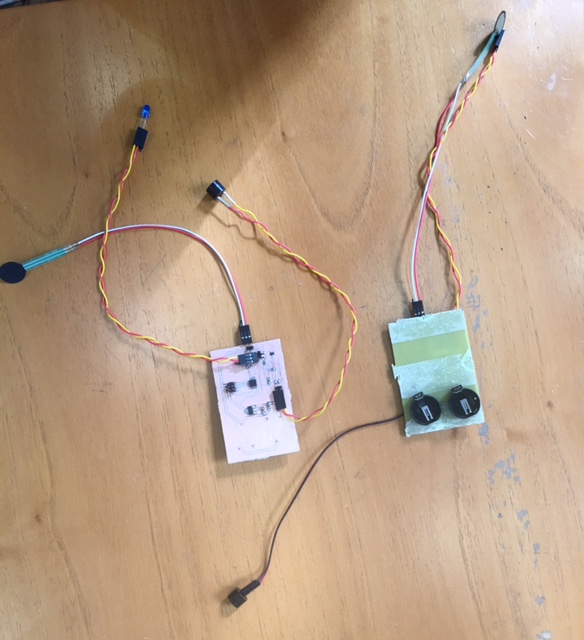
Below are the 2 PCBs of both left and right pair that were milled and soldered for the 2nd run including the LED light and the buzzer instead of the vibrator motor. please note that the battery holders were placed in the bottom of the board as well.
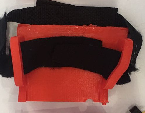
The connection between the 3D printing and electronics
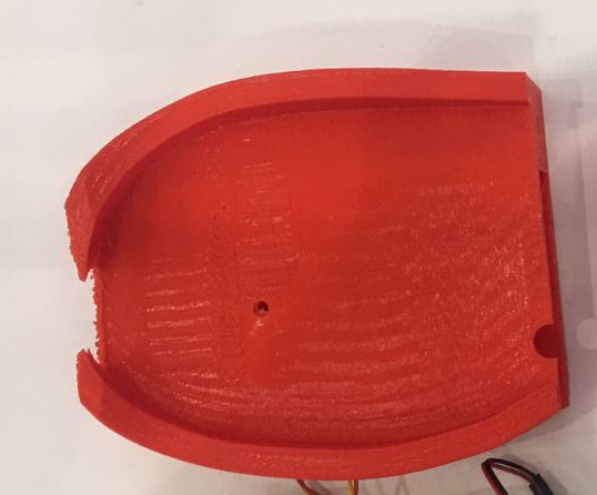
in the picture below, I have designed a space where I can fit the PCB board as mentioned earlier and made an opening where the pressure sensor will go through that opening and be placed on the heal to sense the pressure applied.
the movement of the PCB board inside the PCB-Opening will not affect the product much because of the nature of the squat sole s not to run or jump wth it, but rather to perform a stationed movement in the vertical direction (up and down) ONLY.
Testing
the video below shows the testing I've done for the CB connection BUT i have tested the board with an LED light just to make sure the connection exists and to save time to move on to the next step until i receive the vibrator motor requested. The code in the page attached and here is the video:
Final Connection Testing Video of LED and Buzzer of the 2nd trial
here is a video of the final test after replacing the LED light and the Buzzer for the vibrator motor
Assembling/
1) as seen below, I have added an extra hole next to the SQUAT SOLE LOGO for the pressure sensor to go through smoothly and be placed under the heel.
.jpeg)
2) I have fixed the male/femaleconnection with a little bit of a super glue in between to avoid the collapse of the product. i would highly recommend to print the product in 1 Piece if a better 3D printer is availbe in the lab.
3) below is how to fix the electronic parts in the space provied for the PCB and the whole located on the side for the LED to be visible.
Issues Faced
Normally, the Squat Sole is used to perform a squat movement which is standing in place and moving up and down in vertical direction as seen in the video below. so the Squat will require a stationed movement going vertically where the feet are in place planted on the ground. Since most of the pressure is applied at the heel where the thick part is located, the pressure should enough. In the cases of printing the 3 Pieces in a bigger 3D printer, The Squat Sole will be more rigid and fixed to apply higher pressure.
So the main issues faced in this project are the following:
1) fixing all 3 parts in a male/female cnnection. having a better 3D printer will allow me to print it in one piece.
2) The size of the PCB to be reduced along with the size of the PCB space under heel as well.
3) Design the space are to best fit the PCB board and making sure the board is not moving.
anther option to avoid all of the above is to use molding and casting approach in the heel area. Moreover, I'd use composites for a more rigid shape.
The Codes
1) Pressure Sensor Value Testing
// initialize serial communication at 9600 bits per second:
Serial.begin(9600);
}
// the loop routine runs over and over again forever:
void loop() {
// read the input on analog pin 0:
int sensorValue = analogRead(A0);
// print out the value you read:
Serial.println(sensorValue);
delay(1); // delay in between reads for stability
}
2) Connection Testing code
int sensorValue = 0;
void setup() {
// declare the motorPin as an OUTPUT:
pinMode(motorPin, OUTPUT); }
void loop() {
// read the value from the sensor:
sensorValue = analogRead(A2);
if (sensorValue > 512) {
digitalWrite(motorPin, HIGH);
delay(1000);
}
else
digitalWrite(motorPin, LOW); }
3) LED and Buzzer Code - Final Trial
In this code, we can set the value of the pressure to be based on the weight of the person. the more pressure is required for a heavier person. in this case, in a size 46 squat sole, i have set the value of a pressure to be read when it reaches 255 at the command of:
(if (sensorValue > 250)) in the code below.
int alert = 0;
void setup() {
pinMode(ledpin, OUTPUT);
}
void loop() {
digitalWrite(ledpin, LOW);
int sensorValue = analogRead(A2);
map(sensorValue, 0, 1023, 0, 255);
if (sensorValue > 250)
{
if (alert == 0) {
alert = 1;
digitalWrite(ledpin, HIGH);
delay(100);
digitalWrite(ledpin, LOW);
delay(100);
digitalWrite(ledpin, HIGH);
delay(100);
digitalWrite(ledpin, LOW);
delay(100);
digitalWrite(ledpin, HIGH);
delay(100);
digitalWrite(ledpin, LOW);
delay(100);
}
} else {
alert = 0;
}
}
}
Websites Used for Logo Desig
here is the website used to design the logo of the prject www.canva.com.
Websites Used for Converting MP4 to YouTube
here is the website used to convert the youtube files into mp4 format and post it in the final project page http://en.savefrom.net.
The Previous Weeks Used
1) Commercial Board Policy Week : by using the fab lab standards and Udrino system through out the whole project
2) Principles and Practices, Project Management week: created the project page and managed the project through a clear progress in a short period of time
3) Computer-Aided Design week: used Onshape online software to design the 3D shoe sole
4) 3D Scanning and Printing week: printed the 3 pieces of the shoe sole in the 3D printer
Electronics Production week: Designed a circuit, milled it, soldered it and finally programmed it.
5) Electronics Design week: connected an LED light to my circuit to demonstrate that the circuit is working perfectly with the coding program used.
6) Embedded Programming week: programmed the PCB through the micro-controller
7) Input Devices week: integrated the input in the programming of the micro-controller through the pressure sensor
8) Output Devices week: was basically testing the PCB with an LED an then the vibrator motor as an output device.
9) Invention, Intellectual Property and Business Models week: by selecting one license entity to secure the license for my project which was the creative common
10) Project Development week: the most important week that aided me to have control over the short prject period and the low cost involved.
Acknowledges Work Done by Others
The local instructors have helped me in transferring the files from STL format to the Fcode format to be compatible with the 3D printer we have in the Kuwait Fab Lab and the coding set up only. The bottom part of the website was also touched by one of the instructors to create a box for the code details to look neater. The development of the 3D design by adding the male and female connection with the logo on top on the heal as well.
This Project is licensed under Creative Commons CC-BY-SA
here is a short 1:00 minute video about the project