Week-7: Computure Controlled Machining
The 7th assignment in the Fab Lab was to do the following and report every step taken during the process.
Learning outcome
1) Document the process of design and production to demonstrate correct
2) work flows and identify areas for improvement if needed
Have you:
1) Explained how you made your files for machining (2D or 3D)
2) Shown how you made something BIG (setting up the machine, using fixings, testing joints, adjusting feeds and speeds, depth of cut etc)
3) Described problems and how you fixed them
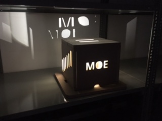
4) Included your design files and ‘hero shot’ photos of final object
The Cubical Lamp Design
Design Process : General Design Requirement and Inspiration
The design was inspired a light lamp for kids that would make cool surroundings once its lit. the concept design behind it is to reflect the shapes or the kids name and letter on the wall as well. Onshape On-line software was used when the cubical lamp was designed. here is some general requirement for the design:
1) The design process learned in the previous weeks was used in this week to start off the design from the cubical lamp.
2) all files were extruded in 1.8 cm 3D to check all the components.
3) Each part of my design was created separately.
4) The design dimension is 25 cm height by 30 cm height and width respectively.
5) the concept of the cubic lamp is to learn how to design and fix wooden pieces interlocking with each other.
6) I have used a feature to uplift the design of the shapes to a linear repeated squares on the side of the square.
7) The depth of the board was described in th software as 1.8 cm and the home screen was set to be located at the bottom left of the board
8) The art cam software was used to transfer the files to CAM format as shown in the picture below to be used in the CNC machine. .
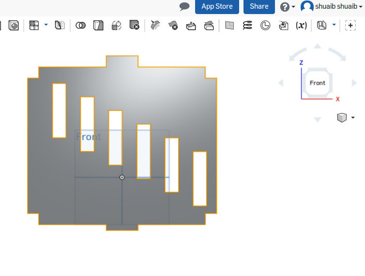
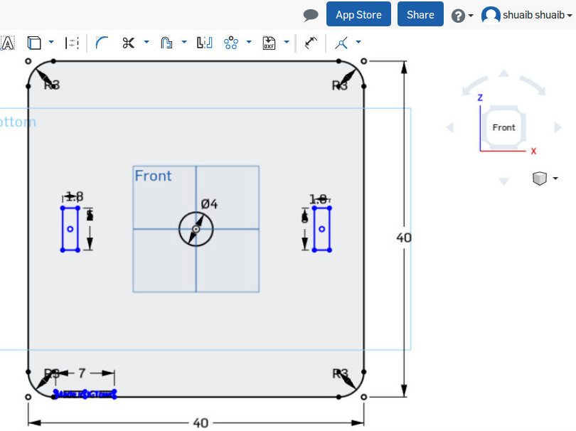
Design Process : Rectangular Side of the Cube
1) a squered shaped design was used in all 3 parts of the cube
2) a 30 by 25 cm square cube was designed in 4 sides
3) here i have used the first side of the lamp that was inspired by a square shape to reflect the details on the wall once the light is on.
4) Thickness is 1.8 cm to make sure that this side of the box will stick smoothly into the bottom and top piece of the cubic lamp.
5) the corner was trimmed into a 1.7 cm to make sure they interlock with the other 2 sides of the next element in the next picture.
6) I have extruded the design at a width of 1.8 cm to to check that all openings will be printed and visible.

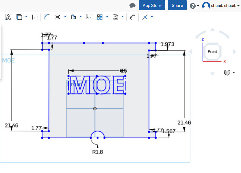
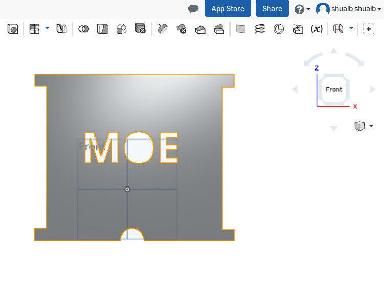
Design Process : Text Side of the Cube
in this step, its the other 2 side of the cubic lamp which includes only the initial of my son Mohammed ,MOE. i did not add any male/Female elements to be interlocking with each other since i have used it in the other 2 sides designed above. th same concept of the previous steps were used but in this case i used the letter MOE to reflect the lights on 2 sides of the lamp .
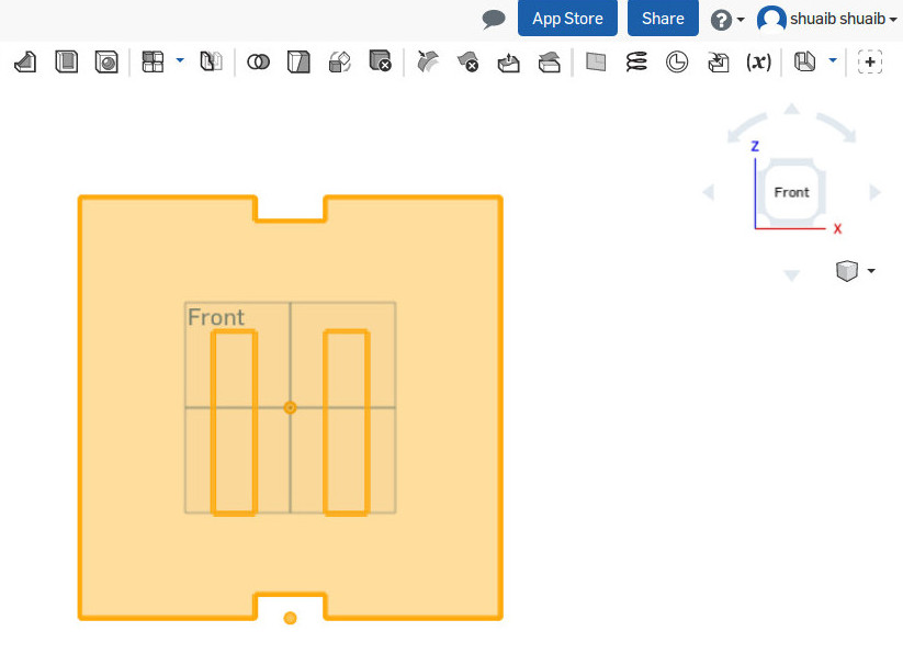
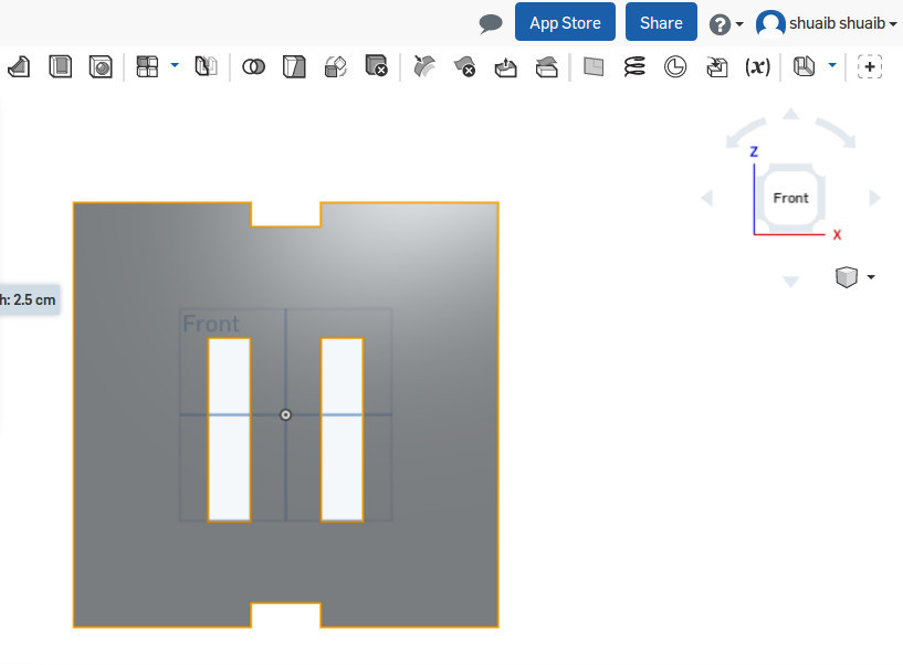
Design Process : Top Part Design - Handles
in this image, it is tough to imagine the role of this element, byt the reason i designed it ths way is to be the top part of the cubic lamp. i added 2 squares on top of it as a handle to remove the top part in case of changing the lamp. on the edges of the shape, i also cropped a 5 cm by 1.8 cm in order to interlock with the 2 side of the cube only and rest on the other 2 sides.
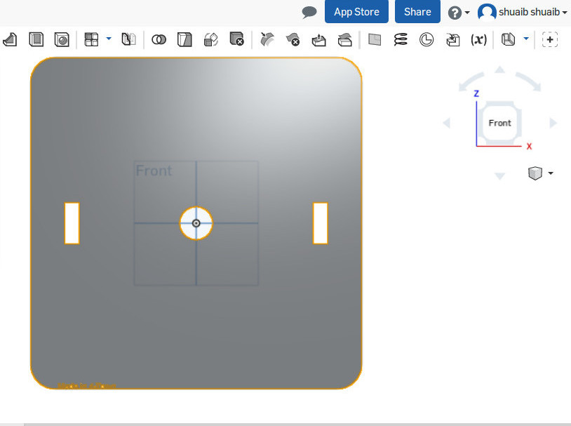
Design Process : Base Part Design - Bottom
the same concept was used for the lower base of the lamp. the base has a 1.8 cm by 5 cm openings that will feed into 2 side of the cubic lamp that wil be placed on top of it. I have also included a wire opening in the middle of it
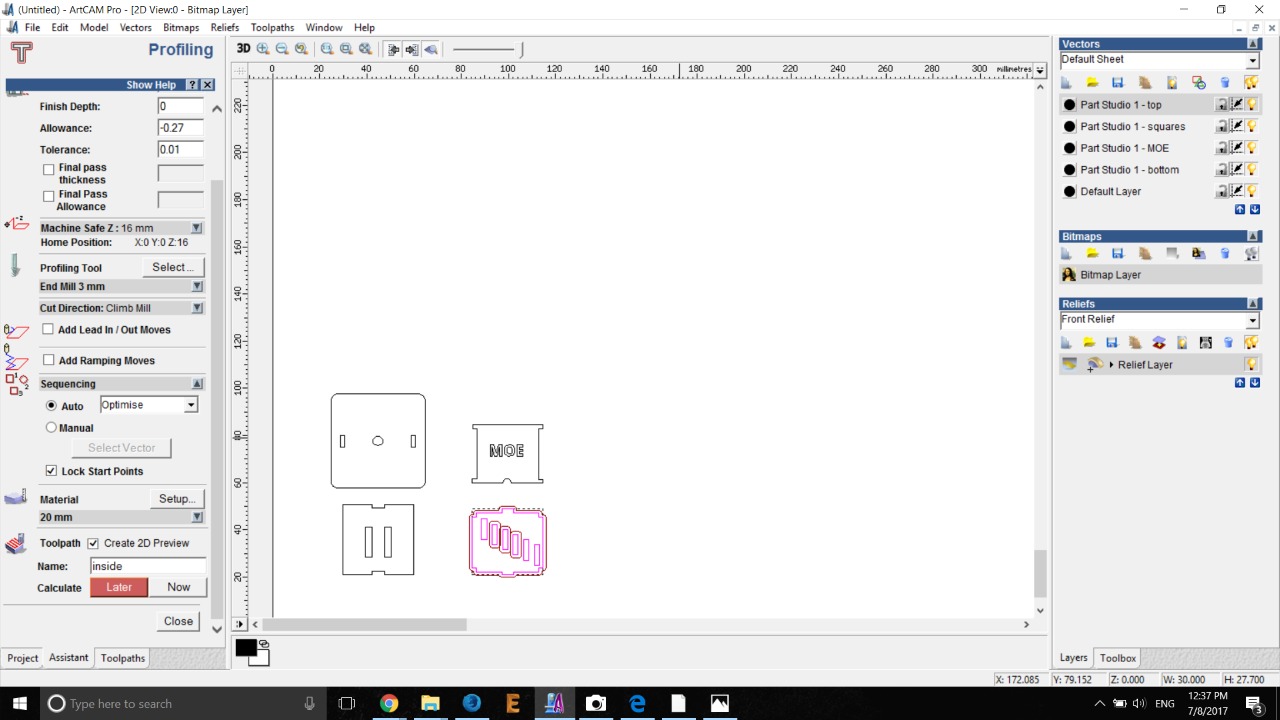
Design Process - How to make Toolpath in Art Cam
1) first i open my design in ART CAM software
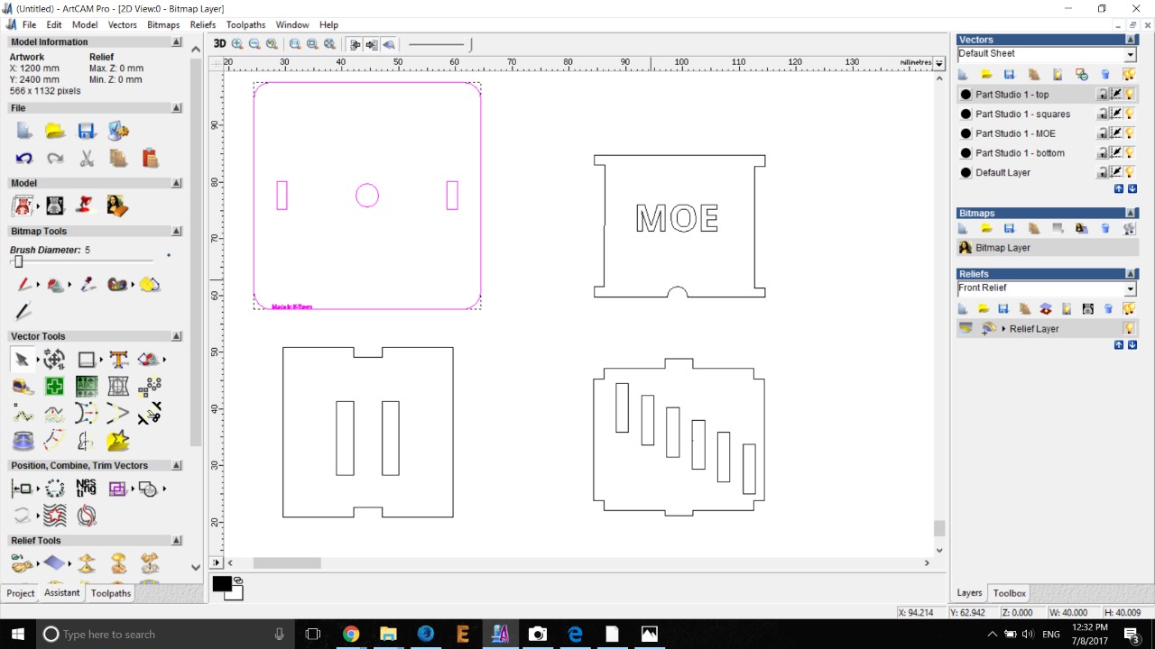
2) I select the design and assigned the toolpath where the CNC cutting is required.on the left part of the software, i assigned the material, thickness, allowance and the stepdown of the CNC and Starting point of the cut.

3) in the picture below, we are using 3.0mm bit for cutting, thats why i select 3mm bit for making toolpath
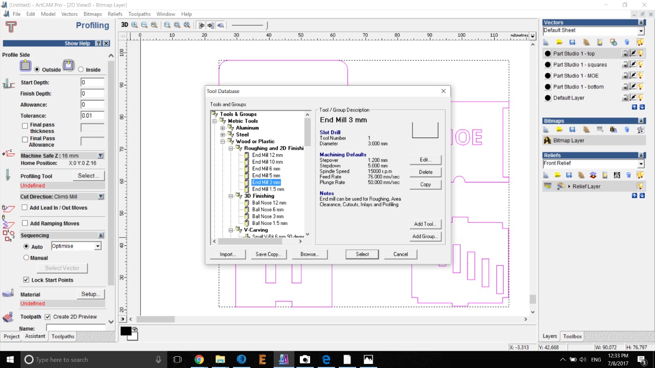
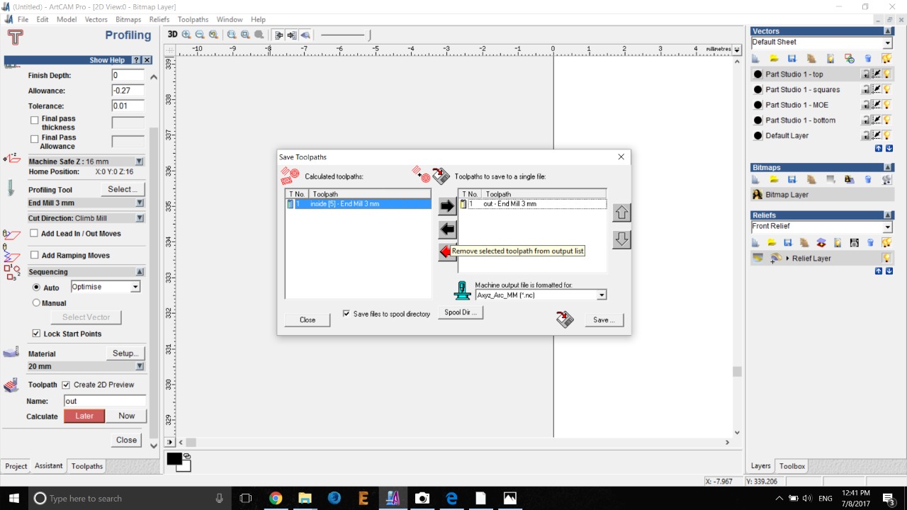
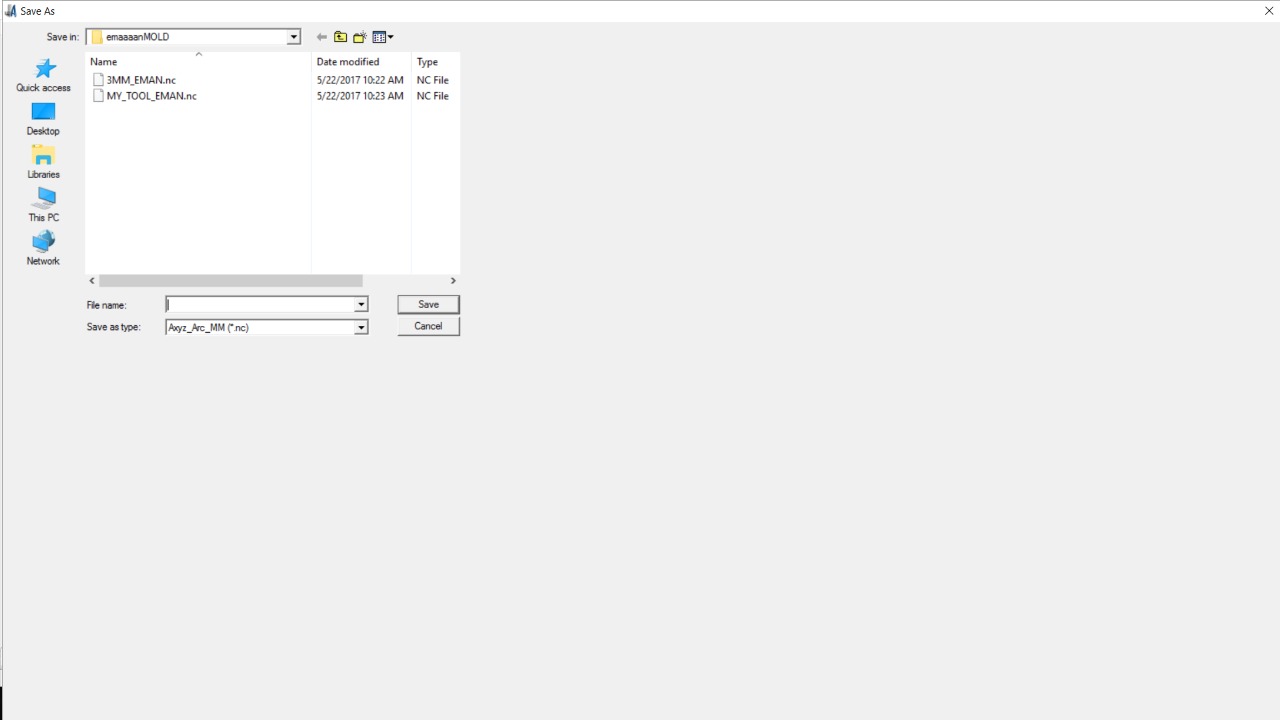
4) Saving the toolpath in PLT format.
Cutting Process - CNC Machine
PLEASE WATCH THE VIDEO BELOW FOR FULL PROCESS INCUDING DIFFICULTIES FACED
the cutting process here was delayed for 3 weeks due missing parts in the machine. the machine was fixed and we carried on with the execution process. The video below is clear enough to show the cutting and assembling process of the CNC machine and the problem faced. The ONLY issue here was that the opening of the base part of the lamp without considering the width of the wood which was 0.19mm in this case. so you can tell that the design wasn't interlocking with each other at the base. so for this par i had to cut a 0.19mm in the base of the lam to make it fit. the video below will show all the details including the problem faced
Problems and Solutions of this Week
1) the first issue here is finding the best idea to accommodate the fablab requirement as described in the assignment BIG. at the same time, i was looking for an element that could be useful to myself and creative enough to fulfill the learning outcome of this week.
2) the opening in the base of the lamp was shifted 1.8cm in one side since i didn't consider that width of the wood as described in the video above. I had to manually cut the 1.8cm to overcome the issue.
NOTE: The video includes the cutting process and explaining the problem faced and how it was solved.
Dsign Files Used
below are the design files i used for each element. the snap shots were taken and posted above in a step by step basis in this week's report
Onshape Link-1 MOE Side
Onshape Link-2 Triangle Side
Element-1 : the bottom art of the lamp. 1 piece is required for this element My File
Element-2 : the part with my son's name . 2 pieces is required for this element My File
Element-3 : the other 2 parts of the lamp. 2 pieces is required for this element My File
Element-4 : this is the top of the lamp. 1 piece is required for this element. My File