WEEK-16: Interface and Application Programming
Have you:
Described your process using words/images/screenshots
Explained the the GUI that you made and how you did it
Outlined problems and how you fixed them
Included original code
About the Interface and application Programming
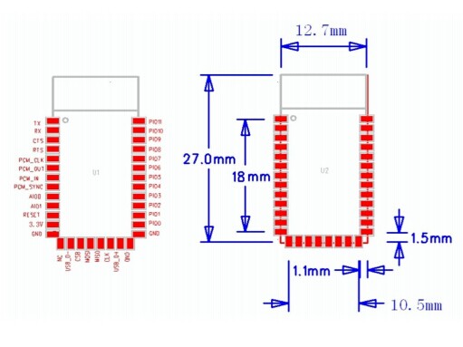
I have read about different types of Blue-tooth connections and ranges and I chose the HC-05 module which was the only model available in the fab lab in Kuwait. below are the specification of the HC-05 Blue-tooth module found in the specification description of it:
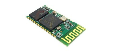
Hardware Features of the HC-05 Blue-tooth module are:
-Typical -80dBm sensitivity
-Up to +4dBm RF transmit power
-Low Power 1.8V Operation ,1.8 to 3.6V I/O
-PIO control
-UART interface with programmable baud rate
-Integrated antenna
-Edge connector
Software Features of the HC-05 Blue-tooth module are:
-Default Baud rate: 38400, Data bits:8, Stop bit:1,Parity:No parity, Data control: has.
-Supported baud rate: 9600,19200,38400,57600,115200,230400,460800.
-device gets disconnected at a rising pulse in PIO0, .
-Status instruction port PIO1: low-disconnected, high-connected;
-PIO10 and PIO11 can be connected to red and blue led separately.
-Auto-connect to the last device on power as default.
-Permit pairing device to connect as default.
-Auto-pairing PINCODE:”0000” as default
-Auto-reconnect in 30 min when disconnected as a result of beyond the range of connection.
-When master and slave are paired, red and blue led blinks 1time/2s in interval, while disconnected only blue led blinks 2time
you can find more details in this link HERE.
The PCB-LED Used
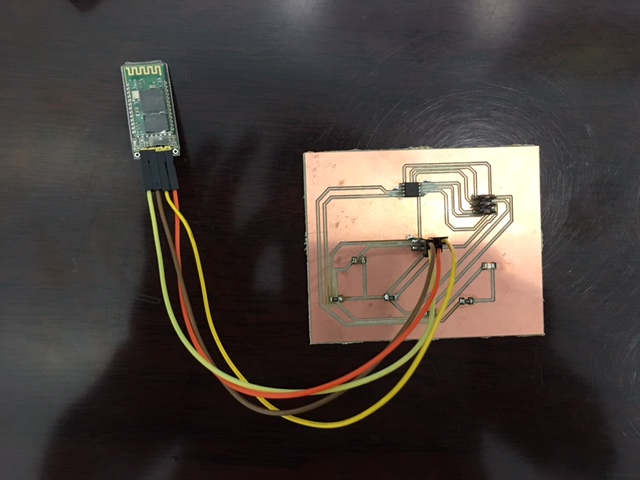
for this week, I had to use the slave board from the previous week which included the following components:
1) Blue LED light
2) 10K resistors
3) 300 watts resistors
4) Capacitor
5) ATT-45 and a 2x3 connector
here is a picture of the slave board tht was done in the previous week-15 and used for this week-16 since it is an LED board already.
and here is the board design used in bard format. HERE
Building The Application
in order to establish a good connection through the Blue Tooth, I had to create a blue-tooth application as required by the the fab lab academy assessment page in an APP INVENTOR.
using the MIT app inventor to create the application and the graphics in the application was a very easy way to complete the task. the application is set for beginners level to be able to create such interaction through blue tooth connection. The application has so many graphics to use from such as the background pictures of the buttons used as seen in my application in the picture below. the application simply transfers the text codes into visual in a drag and drop simple motion.
I created the platform as shown below in the picture including the an ON and OFF button that will read an an ON/OFF of the LED blue light once the connection is established. the picture below shows the final interface of the application with the number 1 and 0 which means the command given to switch on the LED light or switch it off.
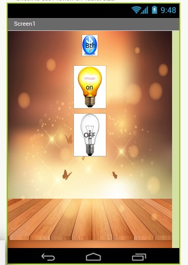
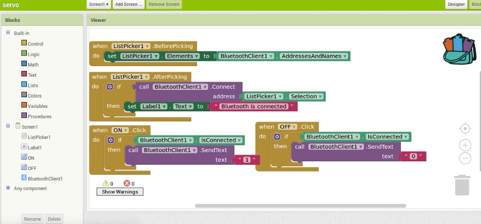
The Blue-tooth type used here is HC-06. The devices here were programmed in the previous step using the MIT blue tooth software provided by the fablab website. more over, the final look of the application created to lit the LED in the PCB board through a Blue tooth platform in an apliction.
Codes Used
Here is the code used CLICK HERE
Here is the GUI Folder CLICK HERE
the concept behind the code is if the user presses the ON button, then ZERO will be read in the micrcontroller and if the user presses OFF, then ONE will be sent to the microcontroler to take the action.
mySerial.begin(9600);
pinMode(4,OUTPUT);
digitalWrite(4,LOW);
}
void loop() { // run over and over
if (mySerial.available()) {
char a=mySerial.read();
if(a=='1'){
digitalWrite(4,HIGH);
}else if(a=='0'){
digitalWrite(4,LOW);
}
}
}
The Results
the video below will show the process of connection the blue tooth device into the application to lit the LED blue light. clicking the yellow light will turn the switch on and reads as 1 in the application. The white light will read as Zero and turns the blue tooth light off. here is the video below: