WEEK-15: Embedded Networking and Communications
Have you:
Described your design and fabrication process using words/images/screenshots.
Explained the programming process/es you use
Outlined problems and how you fixed them
Included original design files and code
3 Types of Networking
Based on the lecture that was given by the local instructors explaining the 3 types of networking we could select from. the 3 types are explained below in the pictures. Therefore, the communication networking types are:
1) Parallel Networking
2) Serial Networking
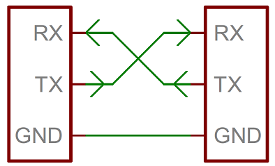
3) I2C Networking
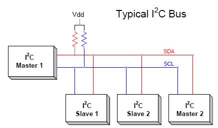
I have selected a simple I2C network to use with master board and 2 similar slave boards of LED light. the light will be blinking in different colors for each board to differentiate between them. The master board will not have a switch bottom but instead will be connected through the computer to give the click command to initiate the action for the slave boards to blink. For the slaves, the same design will be used for both boards and will be milled and soldered identically. a serial bus method was used to connect all boards.
Design of the Network
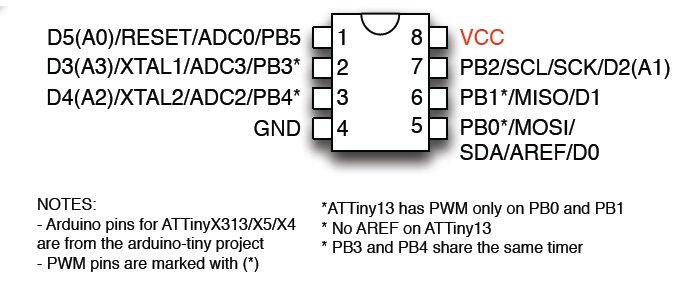
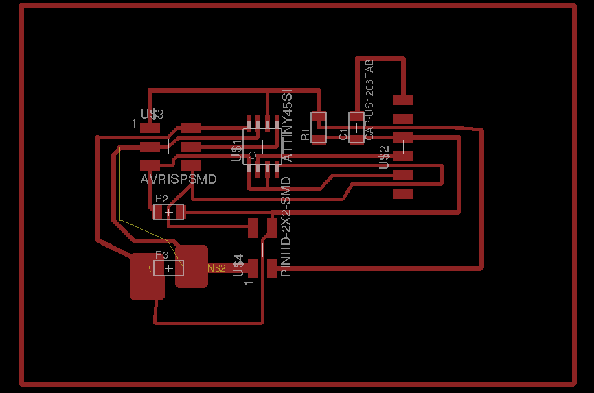
For the I2C communication purposes, we are using micro controller SDA and SCL pin which is pin number PB2 and PB0 as seen in the image below.
Master Board Design
The File in Board format. HERE
the components used here for the master board are:
- 3 of the 10K resistors
- 1 capacitor
- 1 ATtiny45
1 AVRISPMD
- 2x2 header (for communication purposes)
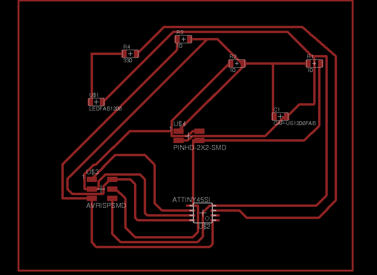
Slaves Board Design
The File in board format . HERE
the components used here in both slaves are:
- 3 10K resistors and
- 1 of the 330 resistors
- 1 capacitor
- ATtiy45
- 2 LED
- 2x2 header (for communication purposes)
- AVRISPMD
Programing the Boards
1) Master Board Code
In the master board, i assigned 2 address of the slave boards before that i downloaded the TinyWireM.h library then I uploaded the code.
in the code i assigned the signal transmitting the slave then dely for a second then transmitting to the slaves boards.
here is the code used . CLICK HERE
void setup()
{
TinyWireM.begin(); // join i2c bus (address optional for master)
}
byte x = 0;
byte x1 = 0;
void loop() {
TinyWireM.beginTransmission(0x1);
TinyWireM.write(++x % 2);
TinyWireM.endTransmission();
delay(1000);
TinyWireM.beginTransmission(0x2);
TinyWireM.write(++x1 % 2);
TinyWireM.endTransmission();
delay(1000);
}
First Slave Board Code
here is the code used . CLICK HERE
in brief, the coade is set to read the LED light to be ON once the signal is recieved from the master board as an input in a blinking format which goes on and off respctivly. I assigned slave-1 board 0x1. for the programming of the slave board, i downloaded slave board library.
direction for output
#define input(directions, pin) (directions &= (~(1 << pin))) // set
port direction for input
#define set(port, pin) (port |= (1 << pin)) // set port pin
#define clear(port, pin) (port &= (~(1 << pin))) // clear port pin
#define LED_PIN PB4
#define I2C_SLAVE_ADDRESS 0x1 // Address of the slave 2
#include TinyWireS.h>
void setup()
{
output(DDRB, LED_PIN);
clear(PORTB, LED_PIN);
TinyWireS.begin(I2C_SLAVE_ADDRESS); // join i2c network
}
void loop()
{
byte recd = 1;
if(TinyWireS.available()) {
recd = TinyWireS.receive();
if(recd == 1) {
clear(PORTB, LED_PIN);
} else {
set(PORTB, LED_PIN);
}
}
}
Second Slave Board Code
here is the code used . CLICK HERE
the code for the second slave is set on the I2C networking as well. it reads from the 1st slave as an input and sets the LED light to be ON once the signal is received from the slave-1 board as an input in a blinking format which goes on and off respectively. Slave-2 board, i assigned 0x2 and i uploaded the code.
direction for output
#define input(directions, pin) (directions &= (~(1 << pin))) // set port direction for input
#define set(port, pin) (port |= (1 << pin)) // set port pin
#define clear(port, pin) (port &= (~(1 << pin))) // clear port pin
#define LED_PIN PB4
#define I2C_SLAVE_ADDRESS 0x2 // Address of the slave 1
#include
void setup()
{
output(DDRB, LED_PIN);
clear(PORTB, LED_PIN);
TinyWireS.begin(I2C_SLAVE_ADDRESS); // join i2c network
}
void loop()
{
byte recd = 1;
if(TinyWireS.available()) {
recd = TinyWireS.receive();
if(recd == 1) {
clear(PORTB, LED_PIN);
} else {
set(PORTB, LED_PIN);
}
}
}
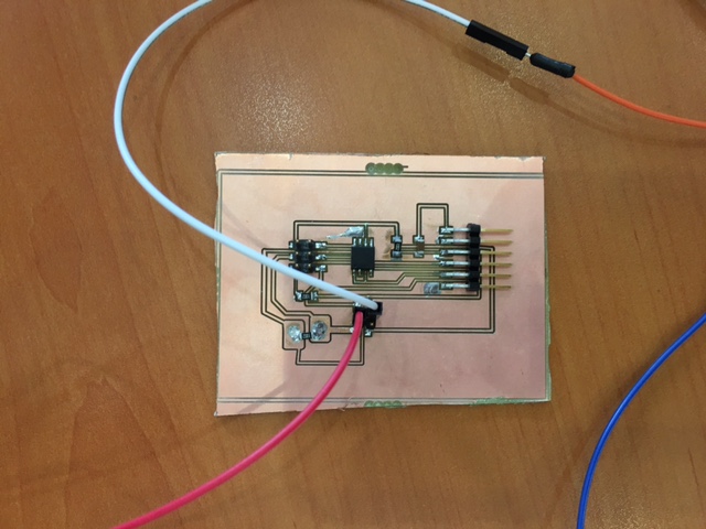
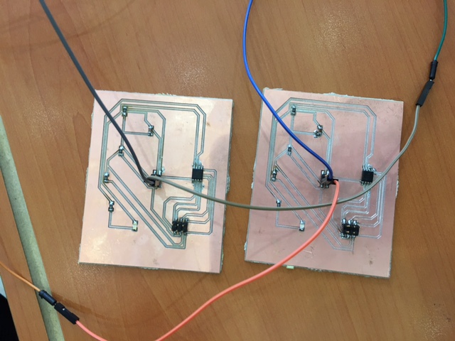
The connection
Then I connected the master with slave boards and the connection is:
SDA to SDA pin
SCL to SCL pin
Ground to Ground
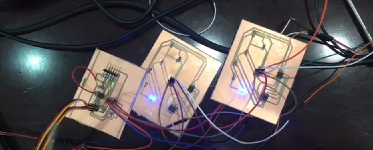
Here is a picture of all the connections and underneath is the video if how the codes and the boards are working. there is more connection between the 3 boards thats why i really confused and in our lap there wasnt any ribon cable
here is a video that shows the programming process