WEEK-13: Input Devices
Have you:
Described your design and fabrication process using words/images/screenshots.
Explained the programming process/es you used and how the micro controller data sheet helped you.
Explained problems and how you fixed them
Included original design files and code
Few Types of Input Devices:
1) Infra-Red Sensors IR: its the type of sensors that can not be visualized with our eyes but could be sensed or felt with our skin.
2) Light Dependent Resistors LDR: depends on the light intensity required, the resistors varies from different type.
3) Ultrasonic Sensors: with higher than the upper audible limit f human hearing, those sensors operate based on sound waves,.
4) Buttons: those input devices are the commonly used in the market. once the button is pressed , signals are sent to the linked micro-controller to read.
What I Did
I am planning to use the PIR sensor in my input board . First of All , I had to research and read more about the PIR sensors in the net and think of how they could be linked with my final project. PIR stands for Passive Infra Red Sensors used to detect human motion mostly. here is a useful YouTube link I found for further details.
so here is the design i selected to work with for this project
Eagle Cad Design
For the PIR sensors board, I have used the ATTINY 45-SI as a micro-controller for my board. The same as the previous weeks, I had to design yet based on the Fab Lab required components such as the capacitor-US 206FAB, resistor R1, AVRISP-MD, HC SR501, FTDI, and JP1.
I started to prefer working on an Auto rout for the design, find my mistakes, increase the tracing channels to 0.22mm and then manually auto route the conflicts in the design and try as much as possible to find any close traces and manually keep them away from each other to avoid any short circuits after the milling.
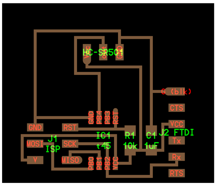
The picture below shows the first step of selecting the design components
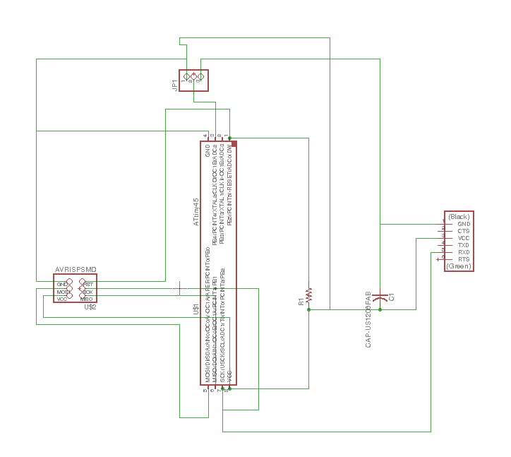
and here is a picture of the final design after the auto routing completion
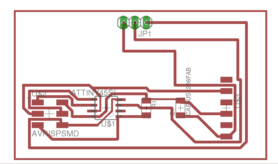
Board File Used . My File
Milling and soldering (Problems Faced)
There is nothing special about the milling and soldering process in this week. Same as the previous weeks, I have milled the board, selected the components and started soldering. BUT a short circuit was found even though the design was 100% perfect , the milling was very neat and the soldering was on point.
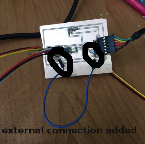
After tracing each channel, I have found out that in the design process, I have connect the GND’s through manual connection and not labeling them. By doing so, you would do a mistake by not fully connecting those traces together and that what happened to me as shown in the design picture below.
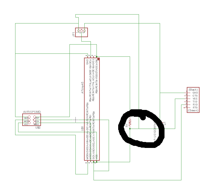
So to fix this issue, I had to externally connect both GND traces to get a 100% connection
Code Used
Here is the file used . CLICK HERE
#include Here is video showing the PIR senors in a working code, Due to havingpeople around, it will keep on sensing us and showing 1's in the programming.
SoftwareSerial mySerial (5,2);
int sensorPin = 4;
int sensorValue = 0;
void setup() {
mySerial.begin(9600);
}
void loop() {
sensorValue = digitalRead(sensorPin);
mySerial.println(sensorValue);
delay(100);
}
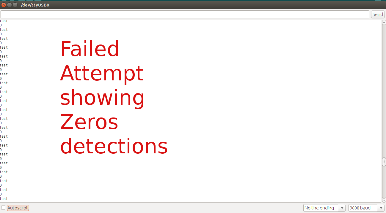
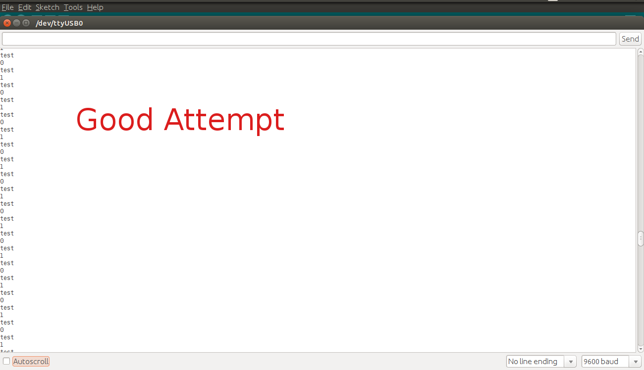
Proof
Moreover, the pictures below shows 2 runs I have done. The first run show a failure due to using a broken PIR sensor, BUT the second run shows success after changing the sensor.