WEEK-10: Output Devices
Design Selection Criteria
in this week, I selected a format that will be used in my final project which is a sound / speaker output. design is completed to this point, milling is done and I am still waiting to collect all the element required to finalize the soldering process
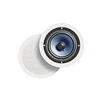
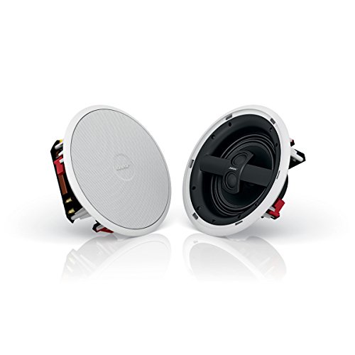
About Speakers Output
the audio output speakers usually receive input from another device in order to work. the audio is usually produced by the sound waves format. most computes and devices have amplifiers built in to control the sound waves level.
Design Process
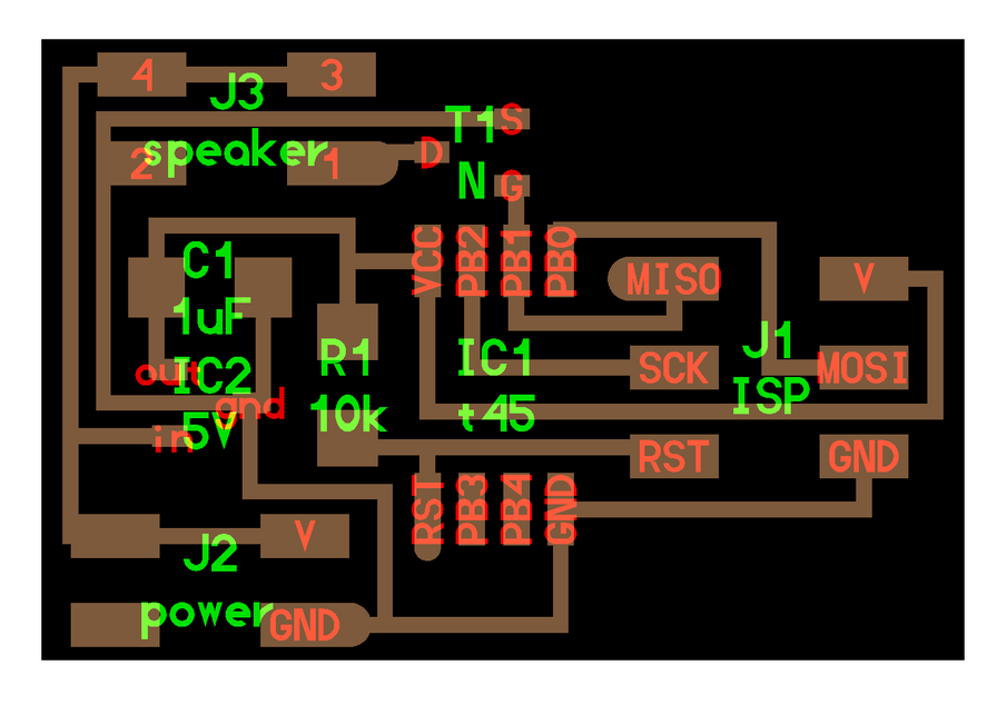
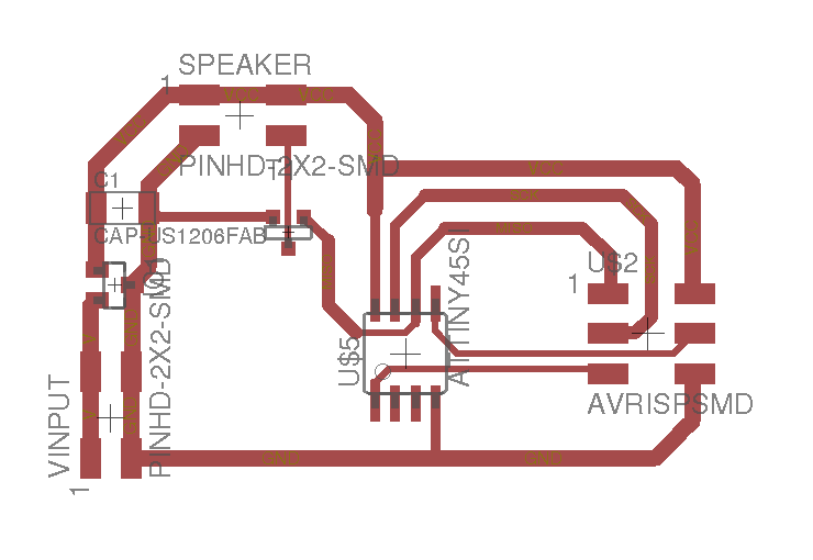
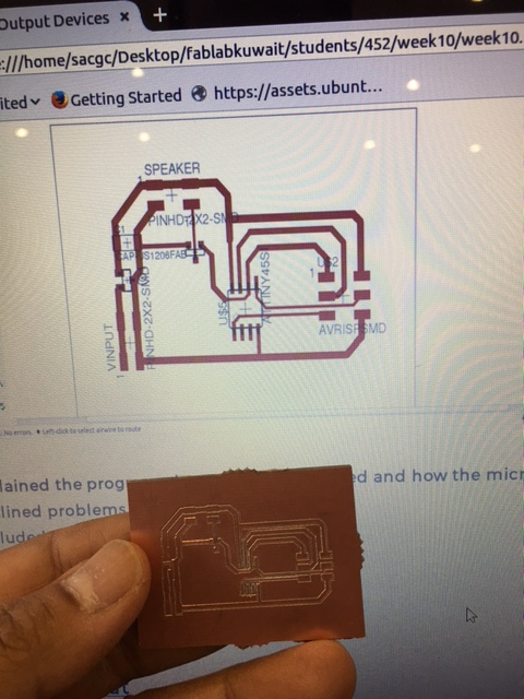
in the picture below, you can find the final design of the circuit prior the milling. I had to play around with the traces width at the setting between 0.016mm to 0.018mm. the rerouting took alot of time to complete so i had to do the tracing manually.
based on the elements available in the lab, i have design the circuit based on the following items:
1) 2 pieces of 2 by 2 headers for the output as well
2) capacitor
3) IC regulator to control the incoming voltage from the battery if its above 5V
4) MOSFET
5) ATTINY 45 s required in the design
6) ISP
Milling Process
the same process was used in the milling process by the setting the device X,Y,and Z axis to have the perfect milling depth in the Z axis. 2 copies were printed as a back up. . the picture below is the milled board.
Citcuit Design BRD an CMP files used
Board File
Fabrication Process
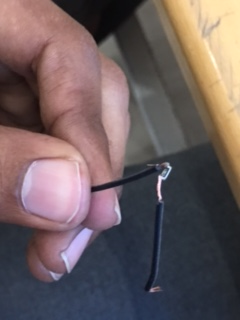
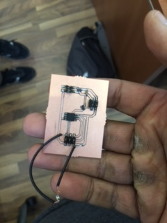
During the soldering process, i found out that the design was missing the resistor component. So I had to add the resistor manually trough an external trace to connect the resistor. The first picture below shows the external connection and the 2nd picture shows the final soldered board
here is my video after programing
Issues Faced During the Process
1) The main problem was the rerouting option in the design process. I was not able to trace the circuit in the rerouting option. after few attempts of either showing 100% due to incomplete connections or 84% due to tracing issues, i decided to trace the whole circuit manually.
2) Short circuit in the 100% manually done design to wide traces. i had to re do it
3) The main issue here is to test the micro controller board while it is on the milling machine. the reason behind it is sometimes the milling Z axis was not deep enough. so i increased the Z depth from -16.24 to -16.20.
4) soldering issues will be stated once the soldering is done
5) The main issue i faced was the missing resistor in the board. so I solved it by an external connection.
6) The sound was very noisy with a high pitch as described in the first video. the problem was in using the ATTiny 45 the internal clock needed to be readjusted through an external clock as an attempt.
The Code Used
Here is the Code File CLICK HERE
/*
Melody
Plays a melody
circuit:
* 8-ohm speaker on digital pin 8
created 21 Jan 2010
modified 30 Aug 2011
by Tom Igoe
This example code is in the public domain.
http://www.arduino.cc/en/Tutorial/Tone
*/
#include "pitches.h"
// notes in the melody:
int melody[] = {
NOTE_C4, NOTE_G3, NOTE_G3, NOTE_A3, NOTE_G3, 0, NOTE_B3, NOTE_C4
};
// note durations: 4 = quarter note, 8 = eighth note, etc.:
int noteDurations[] = {
4, 8, 8, 4, 4, 4, 4, 4
};
void setup() {
// iterate over the notes of the melody:
for (int thisNote = 0; thisNote < 8; thisNote++) {
// to calculate the note duration, take one second
// divided by the note type.
//e.g. quarter note = 1000 / 4, eighth note = 1000/8, etc.
int noteDuration = 1000 / noteDurations[thisNote];
tone(8, melody[thisNote], noteDuration);
// to distinguish the notes, set a minimum time between them.
// the note's duration + 30% seems to work well:
int pauseBetweenNotes = noteDuration * 1.30;
delay(pauseBetweenNotes);
// stop the tone playing:
noTone(8);
}
}
void loop() {
// no need to repeat the melody.
}
Here is the Public Constant Notes
#define NOTE_B0 31
#define NOTE_C1 33
#define NOTE_CS1 35
#define NOTE_D1 37
#define NOTE_DS1 39
#define NOTE_E1 41
#define NOTE_F1 44
#define NOTE_FS1 46
#define NOTE_G1 49
#define NOTE_GS1 52
#define NOTE_A1 55
#define NOTE_AS1 58
#define NOTE_B1 62
#define NOTE_C2 65
#define NOTE_CS2 69
#define NOTE_D2 73
#define NOTE_DS2 78
#define NOTE_E2 82
#define NOTE_F2 87
#define NOTE_FS2 93
#define NOTE_G2 98
#define NOTE_GS2 104
#define NOTE_A2 110
#define NOTE_AS2 117
#define NOTE_B2 123
#define NOTE_C3 131
#define NOTE_CS3 139
#define NOTE_D3 147
#define NOTE_DS3 156
#define NOTE_E3 165
#define NOTE_F3 175
#define NOTE_FS3 185
#define NOTE_G3 196
#define NOTE_GS3 208
#define NOTE_A3 220
#define NOTE_AS3 233
#define NOTE_B3 247
#define NOTE_C4 262
#define NOTE_CS4 277
#define NOTE_D4 294
#define NOTE_DS4 311
#define NOTE_E4 330
#define NOTE_F4 349
#define NOTE_FS4 370
#define NOTE_G4 392
#define NOTE_GS4 415
#define NOTE_A4 440
#define NOTE_AS4 466
#define NOTE_B4 494
#define NOTE_C5 523
#define NOTE_CS5 554
#define NOTE_D5 587
#define NOTE_DS5 622
#define NOTE_E5 659
#define NOTE_F5 698
#define NOTE_FS5 740
#define NOTE_G5 784
#define NOTE_GS5 831
#define NOTE_A5 880
#define NOTE_AS5 932
#define NOTE_B5 988
#define NOTE_C6 1047
#define NOTE_CS6 1109
#define NOTE_D6 1175
#define NOTE_DS6 1245
#define NOTE_E6 1319
#define NOTE_F6 1397
#define NOTE_FS6 1480
#define NOTE_G6 1568
#define NOTE_GS6 1661
#define NOTE_A6 1760
#define NOTE_AS6 1865
#define NOTE_B6 1976
#define NOTE_C7 2093
#define NOTE_CS7 2217
#define NOTE_D7 2349
#define NOTE_DS7 2489
#define NOTE_E7 2637
#define NOTE_F7 2794
#define NOTE_FS7 2960
#define NOTE_G7 3136
#define NOTE_GS7 3322
#define NOTE_A7 3520
#define NOTE_AS7 3729
#define NOTE_B7 3951
#define NOTE_C8 4186
#define NOTE_CS8 4435
#define NOTE_D8 4699
#define NOTE_DS8 4978