1. Redraw echo hello world board adding atleast one led and switch.

2. Show how it is done.

3. Include orginal design files.

4. Fabricate the board.Designing can be done using KiCad, Eagle, Kokopelli, 123D circuits etc.
I thought of using Eagle at first as I had atlease heard about the software previously. :-P But since Kicad was already there in my PC, I thought I should move to Eagle after giving a try in KiCad. I downloaded the libraries for KiCad from the site maintained by Kerala instuctors - Sibu , Easwaran and Yadu exclusively for week6 which was shared to us and we found it very helpful. Especially for someone having little technical knowledge.
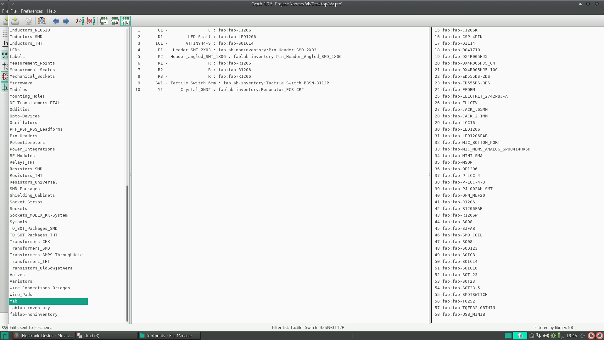
After extracting the fab-inventory and non-inventory files, I copied it kicad folder. Then started working on it after adding these to the kicad library. The steps can be found here.
Then we take the electronic schematic editor. In that we addd the necessary components and give the connections.
The components needed are
ATtiny44
FTDI 6 pin connector
2x3 Connector
Capacitor
Resistor
Resonator
LED
Press button / switch.
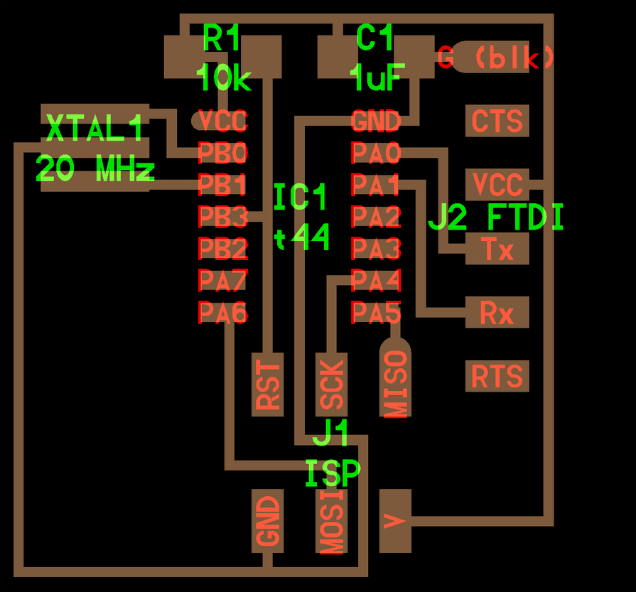
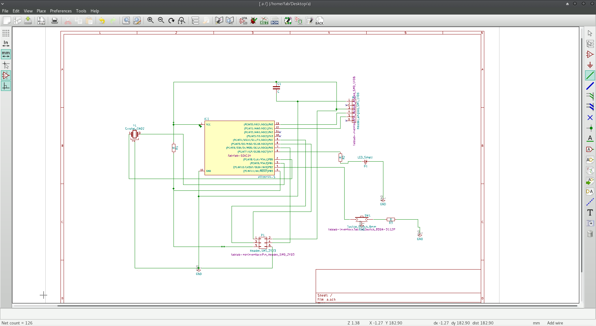
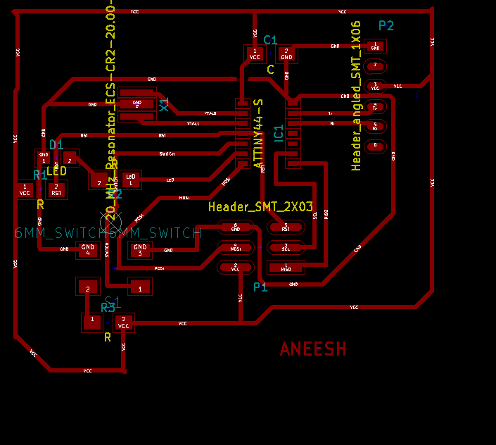
After adding the components I connected them according to the design.
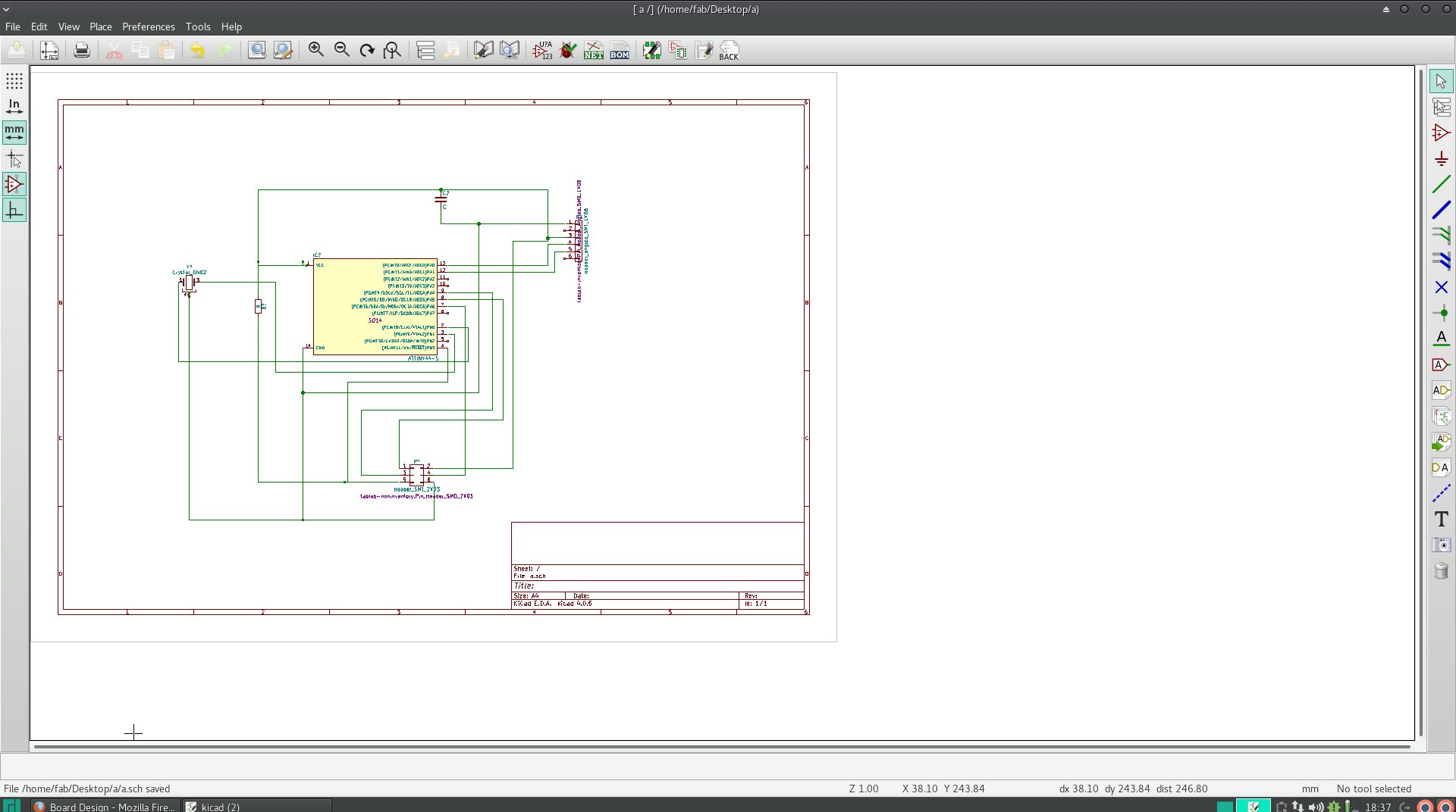
Then I annotated the components.
After this using the "Run Pcbnew to layout printed circuit board" option to route the design. This was the most difficult part of the week.
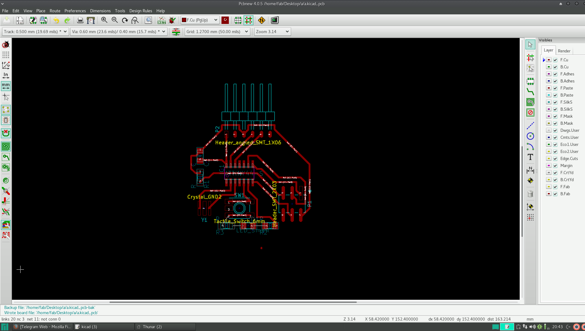
Here I used the autoroute option to route most of the routes. Had a few routes which was not routed, which I manually routed and completed it.
This had a few problem as I forgot to add ground in the initial schematic sketch. Also, connection from pin4 was wrong, which I found out only during soldering.
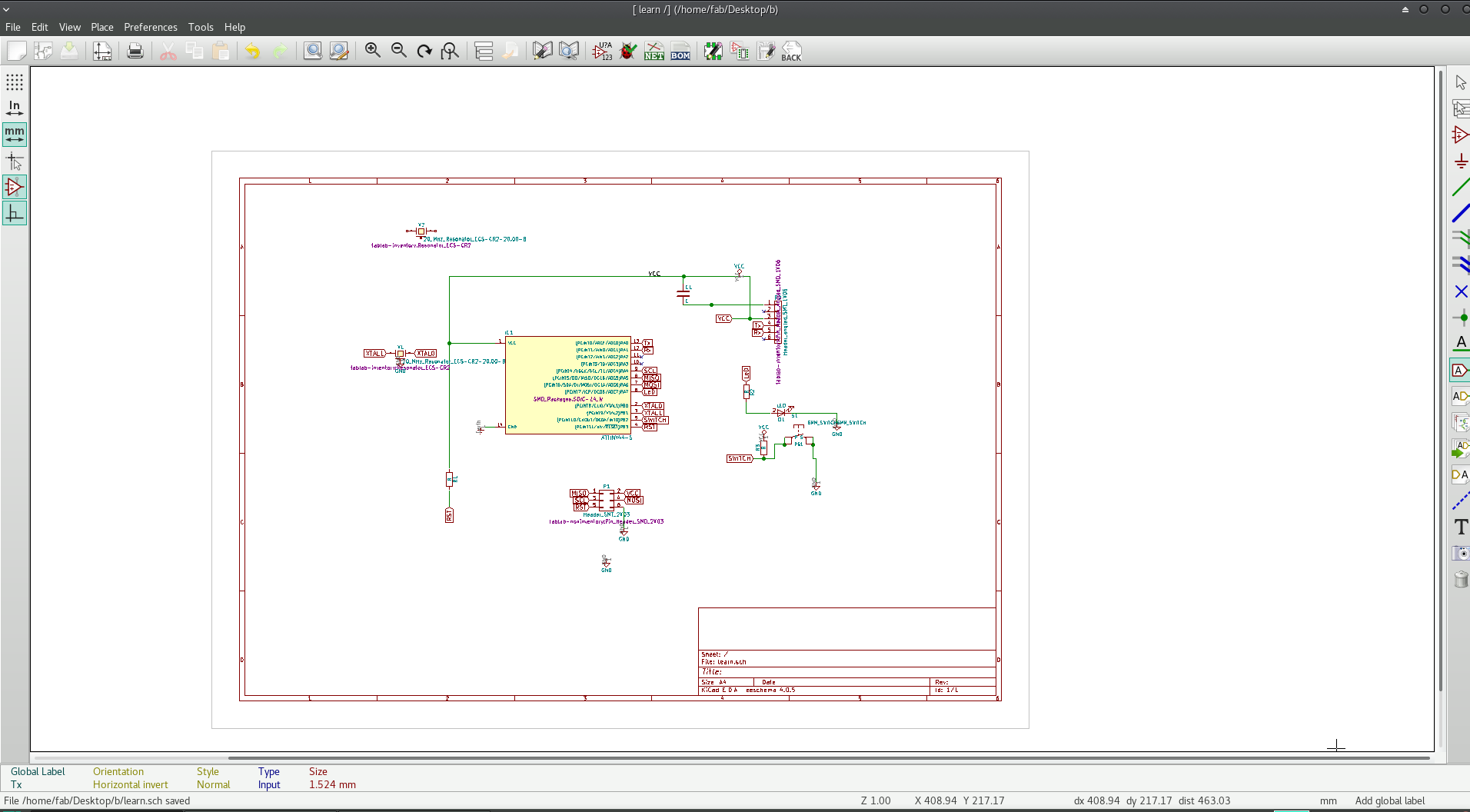
So I drew another schematic diagram, in which I gave grounding to complete the circuit.
This was very difficult to re-check, as it had too many wires. Then I came to know about "Global labelling" in KiCad. In this we can label instead of connecting the points using wire as shown in the figure below.
I added an LED with a rsistance to the 6th PIN and a press button switch to the 5th PIN of the ATtiny44.
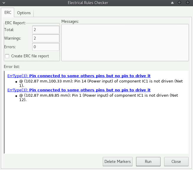
Then I performed the electrical rules check. There is a bug-like option in the toolbar for this.
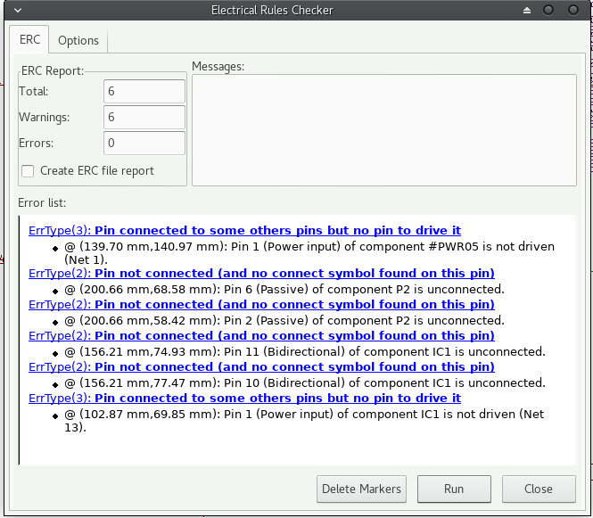
This was the result I got. This indicates the potential of Vcc is not defined and that some pins are not connected.
So I used the "place not-connect flag" option and used that in all the non connected pins as shown in the screenshot above.
After that I got the following result.
After this I routed everything manually. Worked kinda well except for two routes. So I decided to use 2 zero ohm Resistors to connect the points.
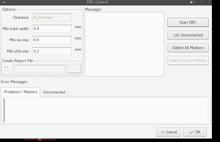
"Design rules check" was then done on the connection (again, the bug-like symbol in the toolbar is clicked).
These are the conditions I have set for checking
Min Track Width: 0.4 mm
Min Via size: 0.4 mm
We use 0.4mm because we use 1/64 bit to mill.
1/64 = 0.015625
This is in inches.
To convert to mm we multiply by 25.4 ~ i.e; 0.3969
approximately 0.4 mm.
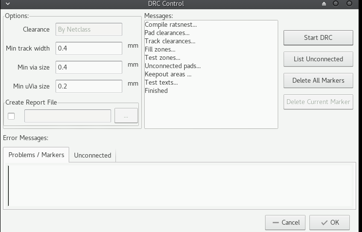
This is why we use 0.4 mm in DRC.Then I gave the "Start DRC" command
The result shows no error, hence the conditions are met, and design wise the board is good to go.
In a hurry to finish the assignment on time for regional review I used this for milling. After soldering, with the help of my instuctor Sibu, I was able to change the 2 zero ohm resistors and route it well. I had spent a whole night in routing this and I was not able to fix it. Sibu just had look at it and within seconds he solved. Hehe <embarassed>
Anyhow it was solved.
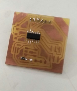
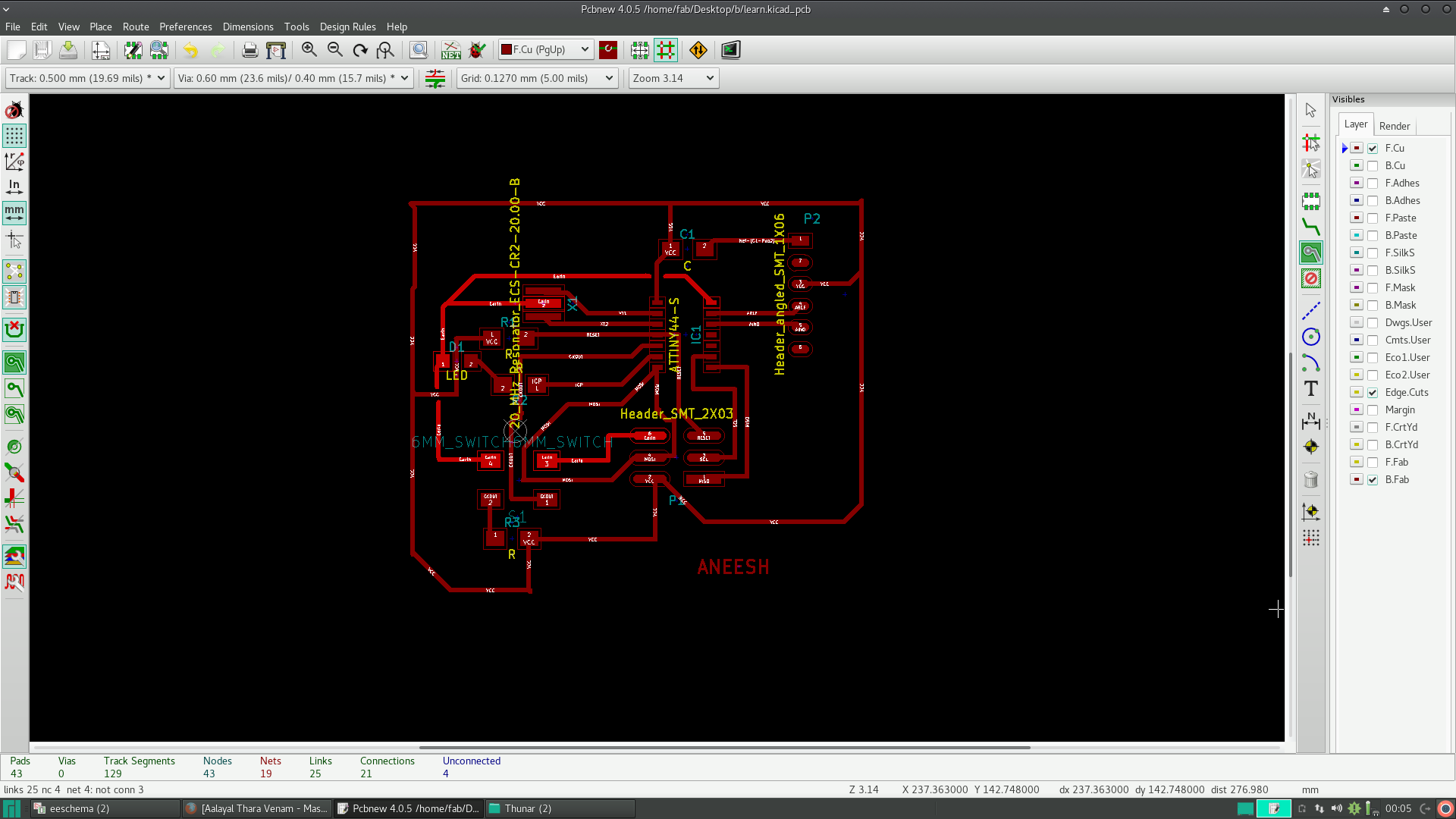
Here is the screenshot of it and the design files are attached below.
I'm planning to do this board whenever I get enough time.
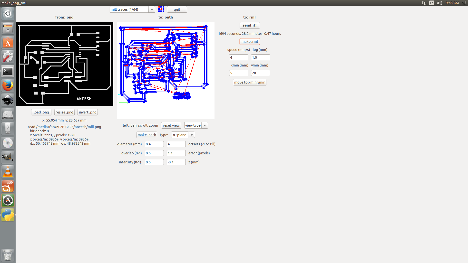
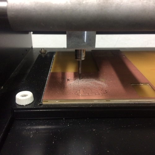
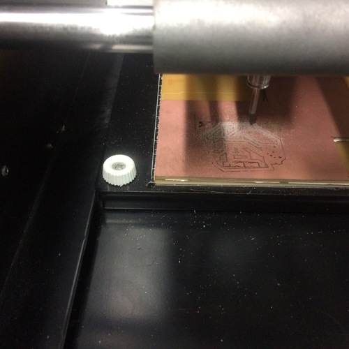
This was then converted .png format for milling.
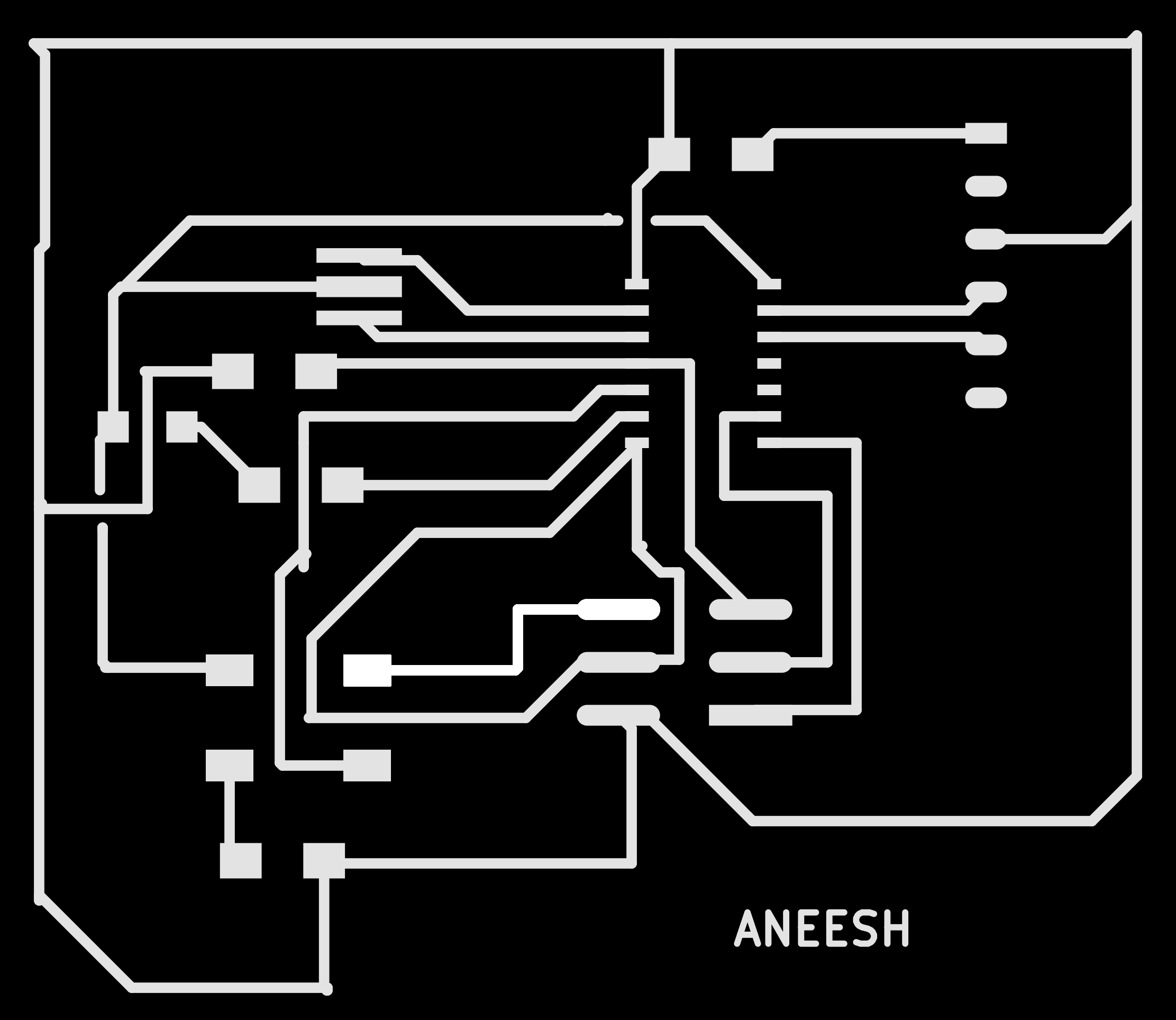
Using modella, pcb was printed.
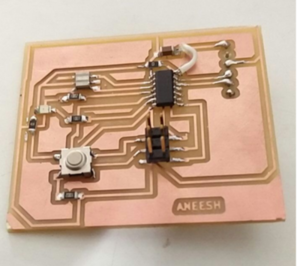
After printing the circuit I soldered the board. During soldering I found that the Capacitor was not connected to the ground. So I soldered a wire from IC - ATtiny44's ground to the unconnected end of the capacitor (as seen in the diagram).
After this, I thought I had completed everything successfully. Until I connected the board to the ISP we made 2weeks back. BOOM! There it was. I realised the horrible fact that my board is not working.
Now I've to check what the problem is with my board and if I can't find it,then I'll have to desgin a new one (SIGH!)!!!
So I checked for continuity in this board using a multimeter. Then I found that some pins were not soldered properly.
Re-soldered these pins and checked.
Now I can program the chip. Yaay! :D :P
Checking whether my ISP can detect this board
sudo dmesg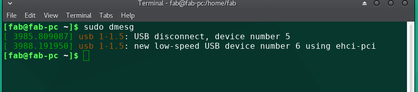
Checking if my ISP can read fuse bits from the new board I just made.
sudo avrdude -c usbtiny -b 9600 -p t44 -v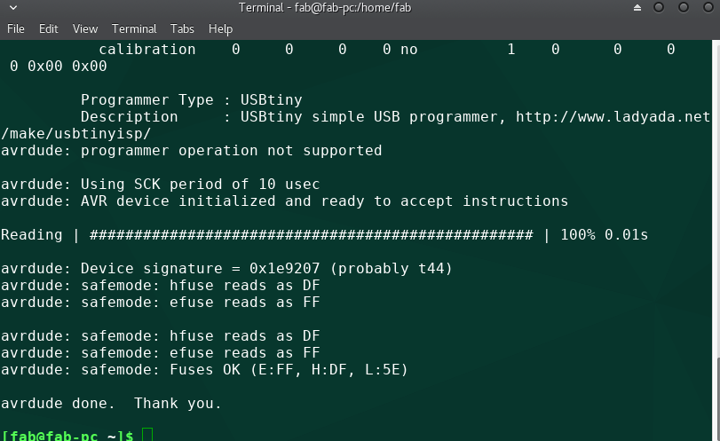
Fuse bits are readable. Now I've to flash the program.
For this I connected the board to the fabISP I made two weeks back using ribbon wire. Then downloaded the program files from fab archive and flashed the program to the board.
The following command was used to do this.
make program-usbtiny

make program-usbtiny-fuses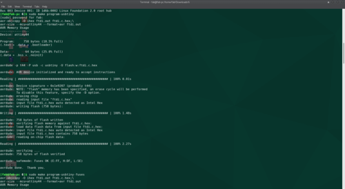
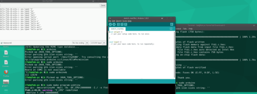
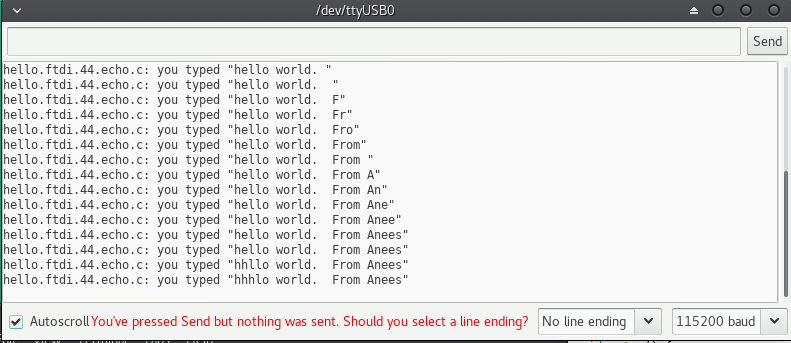
After this using 5V FTDI cable the board was connected to the PC. I used arduino IDE (integrated Development Environment) for serial communiacation.I selected the port from the tools option. Then selected "serial monitor" option from the Tools bar only. It took me to the window where the messages were displayed(as shown in the figure). Baud rate was selected as shown because that is what defined in Neil's program
After typing hello world, I tried hello world form Aneesh. But the last letter of my name didn't come through.
It really was a fun week. On friday I was the happiest man on the earth as I thought I had got my board perfect and can try other softwares from Monday. Then on monday while soldering I found out some major mistakes in my board. => Should re-check the connection after completing the schematic. SHOULD NOT BE Over-Confident.
Had to re-do the board again, which I did. But then I found Flaws in my soldering. With the help of my instructor Sibu, I was able to understand the major problems in my soldering techniques. (I'm soldering for the first time in my life). It was really interesting to know the right way to do it.
Routing was something I spent most of the time this week. Should've consulted my instructor after my manual routing, which would've helped me to NOT use the ZERO ohm resistor I used.
Overall it was an eventful and a hectic week.