[Final Project] Inventory Bot
1. Overview
What I made
I made "Invetory Bot". This is a system that can easily pick up parts and manage inventory.
- When the user inputs the part name in the search box, the head of the core XY moves to the position of the corresponding drawer, and the pin attached to the head pushes out the drawer.
- The quantity in the interface decrease at the same time as taking parts.
 Back
Back
 System overview
 Presentation movie
Why did I made this system.
I made this system in order to solve the following system.
- There are a lot of parts and it is hard to pick up.
- When sharing parts in shared space,many people forget to record use history.And sometimes there are no parts when needed.
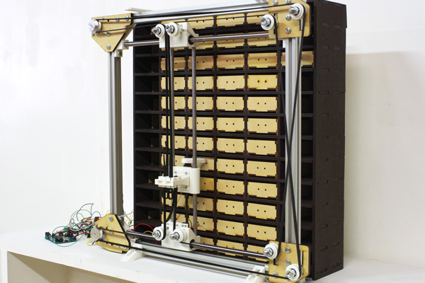
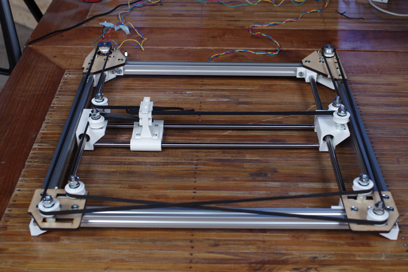
2. Mechanical design of Core XZ
Main body
At first, I made a frame of core XZ with commercially available parts.
Almminium frame
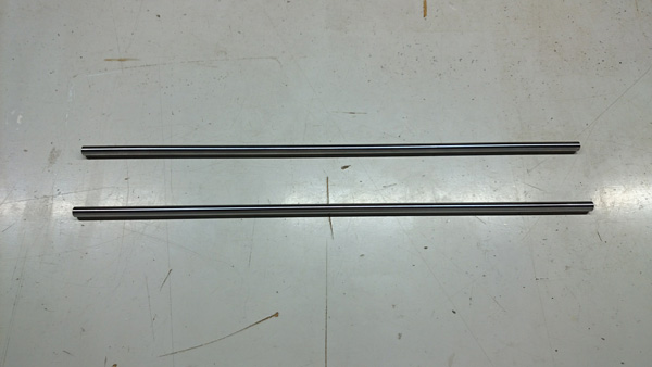
Steal shaft(SUJ2)φ8x400mm (for vertical movement)
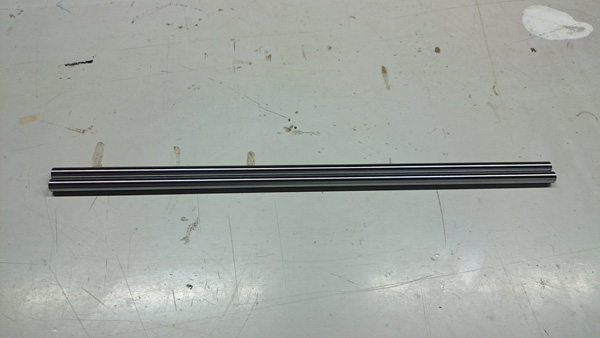
Steal shaft(SUJ2)φ10x400mm (for horizontal movement)
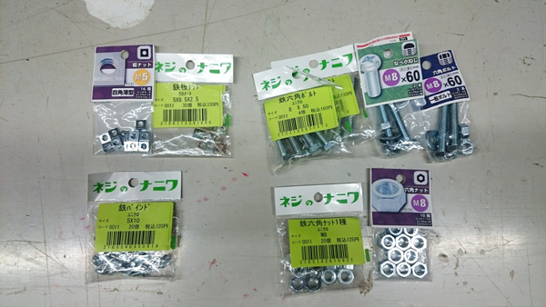
Nuts and bolts
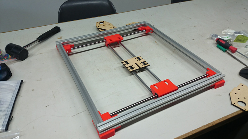
Other parts, gears and joint parts etc, were made with 3D printer or lazer cutter.
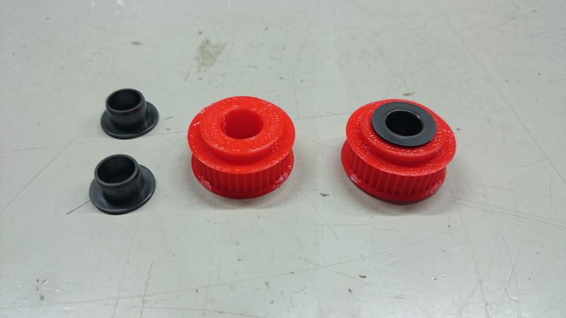
I used 3D pulley generator 'p.scad' to make GT2 pulley. This is an openscad program.
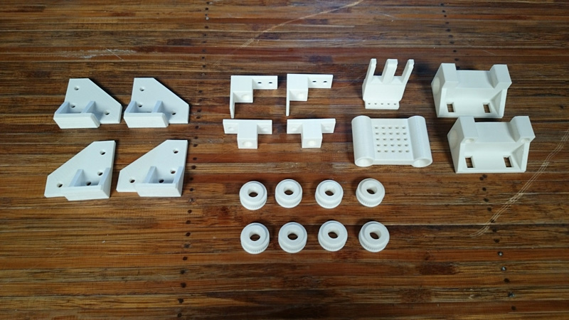
Joint and base
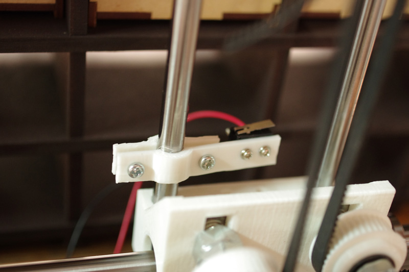
Limit swich holder.
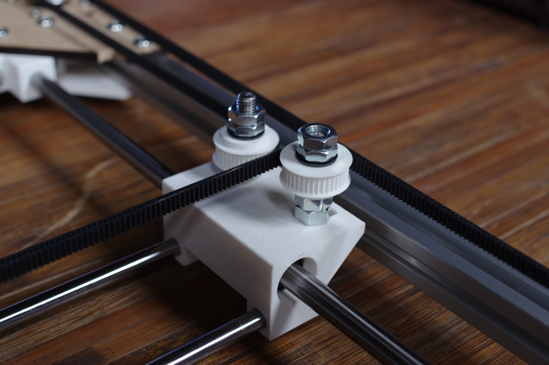
pulley and slider
Timing belt holder
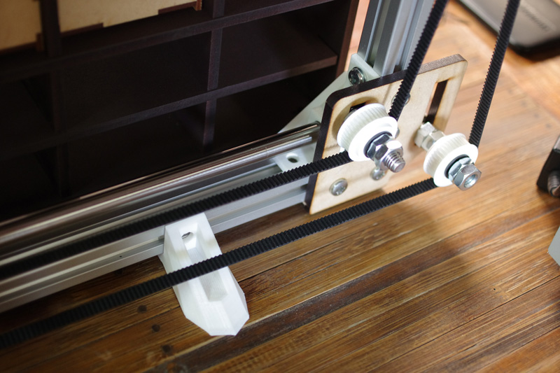
Assembled and put on a timing belt.
Download
3Ddata_coreXZ.zip: Download the file
p.scad(I used this generator to make gt2 pulley.): Download the file
2Ddata_coreXZ(almiFrame_front_3.0.ai): Download the file
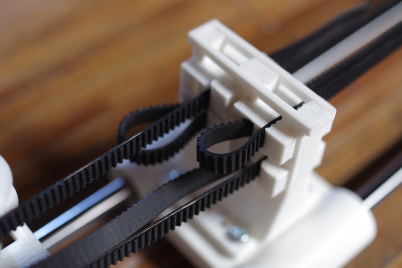
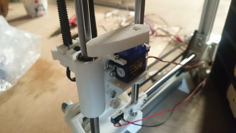
Head Part
Servo is attached to the head part of core XZ.And 3D printed part like cam is mounted on the head of the servo. When servo rotates, this part pushes out drawer from the back.
Download
cum.iges: Download the file
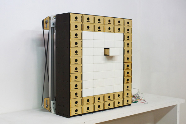
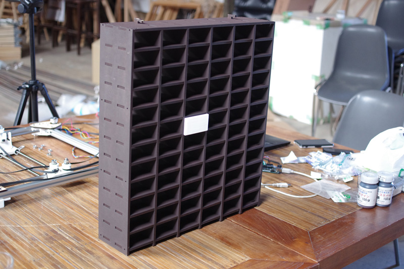
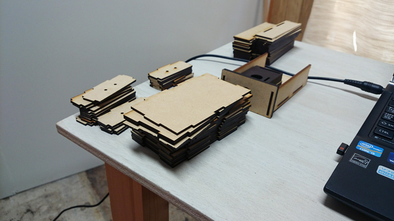
3. Design chest and drawers
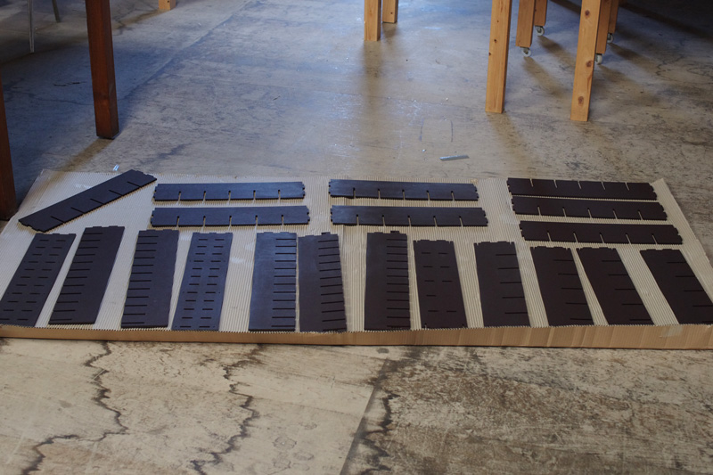
I made chest and drawers to fit core XZ. The main parts were made by lezercutter.
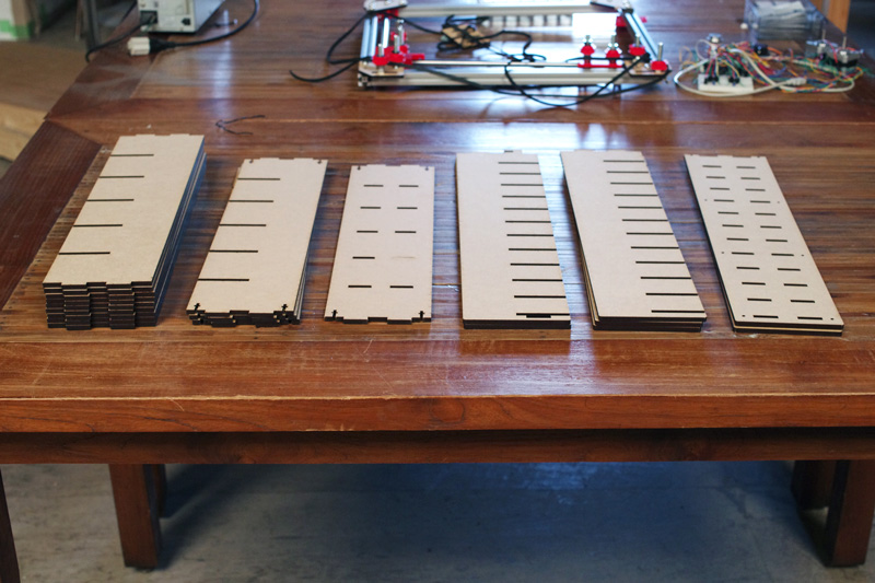
After cutting MDF, I painted it with aqueous stain.
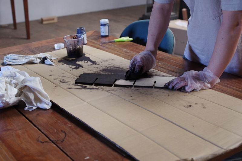
Assembled them. Because I didn't consider the thickness of the paint,the slot dimension was too tight.
The drawer was also made with a laser cutter.
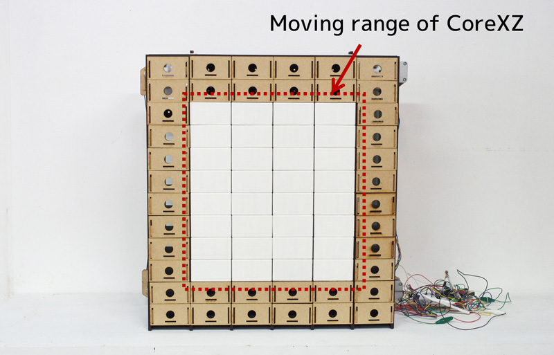
The movement range of the head is limited, so not all drawers are pushed out. Drawers other than the moving area have holes to hook your fingers, but there are no holes in other drawers. The reason for this is to ensure inventory management by preventing drawers from being opened by hand.
Download
drawers.zip(.ai): Download the file
frontPanel.iges: Download the file
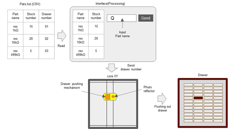
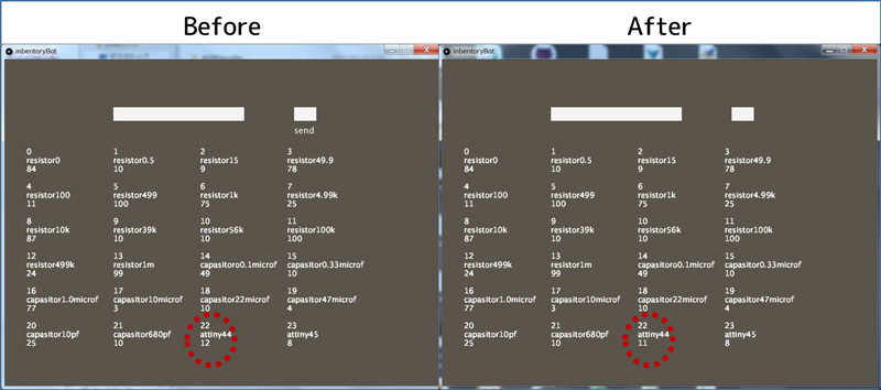
4. Interface design (include inventory management system)
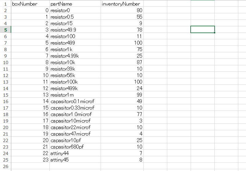
At first, I made inventory list. This list has the following columns.
- box number
- part name
- inventory number
The interface was made with processing. If the part name matches exactly, the corresponding box number is send to arduino with serial communication.
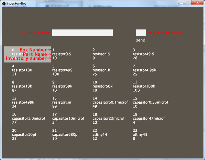
The quantity of inventory decrease at the same time as taking parts.
 inventoryBot.pde:
Download
inventoryBot.pde ( & CSV file): Download the file
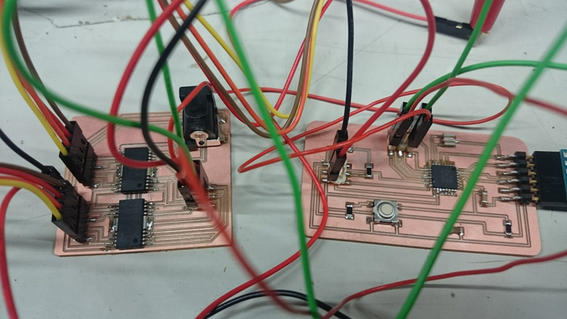
5. Circuit design
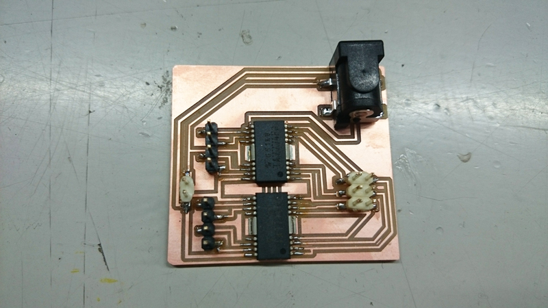
At first, I used Arduino UNO and motordriver'TB6674PG' to control devices.And then I tried to make 2 boards 'micro contoroller board' and 'motordriver board'. The reason I made them separately is because I thought that it is easy to fix the bugs. In addition when making controller board separately, it can be used for other purposes.
System
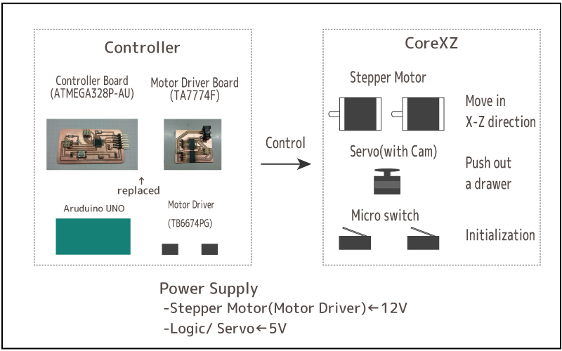
Micro Controller Board
I selected ATmega328P-AU for the controller board. When disigning schematic data, I referred to Fabduino.(External clock was 8MHz)
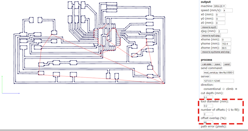
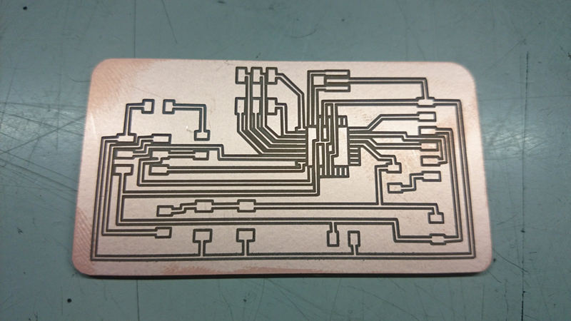
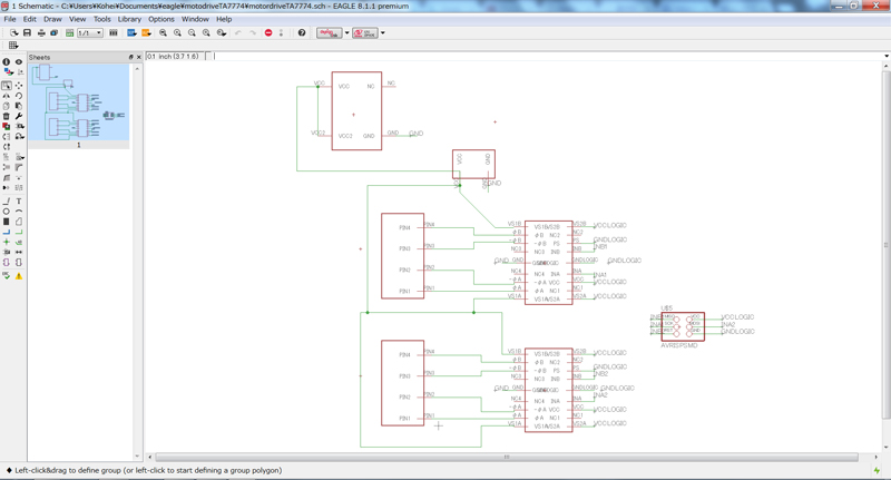
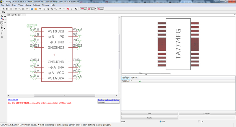
I made schematic data and board layout data with EAGLE.
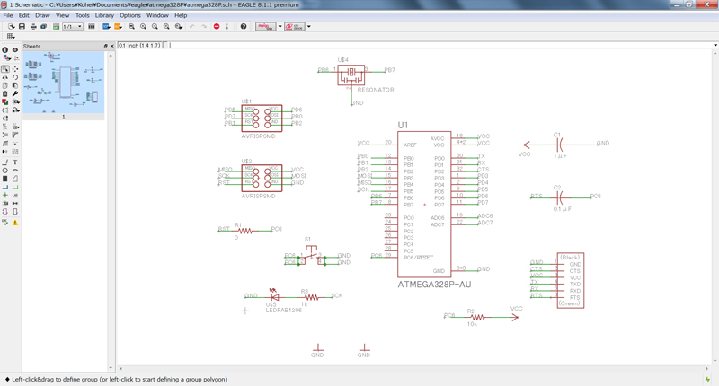
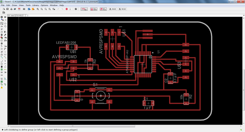
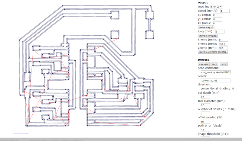
I created cut data with fabmodules. Since the interval between the pins of ATmega328P-AU is very narrow, I set the cutting conditions finely.
- tool diameter:0.2mm
- the number of offsets:2
- offsets overlap:60%
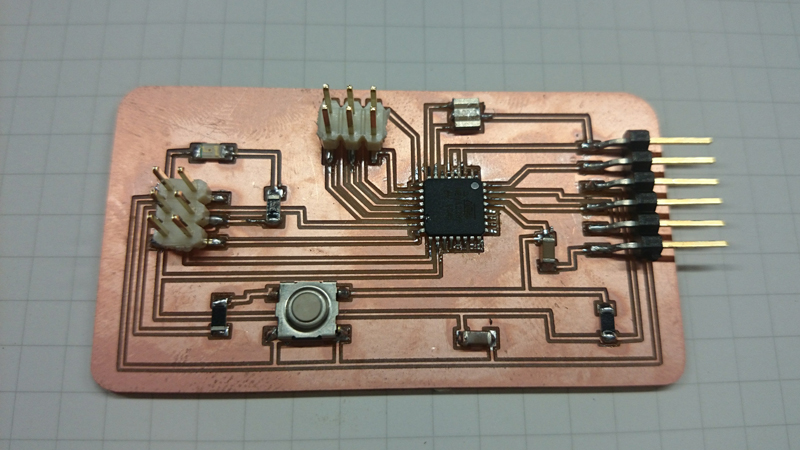
Soldering all parts
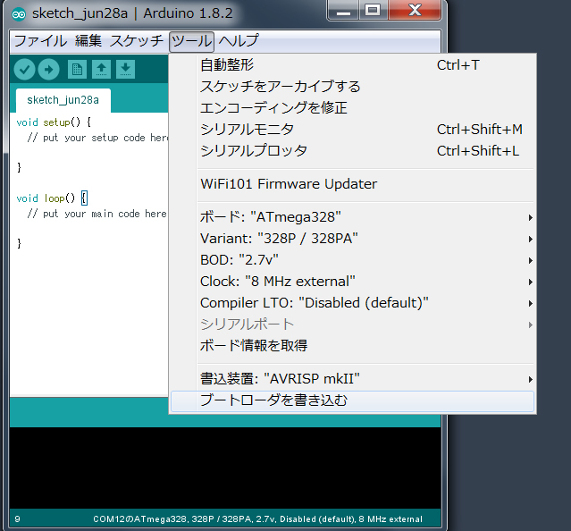
After that, I set the development environment. Add the following URL in the preference window. https://mcudude.github.io/MiniCore/package_MCUdude_MiniCore_index.json
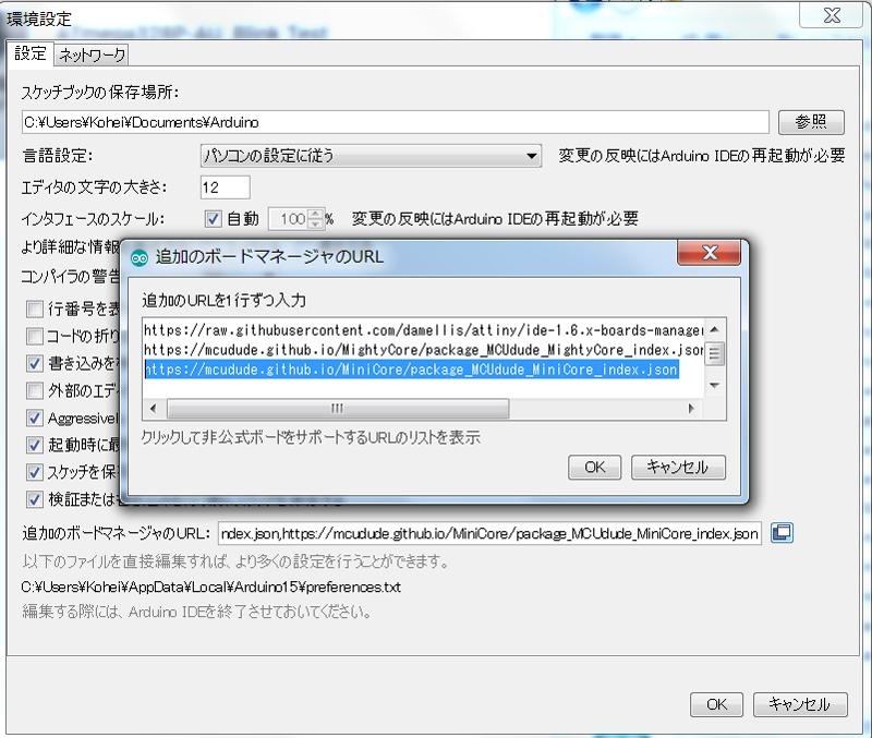
Serch and install 'MiniCore' in the board manager.
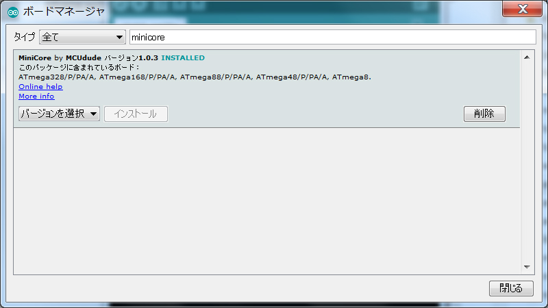
Set as follow,and burn bootloader
Motor Driver Board
Circuits for motor drive were created in the same way. I selected TA7774FG as a motor driver.This chip has the same pin assingment and similar function with TB6674PG. A jack for power supply was attached so that power could be supplied from the AC adapter.
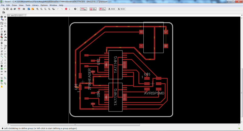
Finlly,soldering all parts
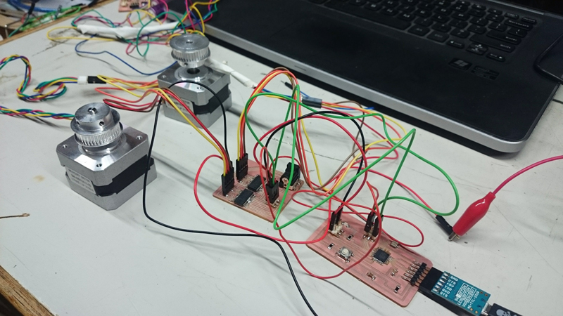
After connecting each pins I run progra. 2 stepperm motors moves as programmed.It was suceeded.So I replaced this new boards with a Arduino UNO & breadboad system.
Download
controllerBoard_atmega328P_eagle.zip (include SCH & BRD file) : Download the file
controllerBoard_atmega328P_milling.zip (include PNG file & RML file): Download the file
motodriveTA7774_eagle.zip (include SCH & BRD file) : Download the file
motordriveTA7774_milling.zip (include PNG file & RML file): Download the file
6.Programming
I wrote program with arduino IDE without using open source firmware(like marlin). I used AccelStepper library and MultiStepper class. I could control multiple motors by using them.
sketch overview is as follow.- Processing send number to arduino with serial communication.
- Based on the number, select an action by switch statement.
- At first the machine initialized.
- Currently I need to return to the origin every time, but I will make it possible to operate continuously.
Download
inventoryBot.ino: Download the file
7.Future function
When the quantities of parts become less than the specified value, the user puts black paper (signboard) on the back of the drawer. When the inventory checking operation is performed, the photo reflector mounted on the head of the core XY screen all drawers and determine the color of the back of the drawer. And then, the system notify the administrator of information on parts with low stock by e-mail.