[WEEK13] Input Device
0.Outline
What I made
I tried to measure illumination with photo transistor in this assignment.
STEP1: Studying a circuit and program to use light sensor by using Arduino UNO & sensor module. STEP2: Making two cicuit boards. I made micro processor board and photo transistor board separraterly. STEP3: Programming to the board and mesuring illumination.
1.Test on Arduino UNO
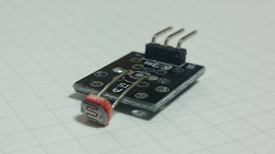
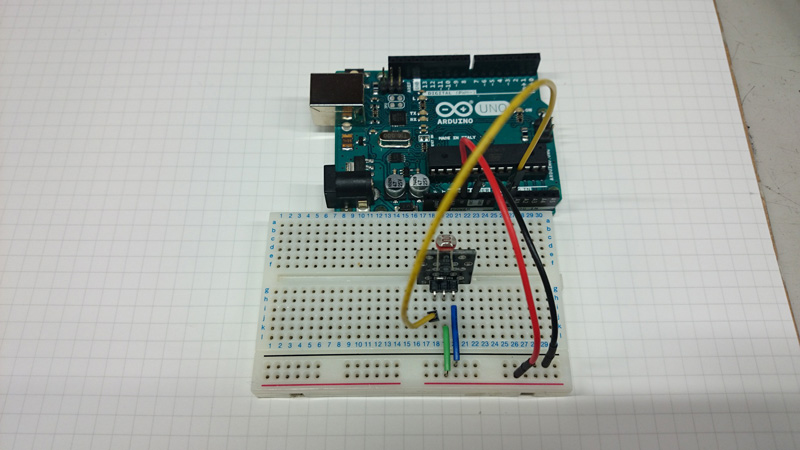
At first I used CDS sensor module and Arduino UNO for practice. This module includes CDS sensor, resistor, and pin header.
CDS sensor kit:
I conected pins and write program to read analog values of illumination and display on Serial monitor. I used map function to convert the range of maximum value and minimam value, and invert them. I studied how to use light sensor through this trial.
lightSensorTest_arduinoUNO:
2.Circuit design(Micro processor board)
2.1 Making EAGLE library
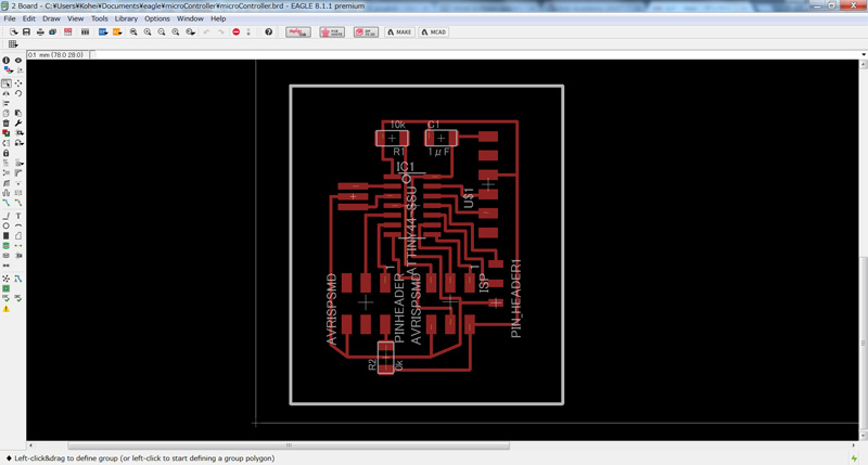
2.2 Circuit design
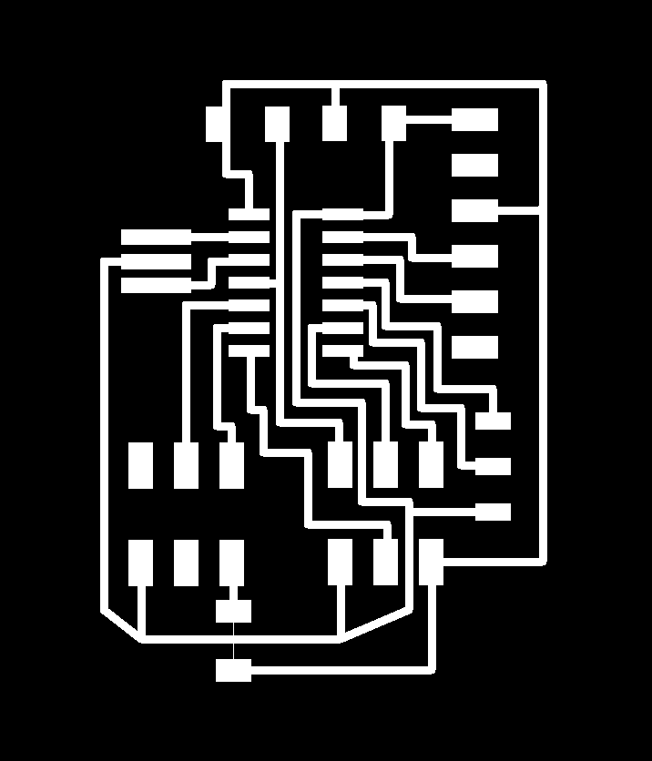
I designed circuit with EAGLE. This board was based on hello echo board. I remove the LED and button from it, and added the pin header to the vacant pin of ATTINY 44.
| Part name | P/Number | Quantity |
| ATTiny44A-SSU | 1 | |
| Capacitor 1uF | 1 | |
| Resistor 10K ohm | 2 | |
| 20MHz Resonator | 1 | |
| 6-pin programming header | 2 | |
| FTDI header | 1 | |
| 3-pin header | 1 |

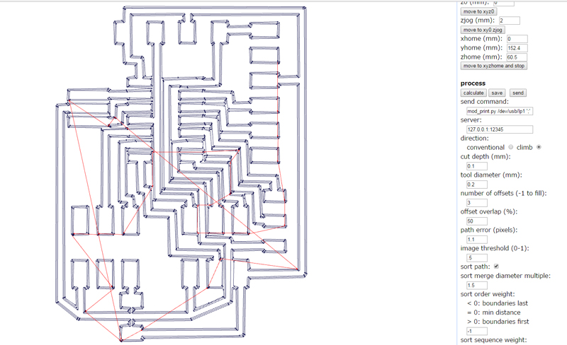
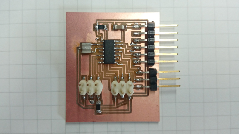
2.3 Maiking Circuit board
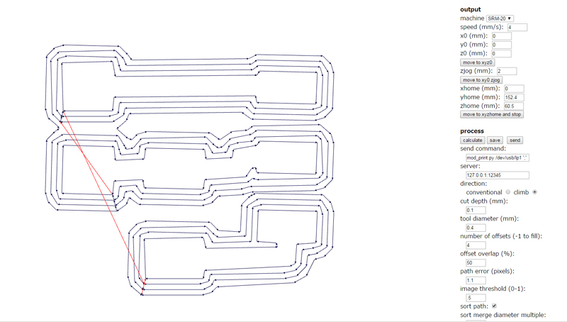
I created tool path data with Fabmodules and milled circuit board with SRM-20. And then, I soldered all parts.
dpi:500 cut depth (mm): 0.1 tool diameter (mm): 0.2 number of offsets: 3 offset overlap (%): 50

Download
microController.sch: Download the file
microController.brd: Download the file
microControllerBoard_trace.png: Download the file
microControllerBoard_outline.png: Download the file
microControllerBoard_trace.rml: Download the file
microControllerBoard_outline.rml: Download the file
3.Circuit design(Light sensor board)
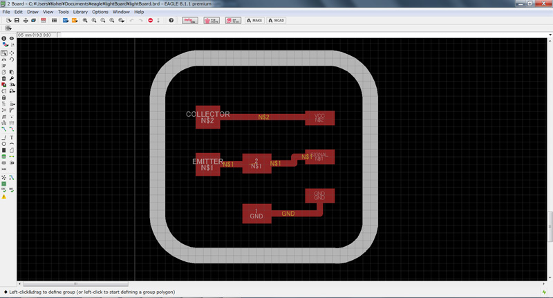
3.1 Circuit design
I used photo transistor to mesuring illuminance. The circuit diagram is as follows. In order to prevent an excessive current, it required at least 250 ohms of resistance.Since I only had 499 ohm resistance at hand, I used it.| Part name | P/Number | Quantity |
| Photo transistor | PT15-21C/TR8 | 1 |
| Resistor 499K ohm | 1 | |
| 3-pin header | 1 |

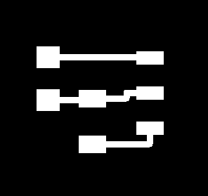
In the same way as before, drawing a circuit diagram with EAGLE and creating png data for milling.

3.2 Maiking Circuit board
I used Fabmodules and SRM-20 just like above. And then I soldered all parts.
dpi:500 cut depth (mm): 0.1 tool diameter (mm): 0.4 number of offsets: 4 offset overlap (%): 50


Download
lightBoard.sch: Download the file
lightBoard.brd: Download the file
lightBoard_trace.png: Download the file
lightBoard_outline.png: Download the file
lightBoard_trace.rml: Download the file
lightBoard_outline.rml: Download the file
4.Programming
At first, I tried to program .c file (hello.light.45.c) with makefile. But it was failed. When I did meke clean command, the following message was shown. I couldn't fix this bug. So I decided to write a program using arduino IDE. After burning bootloader on ATTINY44 and proram the following sketch. The workflow is described in assignment 8
Download
lightSensorTest.ino: Download the file
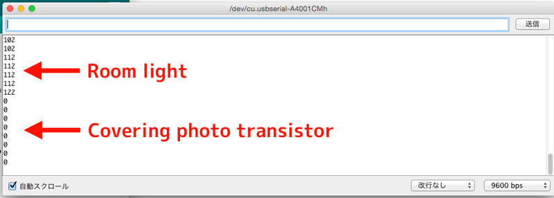
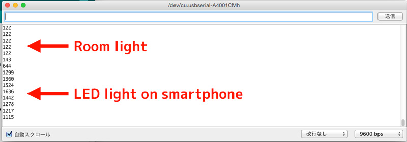
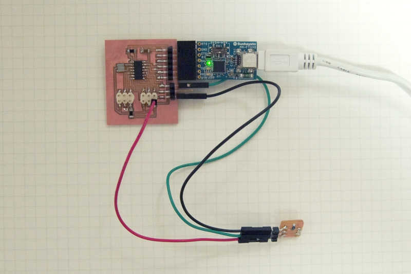
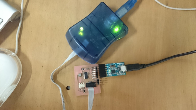
After programing, I took off the programmer(AVRISP mk2) and connected the photo transistor board. When opening the serial monitor, the sensor value was displayed.
When illuminating the phototransistor or covering it by hand, it changed in response to it.