[WEEK10] Output device
0. Overview

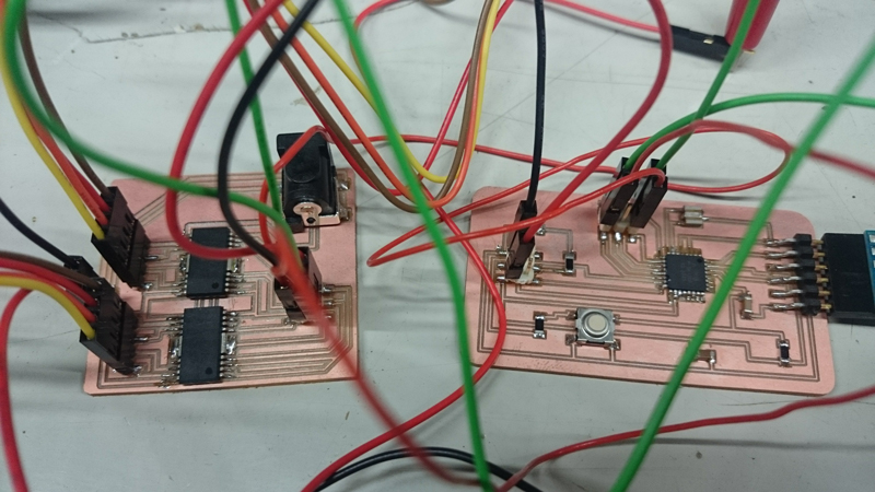
I made a 2 circuit boards. The one is to contorol 2 stepper motors and the other is to control servo. The former was succeeded ,but the latter wasn't.
1. Making circuit board for 2 bipolar stepper motors
I tried to make 2 boards 'micro contoroller board' and 'motordriver board' . The reason I made them separately is because I thought that it is easy to fix the bugs. In addition when making controller board separately, it can be used for other purposes.1.1Micro Controller Board
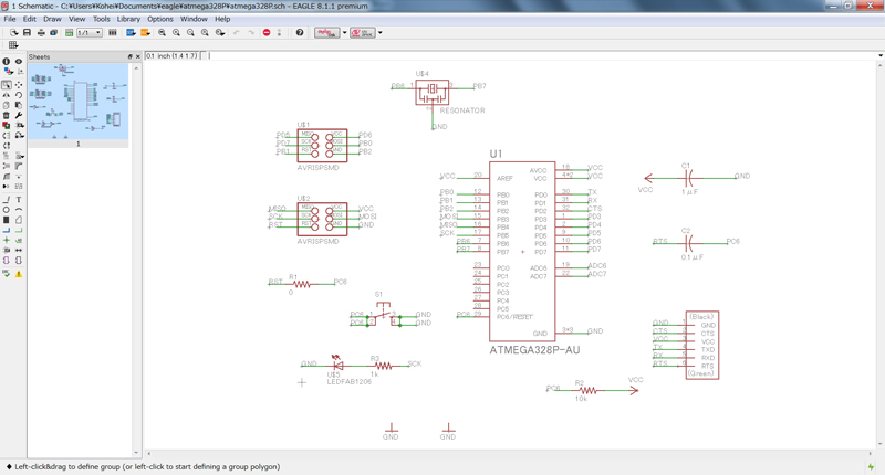
I selected ATmega328P-AU for the controller board. When disigning schematic data, I referred to Fabduino.(External clock was 8MHz)
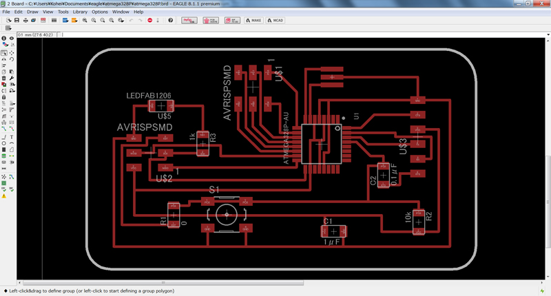
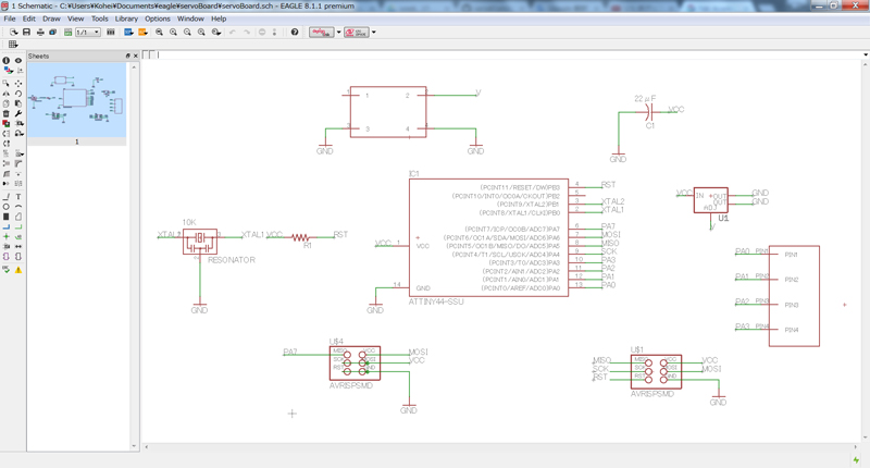
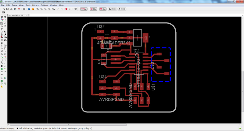
I made schematic data and board layout data with EAGLE.
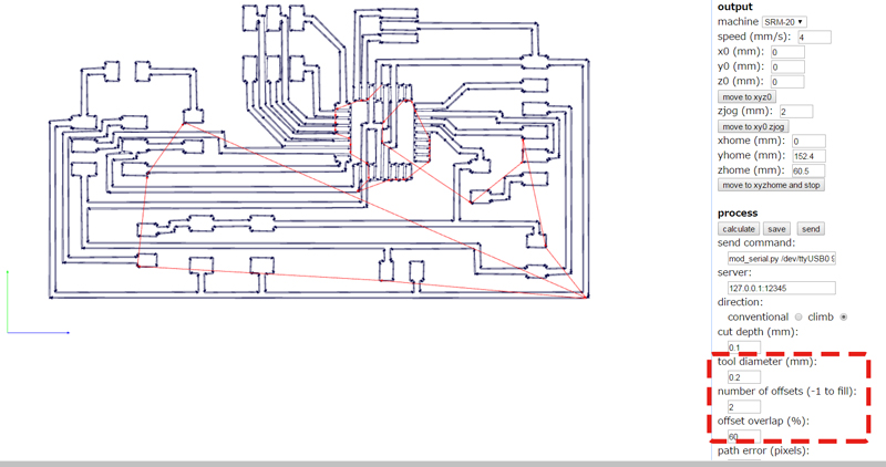
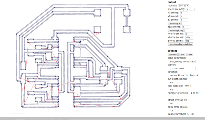
I created cut data with fabmodules. Since the interval between the pins of ATmega328P-AU is very narrow, I set the cutting conditions finely.
- tool diameter:0.2mm
- the number of offsets:2
- offsets overlap:60%
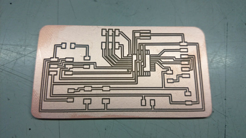
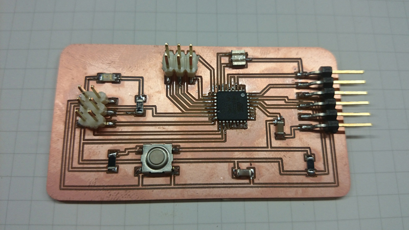
Soldering all parts
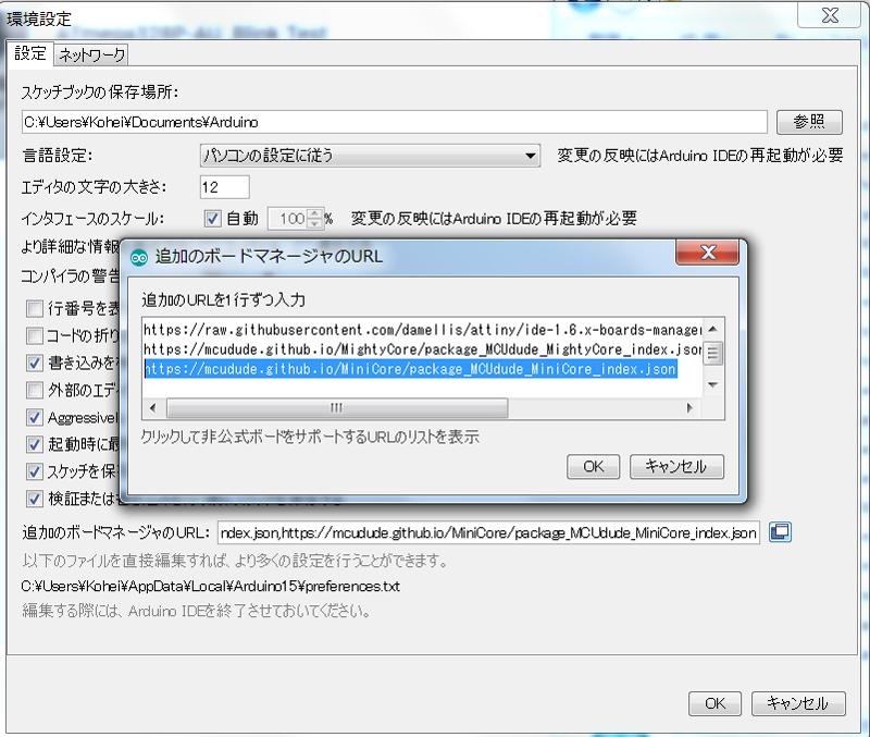
After that, I set the development environment. Add the following URL in the preference window. https://mcudude.github.io/MiniCore/package_MCUdude_MiniCore_index.json
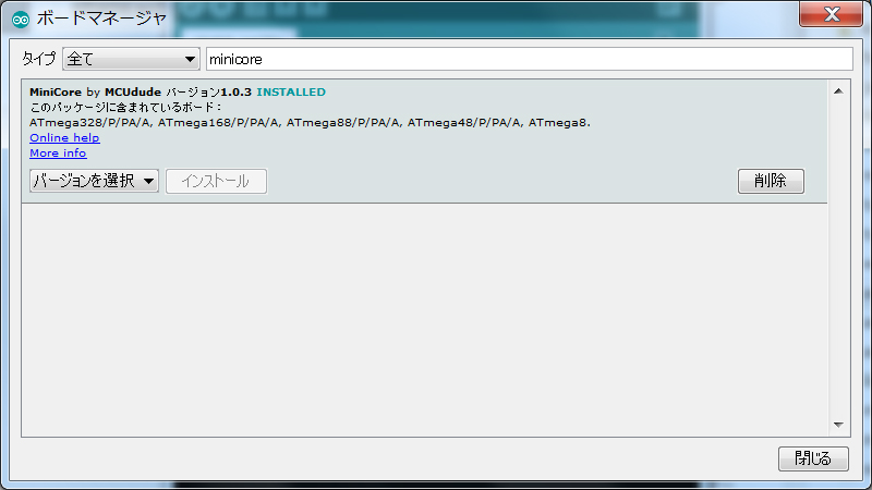
Serch and install 'MiniCore' in the board manager.
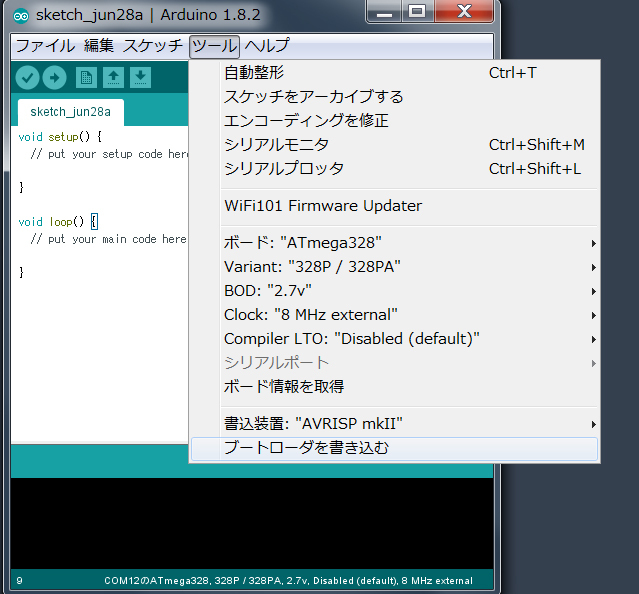
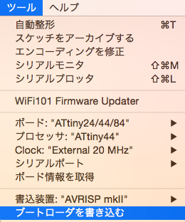
Set as follow,and burn bootloader
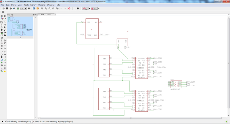
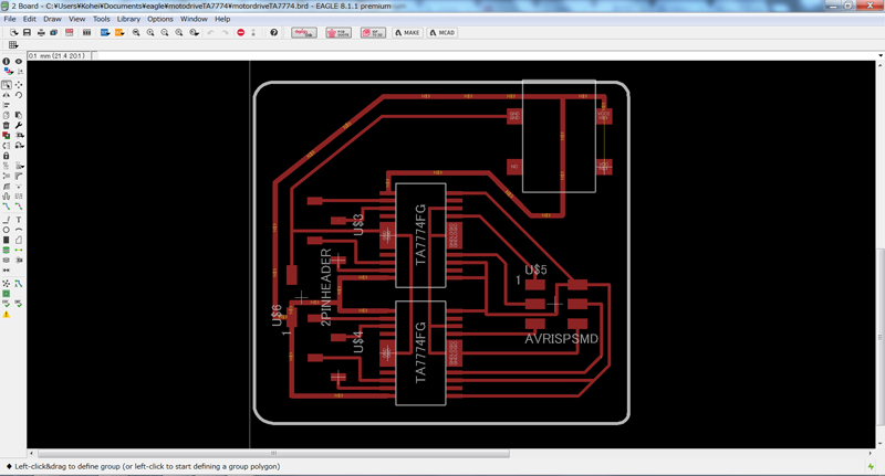
1.2 Motor Driver Board
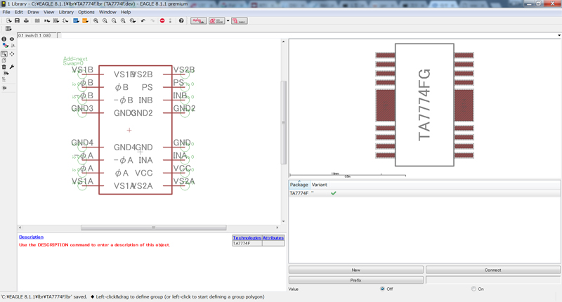
Circuits for motor drive were created in the same way. I selected TA7774FG as a motor driver. A jack for power supply was attached so that power could be supplied from the AC adapter.
!!Additional comment after feedback!!
I used TA7774FG instead of Fabinventory because...
- I was worried about breaking the driver because it was my first time to use a motor driver to control a stepper motor.
- So I wanted to test with a dip type device and bread board.There was a dip type device(TB6674PG) with almost the same specification as the TA7774FG.
- And I wanted to use a part that I could buy at the local shop.Even If it gets broken, it will be available immediately at a cheaper shipping cost.
- TA7774FG has a simple pin layout. So I thought that if I could use it, I could make a circuit that is simpler and more efficient than using the parts of the Fabinventory.
- As a result of testing, I was able to satisfy the requirements with the specification of TA7774. So I used it as it was.
Finlly,soldering all parts
I wrote program as follow.
- Input ’1’ into the serialmonitor 2 stepper motors moves.
- I used AccelStepper library and MultiStepper class. I could control multiple motors by using them.
After connecting each pins I run progra. 2 stepperm motors moves as programmed.It was suceeded.So I replaced this new boards with a Arduino UNO & breadboad system.
Download
controllerBoard_atmega328P_eagle.zip (include SCH & BRD file) : Download the file
contorllerBoard_atmega328P_milling.zip (include PNG file & RML file): Download the file
motodriveTA7774_eagle.zip (include SCH & BRD file): Download the file
motordriveTA7774_milling.zip (include PNG file & RML file): Download the file
stepperControl_ATmega328P.ino Download the file
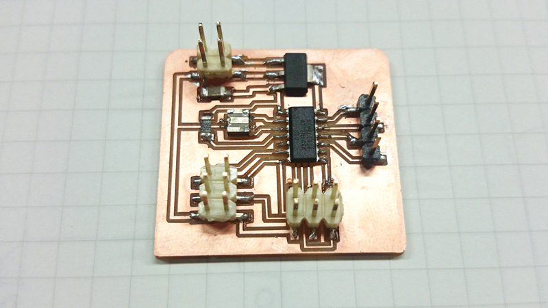
Making circuit board for Servo
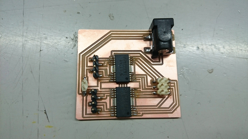
I designed circuit board to move servo reffering to the sample circuit. I added some pins on it to use in many ways.
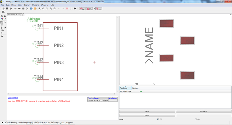
Since there was no data of pins that I had, I created a new library.
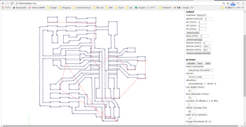
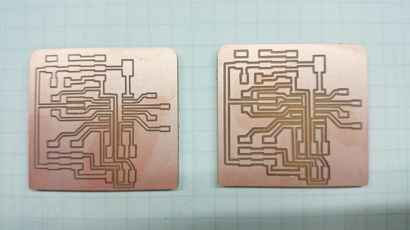
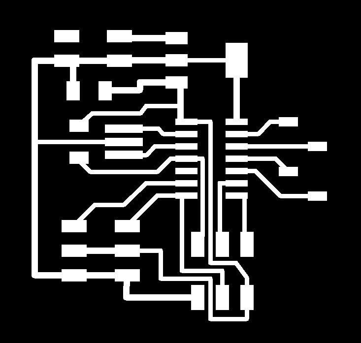
Create cut data with fab modules. There were some thin passes in this data, I reduced the number of offsets for the test. The results when the number of offsets was set to 2 and 3 are as follows.(I usually set 3 or 4)
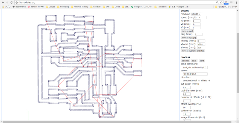
Even 3 times did not have any problem. So I adopted it.
Finally, I soldered all parts.
Download
servoBoard eagle project file.zip (include servoBoard.sch & servoBoard.brd ): Download the file
servoBoard_trace.png: Download the file
servoBoard_interior.png: Download the file
servoBoard_trace.rml: Download the file
servoBoard_interior.rml: Download the file
2. Programming
At first, I burned bootloader on ATtyny44.
And then,I programmed a simple sketch to check the operation.
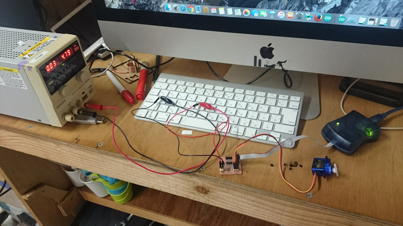
servoTest.ino:But a servo didn't move. Boot loader burning and sketch writing seemed to be successful.
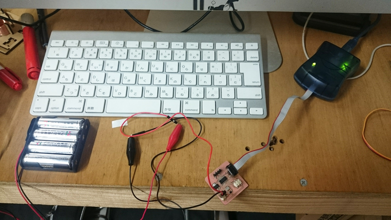
I changed the power supply from the battery to the stabilized power supply, but it did not move.
Download
servoTest.ino: Download the file
3. What I checked
Eventually I could not solve the problem. what I confirmed is described below for bug fixes.
- Whether the circuit is wrong.
- Whether the circuit is short-circuited or no. I checked all terrminal and area with electric tester.
- Soldering problem. I think this is the most probable, because the light of AVRISPmk2 was sometimes flashing.So I tried resoldering the dirty area but it did not work out.
- Check the voltage between power supply and ground terminal of servo.
- Am I mistaking the pin number? I checked datasheet of attiny.
- whether the servo was broken. I run the same program on the arduino UNO. Then servo moved.So the servo isn't broken and the program inn't wrong.