COMPUTER CONTROLLED MACHINING
ASSIGNMENT
Make something big.
DESIGN OF BED-SIDE TABLE/STOOL
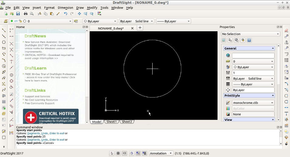
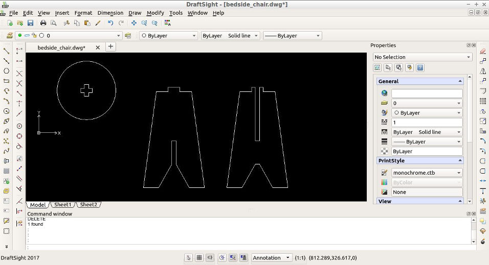
Draftsight is used to design a bed-side table that can also be used as a stool. First, draw a circle and a cross in the middle, which will later become the slot for the legs of the bed-side table.
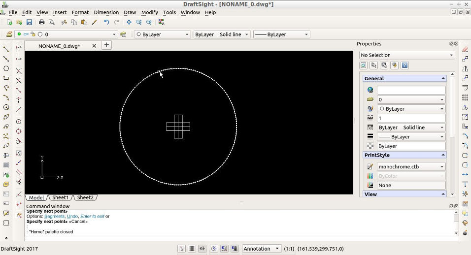
Draw the rest of the lines for the slot, carefully measuring according to the thickness of the material to be used.
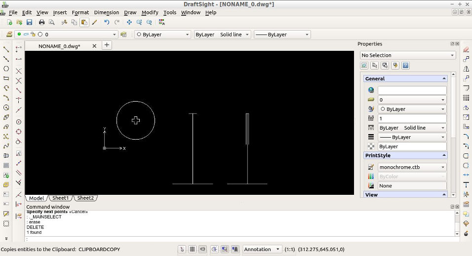
Outline the skeleton for the legs, the idea is for them to press-fit too.
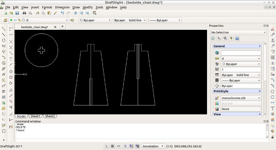
Draw the outline for the legs. Draftsight has a nice feature to snap to the symmetric points.
Using the 'trim' tool, get rid of the unnecessary lines in the drawing. Also, double-check the dimensions.
The design is almost ready, now it is important to take into account the tool tip of the CNC machine. As it is round, 90 degree angles in the t-slot must account for the tool-tip. For the round table, curved lines are added with a radius of 3.3mm with the circle and trim tools.

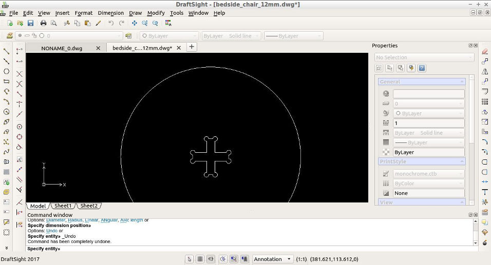
THe same is done with the rest of the slots in the legs.

TESTING OF JOINTS
Fusion 360 is used to test that the design fits together.
First, design is imported into the workspace as DXF
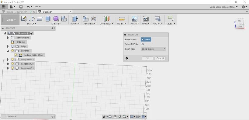
The design will be imported as a new sketch.
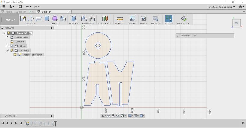
Next, extrude the designs with e hotkey to desired thickness.

Transform the bodies into components. This will allow to use the join feature of Fusion 360.
Press the j hotkey to bring the 'joint' toolbox. Select one by one, the component 1 and component 2 joints.
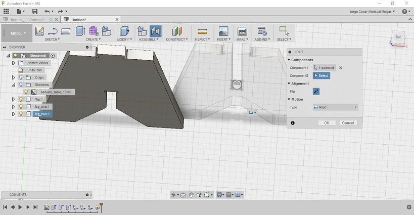
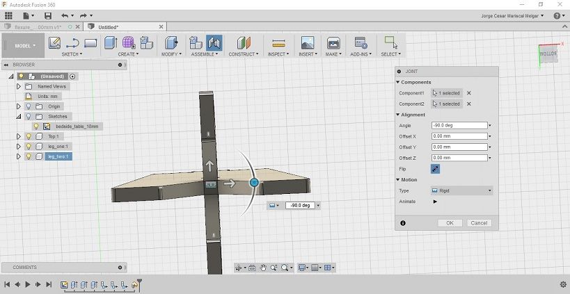
The components will join automatically. If necessary, it will be needed to specify the angle.
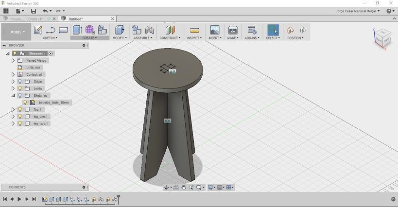
Do the same with the top; if it fits, there would not be any apparent interference.
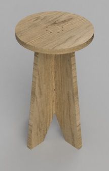
A render image of the design can be also created with Fusion 360 in the render workspace.
MILLING OF THE DESIGN
The CNC machine in the Fab-lab is the Easy Worker MasterPro 2513 which operates with a rack and pinion drive operating at a maximum speed of 19,000 mm/min. The machine features a vacuum table and an automated changing system. The working area is of (2600 x 1400 x 300) mm.

The machine uses a proprietary software, elsign CNC which opens dxf files in R12 format and transforms the image to the data format supported by the machine, G-Code or HPGL.
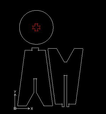
In order to get the design ready for milling, the outlines are color coded according to the order in which they will be cut in Draftsight.
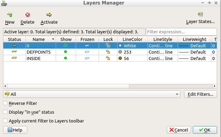
In this case, there is only one inner cut, coloured red.
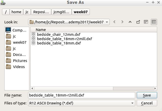
Next the file is saved as dxf R12 format.
The same procedure can be done with Rhino.
Next, prepare the material.
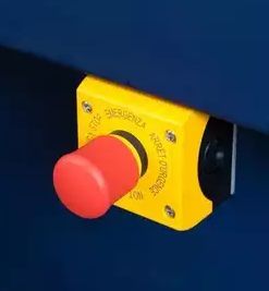
I will be using 18mm plywood to cut the design. The stock material is measured from both ends carefully and layed out on the machine bed. The Easyworker has a vacuum table which is operated according to the location of the stock material. The indicator signals are located in front of the machine:

After activating the appropriate vacuum pump positions and doublechecking that the stock material does not move, it is time to import the DXF file into the machine's proprietary software.
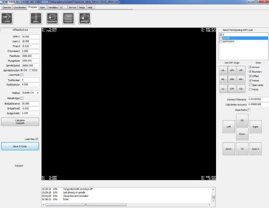
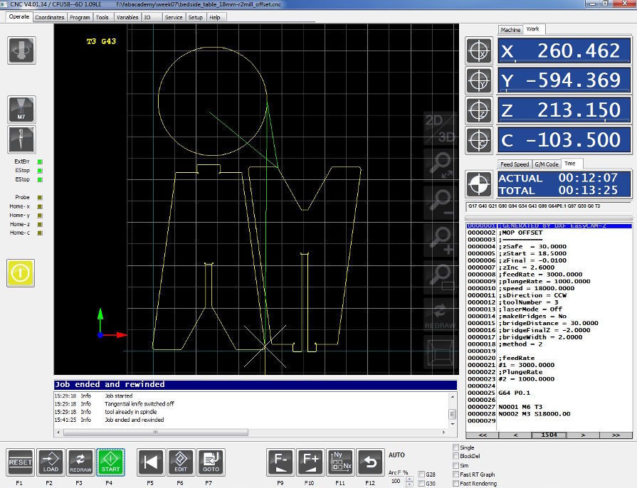
Elsign CNC's software UI's operation and program tabs look like this:

The starting coordinates for the cut are set. The origin is at the bottom-right corner of the machine.
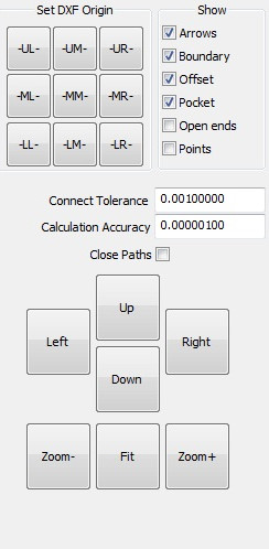
In Elsign, the position of the milling head is moved in tab-automatic. The milling head is moved using the keyboard arrow keys or the machine hardware remote controller. The coordinates are set by clicking on the button illustrated below:

Next, it is necessary to align the machine to the objects to be cut. Select LL (lower left) to make sure the machine starts to mill at the lowest leftmost point in your drawing.
The program settings are set:
For material thickness of 18mm:
-------------------------------
Safe-Z = 30
Start-Z = 18.5
Final-Z = -0.010
Z-increment = 2.6
Feed Rate = 3000
Plunge Rate = 1000
Spindle Speed = 18000
Spindle Direction = CW
Tool Number: 3
Tool Diametre: 4
Method: Inner CW for inner cut and Outside CW for outer cut.
Bridge Distance: 30
Bridge Final
The final-Z is negative because it will cut through the material and also a bit of the protective base sheet.
As for the the Z-increment, it is about half of the tool diameter.
The feed rate determines the removal rate, it is the surface speed at the centre of the tool. It depends on the type of surface to be cut and can have an effect on the roughness profile of the finished surface..
Spindle speed is related to the feed-rate, it is the rotational speed of the cutting tool. A high value for this parameter will generate more heat.
If the tip gets too hot, a good rule of thumb is to increase the feed rate or decrease the spindle speed. If the quality of the edge cut is wavy, it is tool chatter and the feed rate should be decreased or spindle rate increased.
Some useful formulas are found here. The feed rate can be calculated with the following formula:
$$\textrm{Feed Rate}= \textrm{RPM} * \textrm{Chip Load} * \textrm{Number of Flutes}$$
In Elsign software, in order to cut the inner-cut of the design, the layer 'inside' is selected in the program panel.
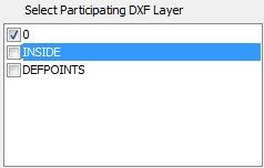
It is important to check which type of toolpath is selected. The method for the inner cut is Outside CW (counter-clockwise).
After all parameters are double-checked. Click on calculate tool path, save the G-code and the software will change the UI to automatic mode.
The Milling process is ready to start for the inner traces. Double check the maximum z-height of the machine, turn on the dust extraction system and make sure that the stock piece does not move and the vacuum bed works.
To start the job, f4 must be pressed. It is good practice to be ready to press the emergency button in case anything unusual happens.
The milling process for the inner-cut completed successfully.
Video: Milling the inner-cut [ File size: 1.1Mb]
The next step is to do the outer cut, the step to follow are the same. The appropriate DXF layer is selected and the path is calculated before launching the job.

The job is launched following the precaution procedures and the milling process is followed carefully. The software estimates the cutting time in the operation tab.
The final cut pieces looked as follows:

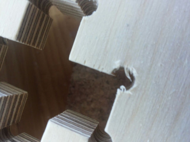
A close-up to the joint, it was necessary to sand everything to smooth it out.
After sanding, the semi-assembled piece looked like this:

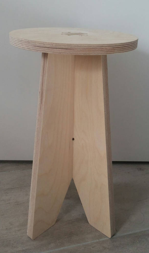
The final piece:
Observation: the top piece of the design could only be inserted from one side only. It is probably because there was some woobling in the tool while cutting.
DESIGN OF FLEXURE PATTERN
I wanted to design from scratch flexure/kerf outlines for a bendable model of a cilindrically-shaped storage furniture for umbrellas or other items.
Fusion 360's sketching tools are parametric, it provides the necessary flexibility to modify the design on the go.
First start by designing the outline of the cut using constraints from the 'sketch palette'.
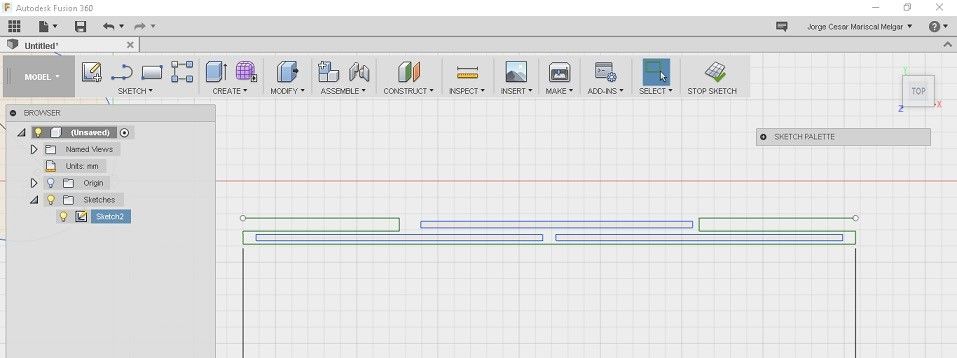
Next, insert the appropriate dimension constraints to the design through the model menu or by using the d hotkey.

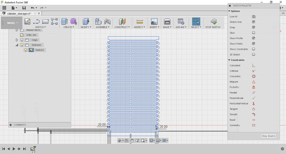
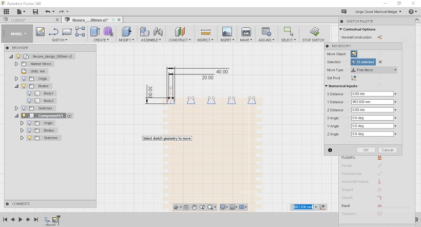
Use the rectangular pattern tool to populate the design with the pattern. Select 'Spacing' as distance type and choose 'One direction' and the desired quantityof objects to be cloned vertically. In this case, the height of the original drawing is 40mm, so the distance for the vertical pattern is also 40mm.
I want to have the design to be able to wrap around a circle with diameter of approximately 30cm, so for that I added 23 copies of the design in upward direction.
As $23 * 40 \textrm{mm} = 920 \textrm{mm}$ and $\frac{920 \textrm{mm}}{\pi}=292\textrm{mm}$, the pattern will wrap around a base of approximately 30cm diameter.

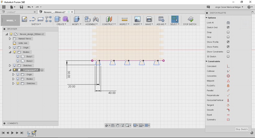
Next, the upper and lower part of the design are closed and the design is made a bit narrower. Now the design will wrap around a circle of appoximately 30.5cm.
INCORPORATING FLEXURE PATTERN IN DESIGN
The design idea is a hollow cylinder for storage of items, such as umbrellas.
Start by designing dovetail joints. Create a new sketch and use construction lines and constraints to design the first pattern.
Next, similarly to how the flexure pattern was created, create a rectangular pattern in horizontal direction.
Repeat the procedure at the bottom of the design, make sure to align the dovetails with horizontal/vertical constraints
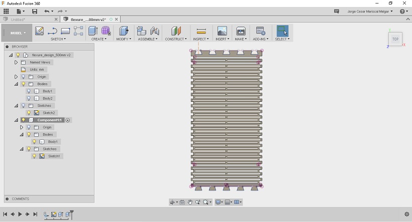
Extruded design looks as follows:
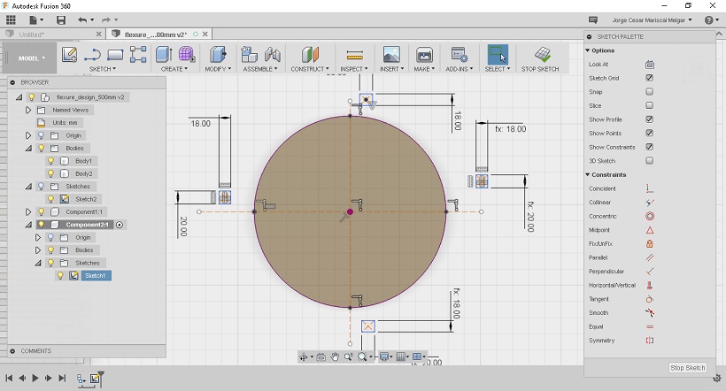
Next, create the base. The circumference of the circle must correspond to the height of the flexure body. Extrude the part.
Next, create 4 squares in a new sketch and constraint accordingly.
Finish the sketch by adding respective design choices.

Next, add 2 concentric circles matching the slots.
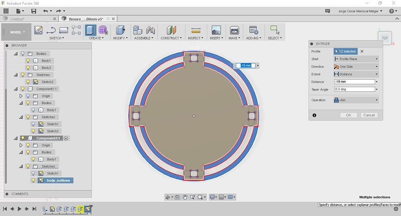
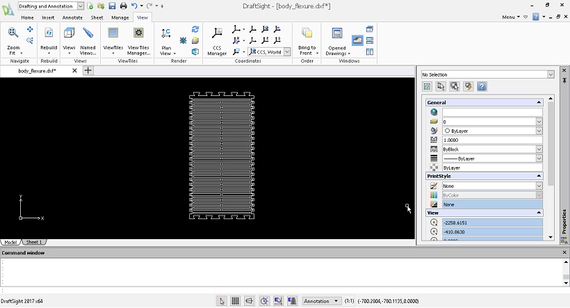
As all bodies are in 3D, it is possible to export a body outline to .dxf in Fusion 360 by first creating a new sketch and projecting the body silhouette to the sketch. I use this procedure to export the body and base to DXF for further editing.

Now the image can be edited within Draftsight.
LESSONS LEARNED
- Learned a bit more about design, stock materials, tooling and wood joints.
- Milled a cnc design for the first time.
FILES
Bedside-table/stool 18mm - DWG file.
Bedside-table/stool ready to mill - DXF file.
Bedside-table/stool - Fusion 360 file
Flexure pattern Template - Fusion 360 file
Flexure pattern 500x955 mm - Fusion 360 file