Designing the board over Eagle
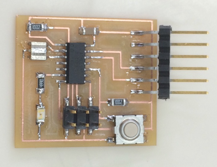
For this weekly assignment I redraw the Echo Hello-World board and added to it a button, a led and two resistors. Here you can see the original board and its design.
First thing to do was to set the Eagle working environment. I've imported the Fablab library, located it on my computer and chose using it within the 'Manage Libraries' window.
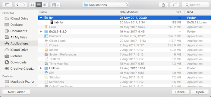
Locating the library
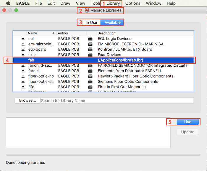
Selecting to use the library out of the available libraries
Orgenizing of the schematic:
- Adding a component
- Net, Name and Label
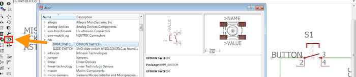
Adding a component
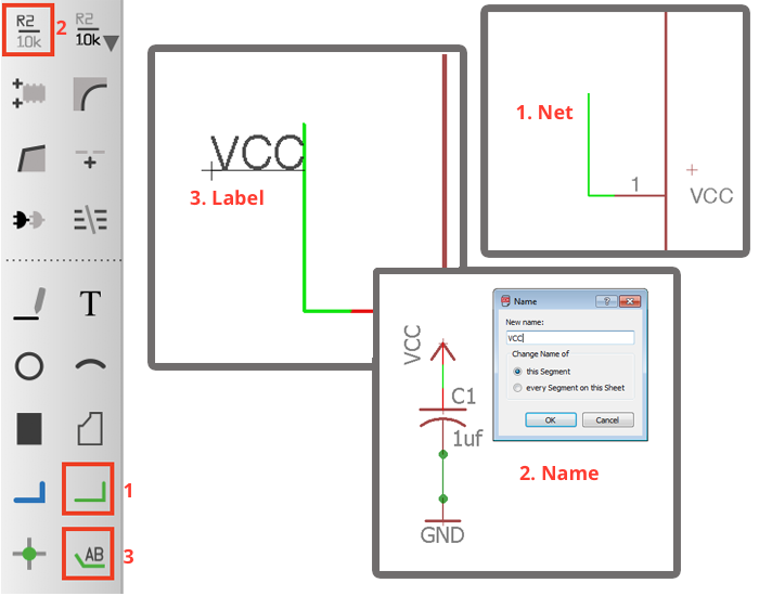
Neting, Naming and Labeling components
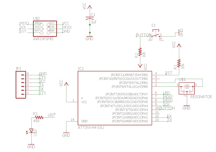
The schematic
Designing tools of the board:
- Locating the components
- Using the different layers
- Tracing between the components
- Setting the design rules for milling
- Exporting PNG’s Interior and Cutout
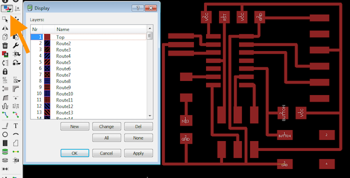
2. Using the different layers
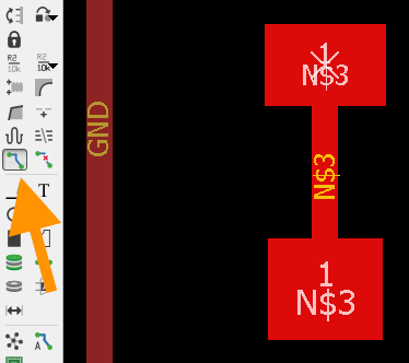
3. Tracing between the components
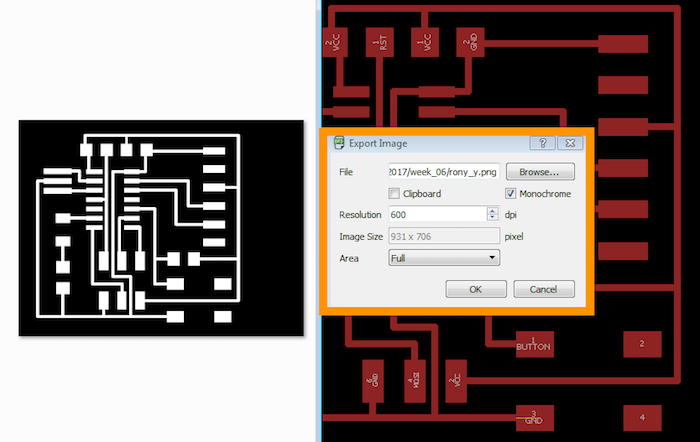
5. Exporting PNG’s Interior and Cutout
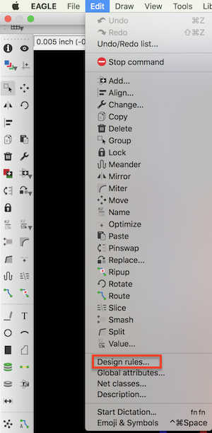
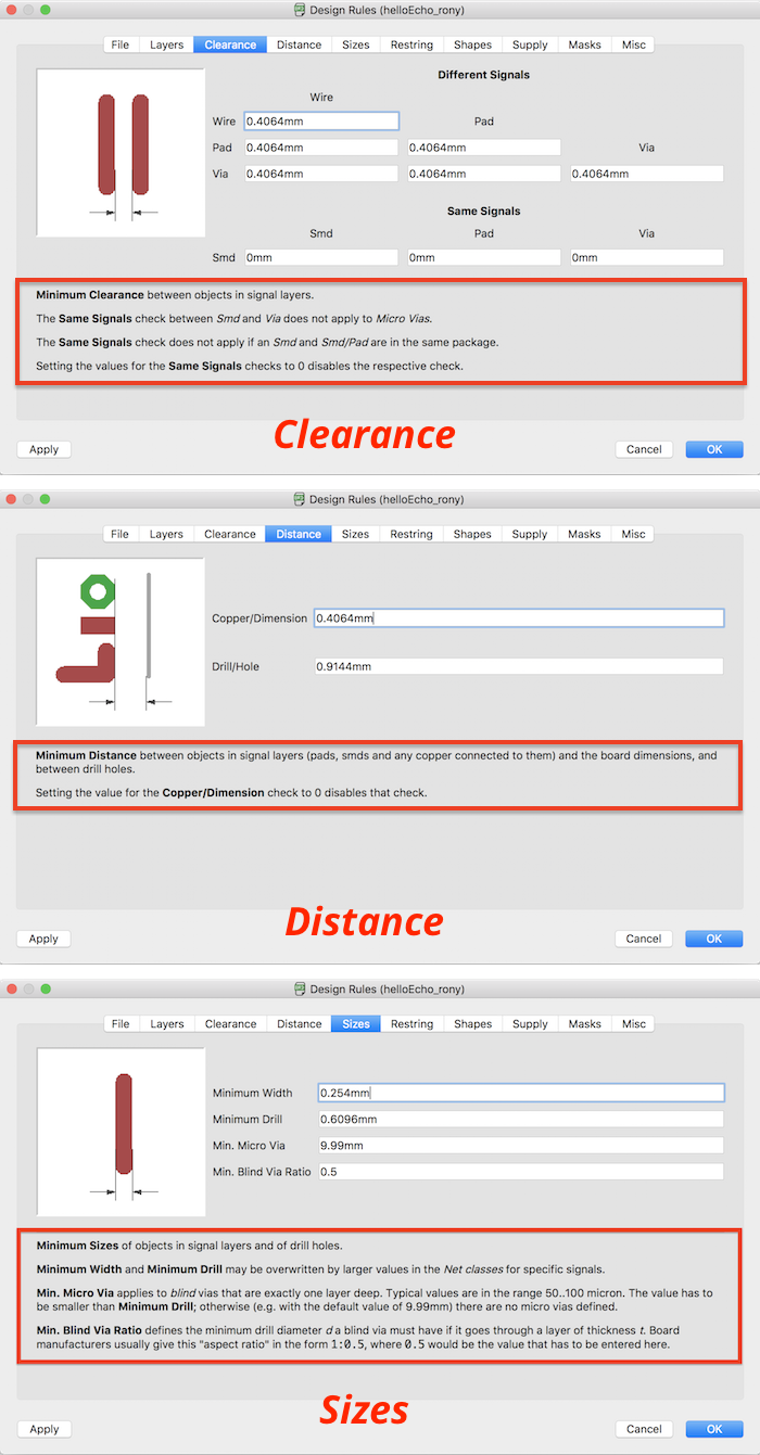
Working with the designing rules
There are several parameters to set over the design rules window:
- To reach the window in the upper ruler choose edit.
- I looked over the variables of three categories:
- Clearance
- Distane
- Sizes
These are the variables influences the result of the milling process. As can seen in the picture, in each category inside the red frame there is the information about the variables setting.
Milling & Stuffing
I’ve imported the PNG files into Fabmoduls and set the parameters first for milling the interior and after for milling the cutout. Here is an explanation about setting the milling parameters.
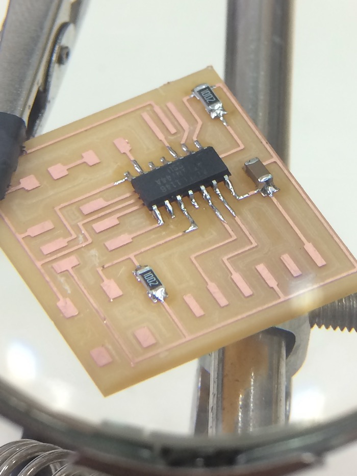
Then cheked the board's traces for any short circuits.
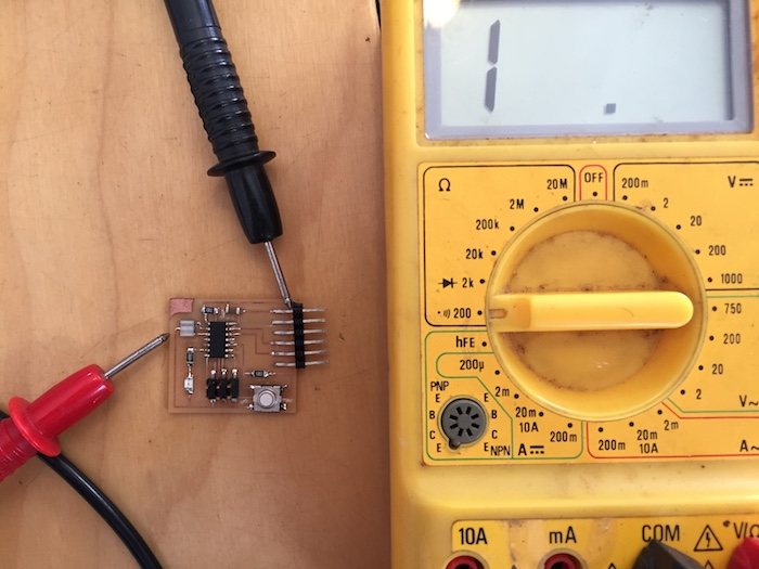
After soldering testing the board again with a multimeter.
The board's BOM:
- 1x ATtiny44
- 2x 10kΩ resistors
- 1x 100kΩ resistor
- 1x FTDI header
- 1x 20MHz resonator
- 1x button-6mm switch
- 1x 1uf capacitor
- 1x LED (Light Emitting Diode)
- 1x 2x3 pin header
The board's files:
download SCH download BRD