Week #15 Networking and Communications
Assignments
Software Used
- EAGLE 7.7.0
- GIMP2.0
- Roland VPanel for MDX-40A
- Fab Modules
- Arduino IDE
Machine Used
- CNC Router Roland MDX-40A
Exercise Repo
You can find all files used in this class in the Fab Academy repository in the button below or a backup in this Google Drive folder.
Past experience
None.
Log
2017 06 13 Learning how to use I2C communication protocol
For this assignment, my plan is to use the two buttons board (Exercise 13) and do a network with my dimmer module (Exercise 10). My intention is to control the dimmer through the buttons. To communicate with the board I will use I2C protocol. To do it, the first step was to learn how to use I2C protocol. For this, I did a tutorial I found on Instructables, called I2C Between Arduinos. The goal of this tutorial was to blink built-in LED once or twice depending on the value received by the slave Arduino, sent by the master one. The video bellow shows it working.
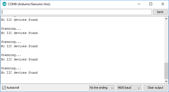
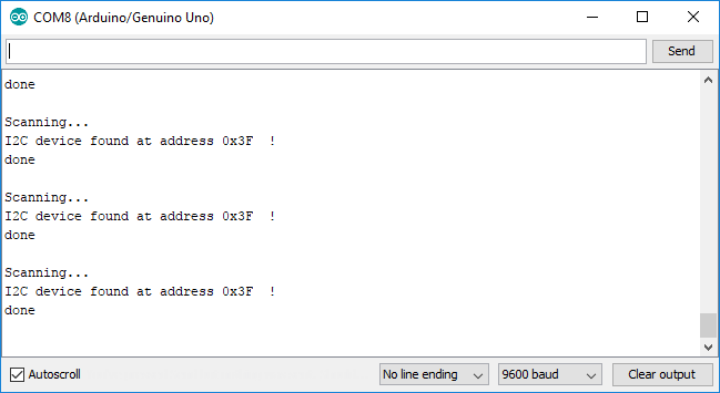
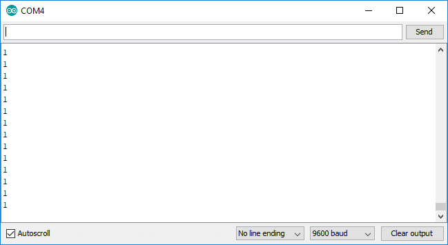
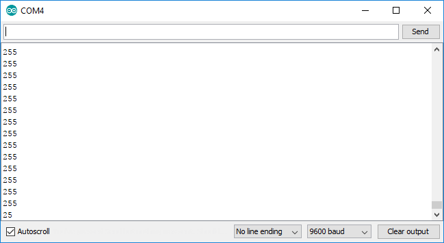
With slave (dimmer) and master (buttons) boards working, I modified the codes I used before to meet my goal (control the lamp intensity with buttons). I have no issue programming the dimmer board (slave), but the button board (master) I had and issue related with the library Wire. I did a quick search and found a topic about it on Arduino Playground, called I2C (master and slave) on the ATtiny85. The solution was to install a specific library for ATtiny44 (TinyWireM), as recommended in that post. Doing this, I was able to upload the program to my boards, but the communication was not working yet. To verify if the I2C protocol was working, I used a I2C Scanner. In the first test, it didn't work. Then I verified the connections, and noted that there were two inverted wires. I fixed it and then the communication worked, but I the slave board was not responding to it. I did some tests printing data on serial to see what information was being sent. I was expecting to send 1 when I pressed button 1 and -1 when I pressed button 2. But when I printed it on serial monitor, I noticed that Arduino interprets -1 as 255. I fix the code replacing '-1' by '255' and then it worked. First, I tested what was happening via serial monitor, then I tested with the lamp. The pictures and videos bellow show this process.
I2C_Master_Buttons Commented code
This code can be found in the zip folder, inside the folder "I2C_Master_Buttons".
// Include the required Wire library for I2C #include#include // set pin numbers: const int button1Pin = 3; // the number of the pushbutton1 pin const int button2Pin = 2; // the number of the pushbutton2 pin const int ledPin = 8; // the number of the LED pin int button1State = 0, button2State = 0; // variables for reading the pushbutton status int z = 0; void setup() { // initialize the LED pin as an output: pinMode(ledPin, OUTPUT); // initialize the pushbutton pin as an input: pinMode(button1Pin, INPUT); pinMode(button2Pin, INPUT); // Start the I2C Bus as Master TinyWireM.begin(); } void loop() { TinyWireM.beginTransmission(9); // transmit to device #9 TinyWireM.send(z); // sends x TinyWireM.endTransmission(); // stop transmitting // read the state of the pushbutton value: button1State = digitalRead(button1Pin); button2State = digitalRead(button2Pin); // check if the pushbutton is pressed. // if it is, the buttonState is HIGH: if (button1State == LOW || button2State ==LOW) { // turn LED on: digitalWrite(ledPin, LOW); } else { // turn LED off: digitalWrite(ledPin, HIGH); } // read the state of the pushbutton value: // storege a valeu z to communicate with slave board // if z = 1 increase intesity // if z = 255 decrease intensity z = button2State - button1State; /*//to test its logic I used something visual * if (z == 0) { // turn LED on: digitalWrite(ledPin, HIGH); } else if (z == 1) { digitalWrite(ledPin, LOW); delay(500); digitalWrite(ledPin, HIGH); delay(500); digitalWrite(ledPin, LOW); delay(500); digitalWrite(ledPin, HIGH); delay(500); digitalWrite(ledPin, LOW); delay(500); digitalWrite(ledPin, HIGH); delay(2000); } else if (z == 255){ digitalWrite(ledPin, LOW); delay(500); digitalWrite(ledPin, HIGH); delay(2000); } else{ digitalWrite(ledPin, LOW); }*/ } //delay(500);
I2C_Slave_Dimmer Commented code
To facilitate the comprehension about networking, the code shown below has just the parts related to I2C communication. If you want to see the entire code, it can be found in the zip folder, inside the folder "I2C_Slave_Dimmer".
#include// Include the required Wire library for I2C void setup() { Wire.begin(9); // Start the I2C Bus as Slave on address 9 Wire.onReceive(receiveEvent); // Attach a function to trigger when something is received. } void receiveEvent(int bytes) { z = Wire.read(); // read one character from the I2C } void loop(){ /*//to test theI2C communication Serial.println(z); delay(1000);*/ }