Week #10 Output Devices
Assigments
Software Used
- EAGLE 7.7.0
- GIMP2.0
- Roland VPanel for MDX-40A
- Fab Modules
Machine Used
- CNC Router Roland MDX-40A
Exercise Repo
You can find all files used in this class in the Fab Academy repository in the button below or a backup in this Google Drive folder.
Past experience
Only the assigments from Week #04 Week #06 and Week #08.
Log
2017 05 18 Redesigning and building a FabKit 0.5
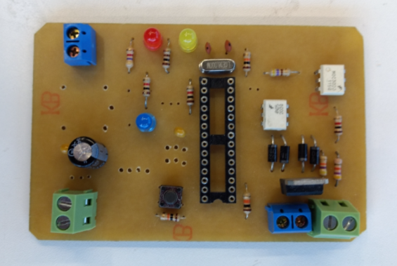
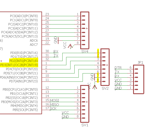
I based my project on FabKit 0.4, made by Massimo Menichinelli. My objective was to remove the LED and the button and add a 6-pin programming header for programming the board. I also removed one of the capacitors, since I didn't found it very useful. Acording the microcontroler datasheet, the board just need two capacitors to work as filters, a big and a small one. The images below show the project used as reference and my modifications.
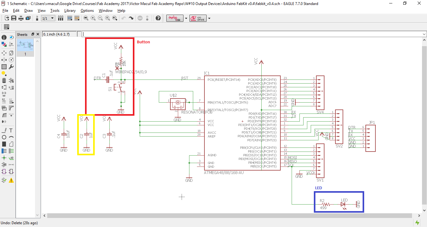
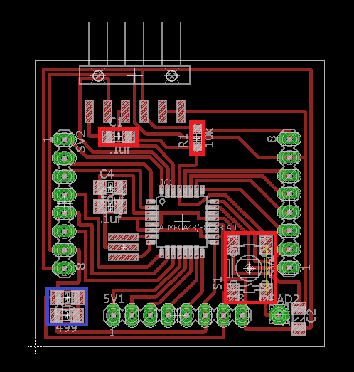
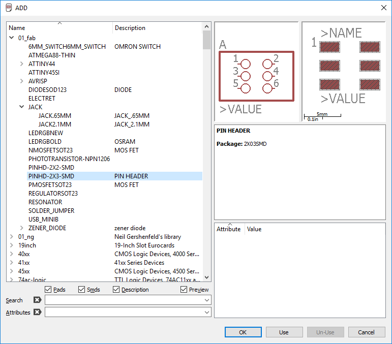
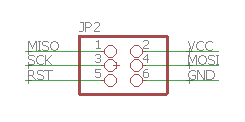
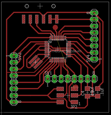
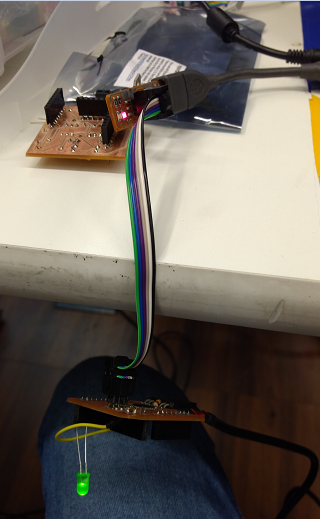
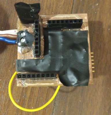
As I was having difficult in connecting all components, I decided to use a jumpper to connect the reset pin. To make it easy, I left an area for the holes, connect to the pins. It is represented in the picture bellow by the yellow line. To produce the PCB, I used Fab Modules, as usual. The holes for the 8-pin connectors were done using a drill bench.
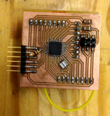
After solder all components I double check my board design with Kenzo before connect it to the electricity and he recommended me to put a 10k ohms resistor between reset pin and the connector. The final result is shown in the picture bellow.
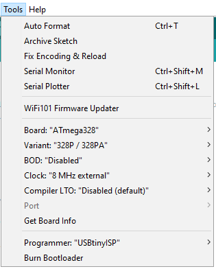
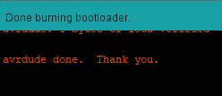
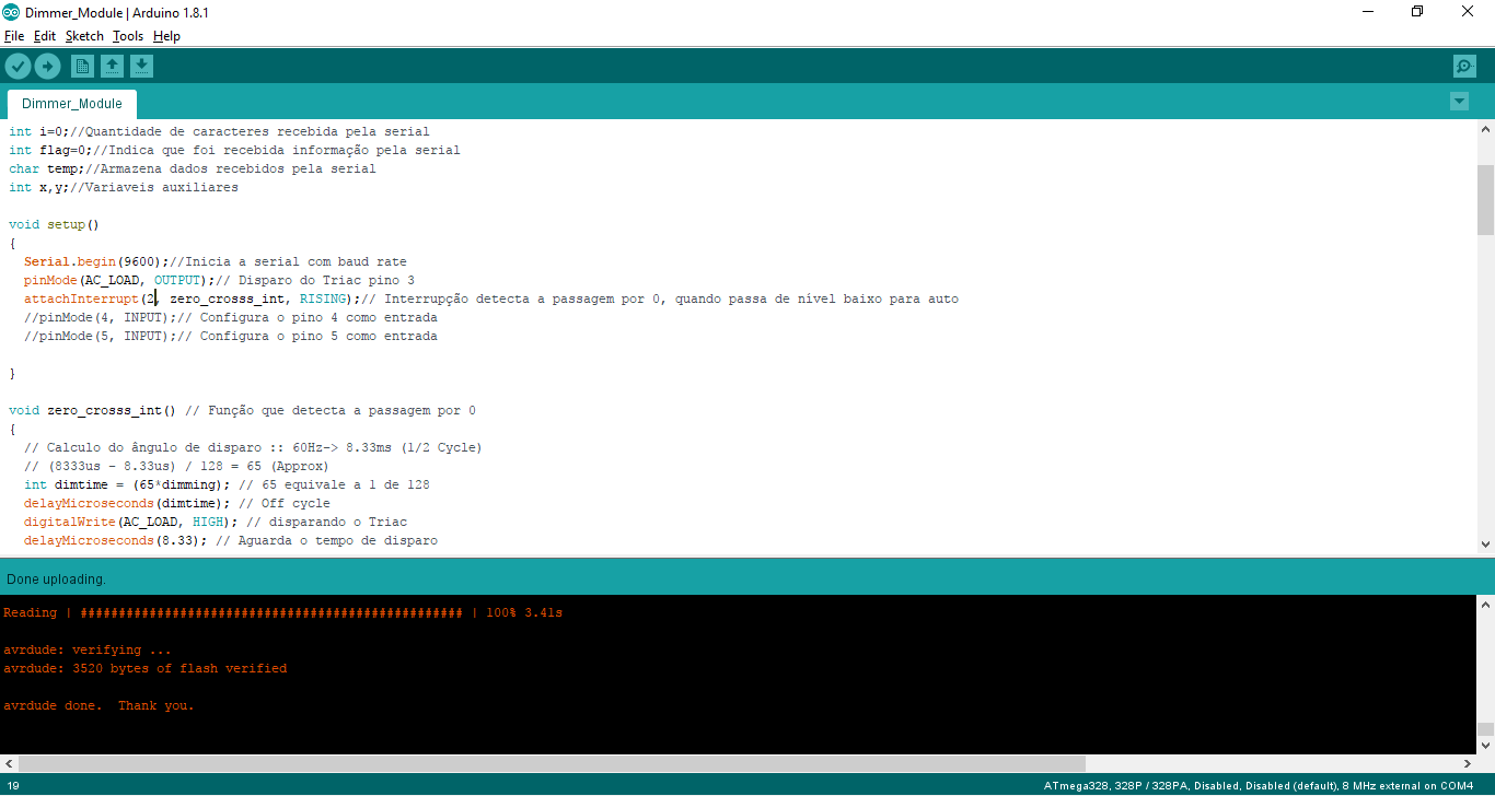
With the PCB done, was time to program it. First thing was to burn bootloader. I had no problem doing it. The seetings I used are listed in the picture bellow. But after that I was having an issue to program my FabKit 0.5. The error message as well as the message shown after burn bootloader can be find on Google Drive folder for this assigment. To solve this issue, I did Upload while pressing Shift, as suggested on MiniCore documentation, and it worked! (=
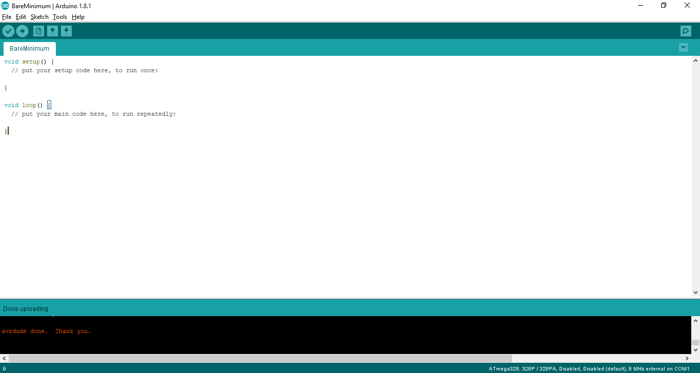
To make sure that it was working, I uploaded Blink exemple as a test. And it worked again! (= Great momentafter some frustrations.
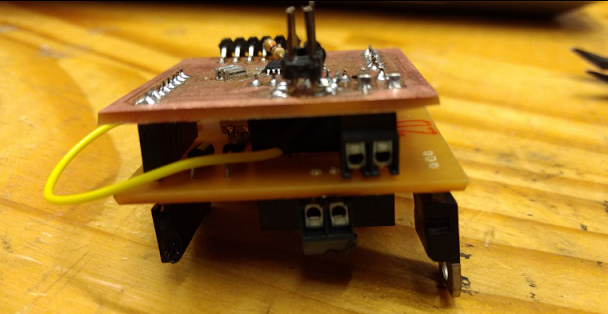
This board will be used to control the intensity of a lamp, as part of my final product. To do it I will use a dimmer module, as followed. .
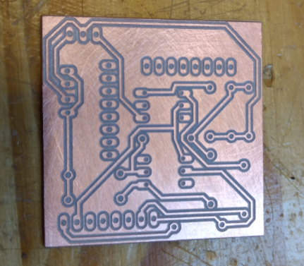
2017 05 26 Designing the dimmer shield
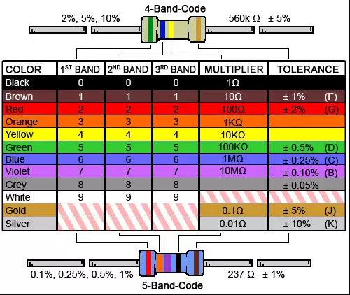
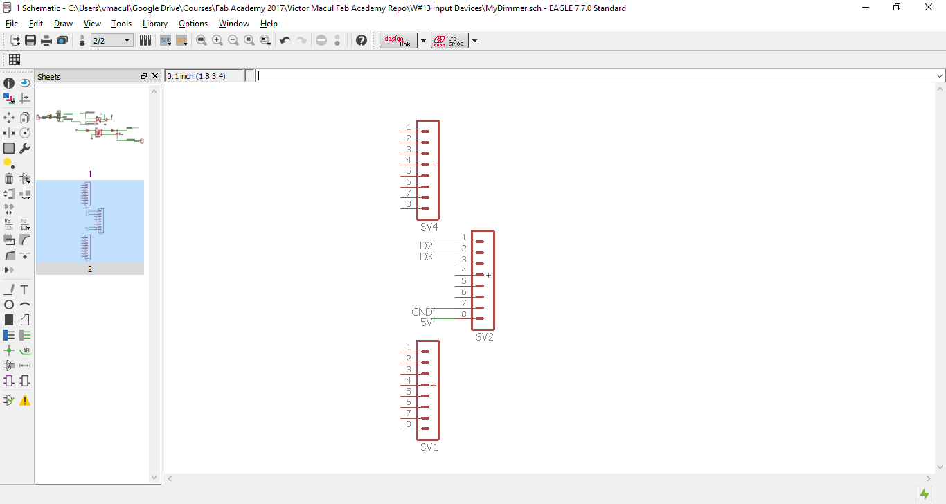
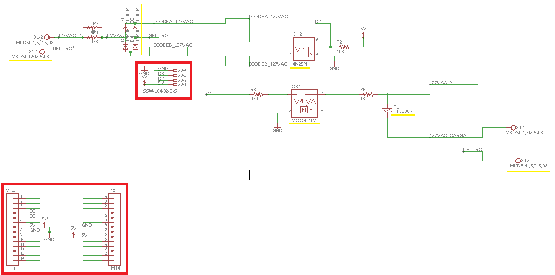
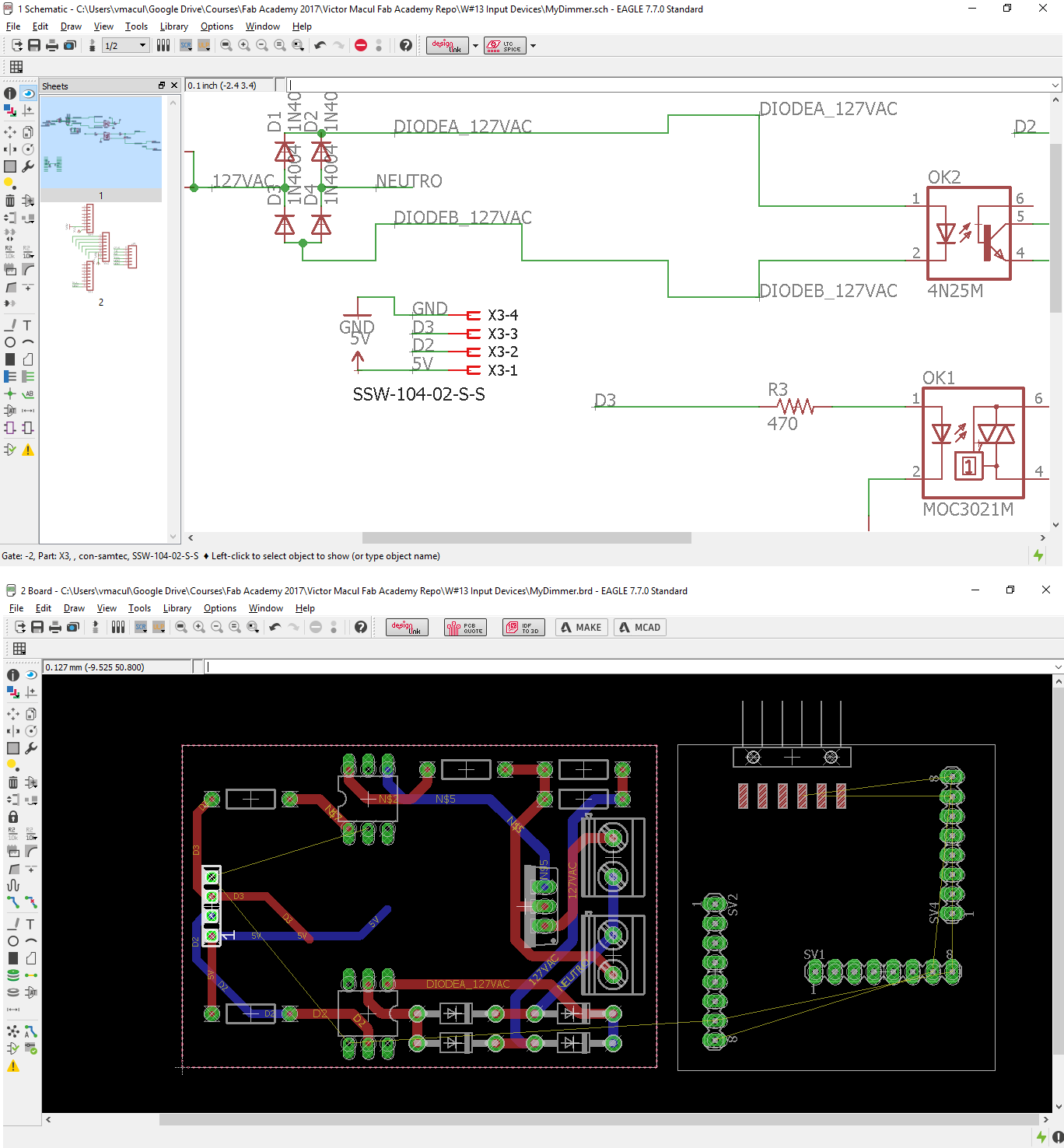
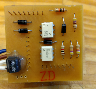
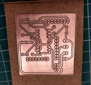
Talking about my project with some colleagues from Insper Fab Lab, I discovered that there was a dimmer module there working and another one that was not working. I started to design my own module to fit in my microcontroller board, using a project as reference as well as the FabKit 0.5 board. In this stage, i used the microcontroller datasheet to identify which pins were the D2 and D3. As I said, I found a broken dimmer at my lab, and I disassembled it to use its components. For this reason, I changed some components on the dimmer schematic to adapt it to the components I have available. Picking the components was a nice task, because I learned how to read the resistor color code. While redesigning the board I learned another thing. I discovered a nice feature in Eagle, called "show" (represented by an eye icon) that is very useful to find an specific component while altering between schematic and board views. The pictures bellow show this process of redesign the dimmer module.
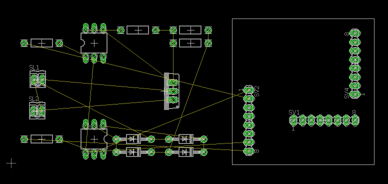
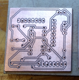
2017 06 01 Making my dimmer module shield for FabKit 0.5
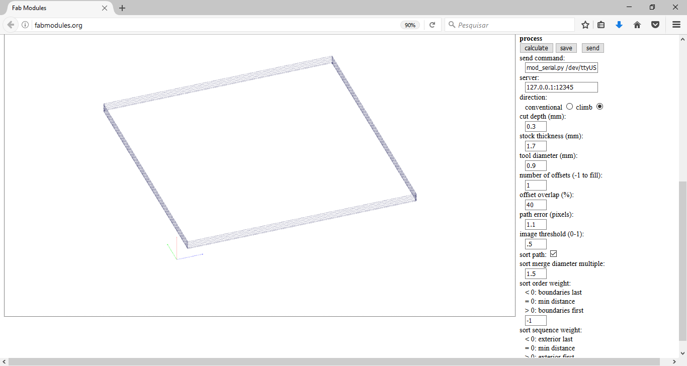
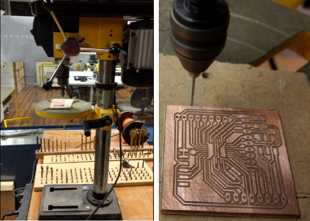
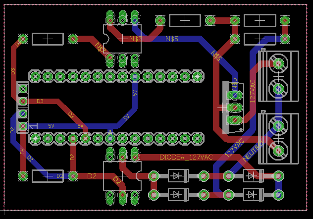
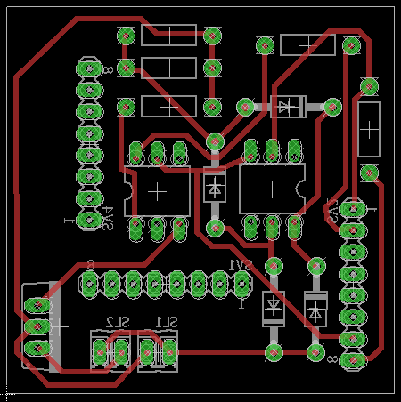
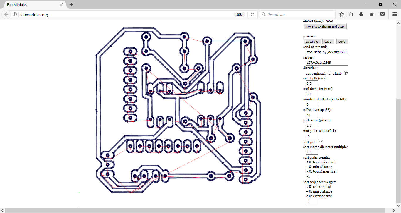
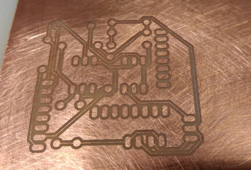
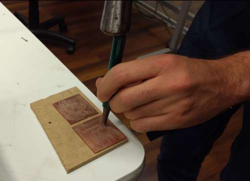
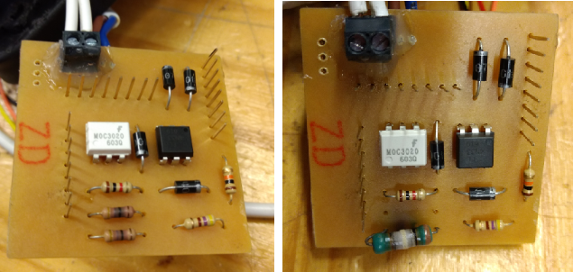
With the board design finished, was time to make the PCB. To do it I used Fab Module, as usual. The parameters used are showed in the pictures bellow, as well as its process. I had to do this process twice, because at the first time I damage the PCB while soldering. For the next time, I improved the process of making the holes. In the first time, I used the drill bench (the same I used to make the FabKit 0.5). But, this time, I didn't have done the pre holes, and I had to use a punch to mark then. The result was not so good. For this reason, after kill the first board, I prepared the images on GIMP before send it to Fab Modules to do the pre holes in the Roland mill. And to make the holes, I decided to use a Dremel, because our drill bench was vibrating a lot, and the drill bit was not well centered. At the second try, the result was much better, and I could make my own dimmer module shield for my FabKit 0.5. Simple task, but a lot of learning for me.
2017 06 01 Programing FabKit 0.5 with dimmer code
For programming my dimmer module I used as reference a tutorial from Laboratório de Garagem. The video bellow explain the code in details.
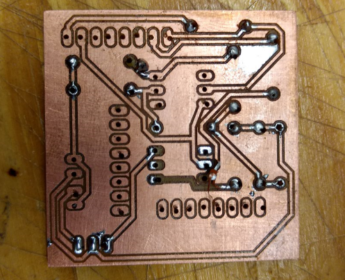
2017 06 06 Fixing Dimmer Module
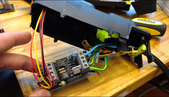
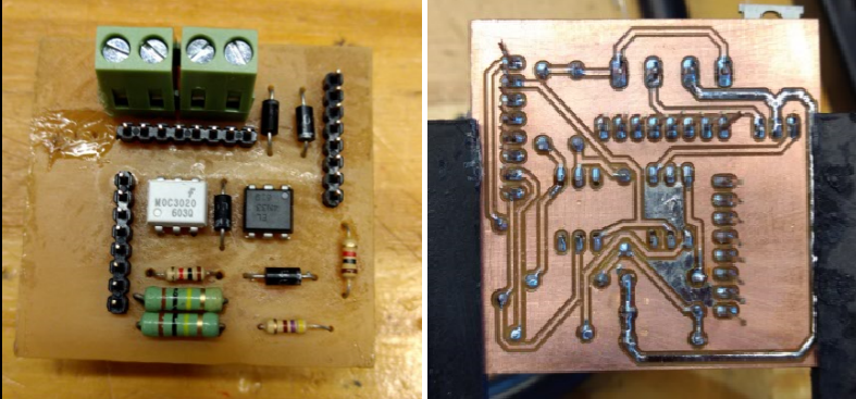
I spent a lot of time fixing some issues in my dimmer module checking the connections. I broke the triac component and the bornes loose the connections while mounting the AC cables. So I had to redo this connections, and I reinforced it with hot glue. To avoid electric shock I also isolated the PCB with an insulating tape.
2017 06 07 Programming FabKit 0.5
I started the day thinking that would be just upload the code to FabKit and it would work. Sweet illusion. When I tried to upload the code to FabKit, an error message appear: "avrdude: programmer operation not supported [...] Double check connections and try again, or use -F to override this check." (the complete message can be found on Google Drive folder). I tried all possibilities. Another ISP programmer. Another cable. To connect the cable in all directions. To reset Arduino IDE. To reset my notebook. Another notebook. To wash the PCB with alcohol. Even to change the microcontroller for a new one. And it didn't work. At this moment I ask for the held of a friend. He taught me how to use AVRDUDESS to verify the communication between Arduino IDE and the microcontroller. No response.. I was complaining him that on the day before I could make a blink a LED with this same board, and today, without doing nothing instead saving the PCB in my Fab Academy project box for one night, it was not working more. At that time, as a last try, he suggested me to heat the soldering with a thermal blower, in the case of some trace has broken during storage. I did it, and finally, it worked again and could upload the program.
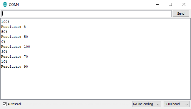
I change some small details in the code, such as, (1) the maximum resolution that I would allow the lamp work to avoid it to blink; and (2) comment the code related to buttons input. After programming the board I was able to communicate with my FabKit via serial monitor. A happy moment! But, when I tried to connect the dimmer shield on FabKit and connect the motor on the grid, one more issue. It didn't work. I verified all the connections with a multimeter, double checked the board design and assembly of components, and didn't figured out what was wrong. 220V was arriving at the input borne, 5V at the microcontroller, but was no energy in the output borne.
2017 06 08 Where are the problem?
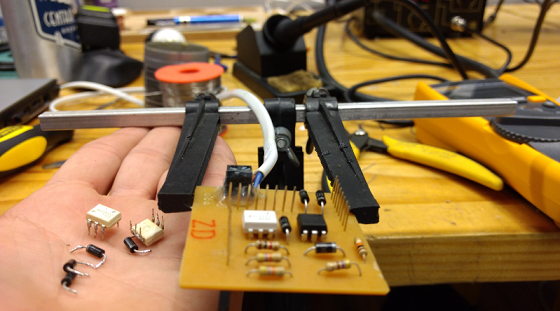
In a way to identify where was the problem I took decided to separate the elements (software, microcontroller, dimmer module, and output) and test one by one. To do it, I took an Arduino Uno, a commercial dimmer module, and a lamp (part of an experiment that a colleague realized during the semester with the students). The first test was combining my code, with these 3 external elements. And, it worked! The second test was to combine my FabKit 0.5 programed with my code and commercial dimmer model and the lamp. And it also worked. With these two tests, I was sure that the problem was at my dimmer module. But where in it? I didn't know. If you remember, I used some components from a board that wasn't working too to build my mine. For this reason, there was a chance that these components were broken. Then, I decided to change some of them: 4 diodes and 2 IC. I did it, and the dimmer was still not working. But in this last test I noticed that my board was heating up, in the two 47k ohms resistors in parallel. Advised by a colleague I changed them by one resistor with higher power, that I found in the lab. The problem was that this resistor had just 1k ohms. I tried, but it started to burn. In the third try, I changed it by two 100k ohms resistor in parallel. And finally, it stopped to heat. But, the dimmer was still not working. For the next test I decided to change the last critical component: the Triac. The problem was that I didn't have more of it in the lab. So I decided to disassemble it from the commercial dimer module and soldering on my PCB. I did it, however, after lots of rework in this PCB the traces were in a bad situation and I was not able to connect the triac with other components. Frustrated, I want to bed, thinking in rebuild the board on the next day. The videos and pictures bellow show these tests.
2017 06 09 A step over: rebuilding the board
Before build another board, I decided to test the circuit and the components in a breadboard. First, I used an Arduino Uno to focus the test on my circuit and it worked! Comparing my dimmer with the commercial one, I noticed that instead of use a 10k ohms resistor, it was using a 1k ohm. I did a test to see the difference and I noticed that the brightness was more intense with the 1k. The video and pictures bellow show these tests. Just to have a better knowledge about where was the problem, I tested the old ICs. The 4N25 was actually broken. Then I tested with my FabKit 0.5 and it didn't work. I was not even able to communicate with the microcontroller via serial. Then, I realized that it could be cold solder again. I used the thermal blower to heat the soldering and then wash the PCB with alcohol. After this I tested and it worked! For the new board I did some improvements, making thicker traces for high voltage.
When I was soldering the components on my new board, I did a mistake and put the Triac in the wrong orientation. It took me a long time to identify why my board was not working, but when a discovered this mistake, I realized that I allowed 220V to get on 4N25, and that probably this component would be broken. I changed this component, fixed the Triac orientation and tested the board again using an Arduino, and it worked. Then, I tested using my FabKit and it worked too! Assignment completed! The videos bellow show these two final tests.
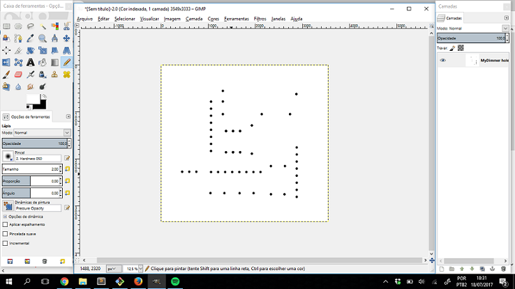
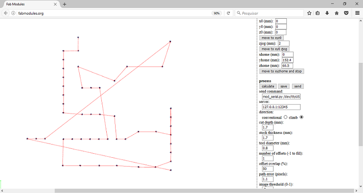
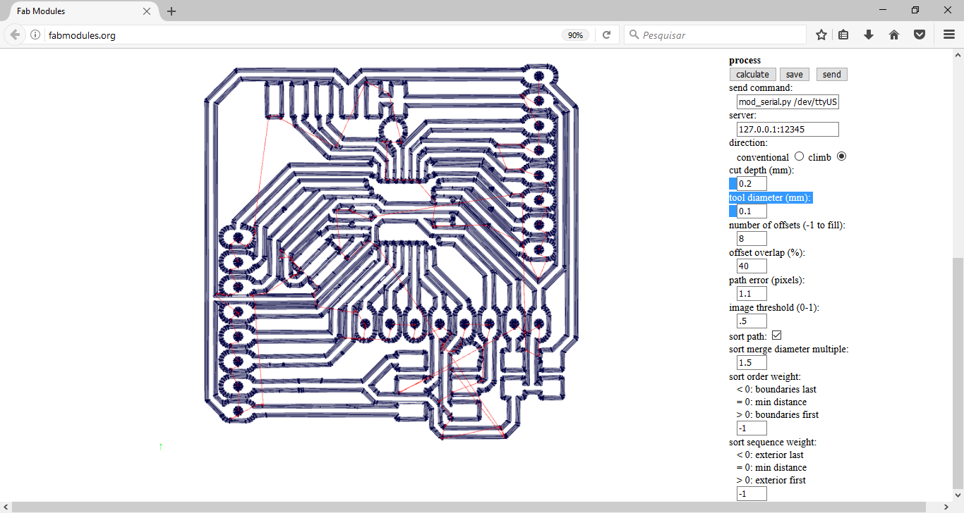
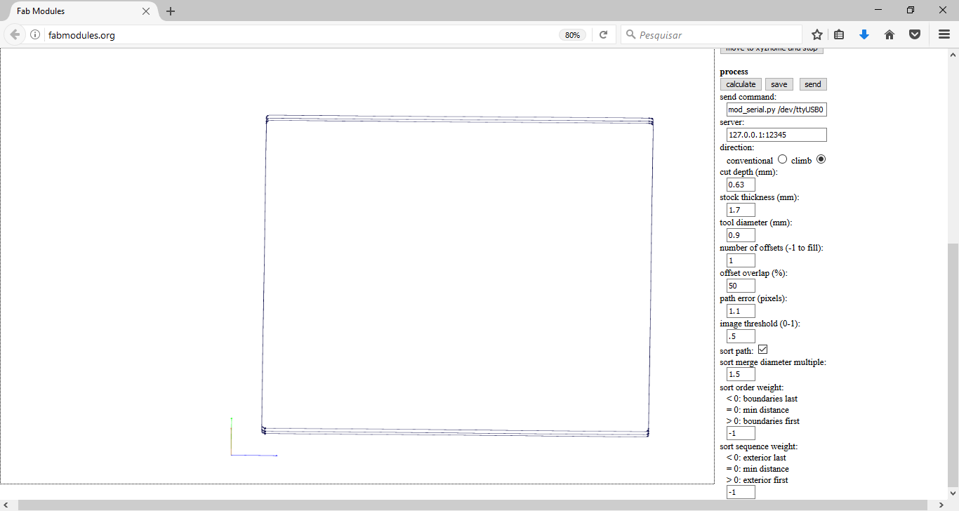
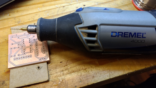
2017 07 18 Improvements: making the holes on Fab Modules
To facilitate the fabrication of the PCB, I prepared the files to make the holes in the Roland mill, using a 1,2mm drill bit. I used GIMP to prepare the image to be processed in Fab modules. To make the holes using the same drill bit, I did all holes the same size. If not, Fab Modules would mill the larger holes and this could break the drill bits. The pictures bellow show how it woulbe be through the simulation made in Fab Modules. The files are already updated according to this milling strategy, and can be found in the zip folder under the name "MyDimmer holes.rml".