Week #3 Computer-Controlled Cutting
Assignments
Software Used
- Fusion 360
- LaserCAD v7.53
- Inkscape
- Roland CutStudio
Machine Used
- Laser Cutter ecnc (Made in Brasil)
- Epilog Laser Mini
- Roland Vinyl Cutter
Exercise Repo
You can find all files used in this class in the Fab Academy repository in the button below or a backup in this Google Drive folder.
Past experience
Log
2017 02 10 Making lasercutter test parts in group
This week we had to come to other maker space nearby, called Rhyzos, because our laser cutter is broken. Rhyzos is a makerspace that develop educational methods to K12 and train teachers to work with maker education. For this year they are planning to start a K12 school from scratch.
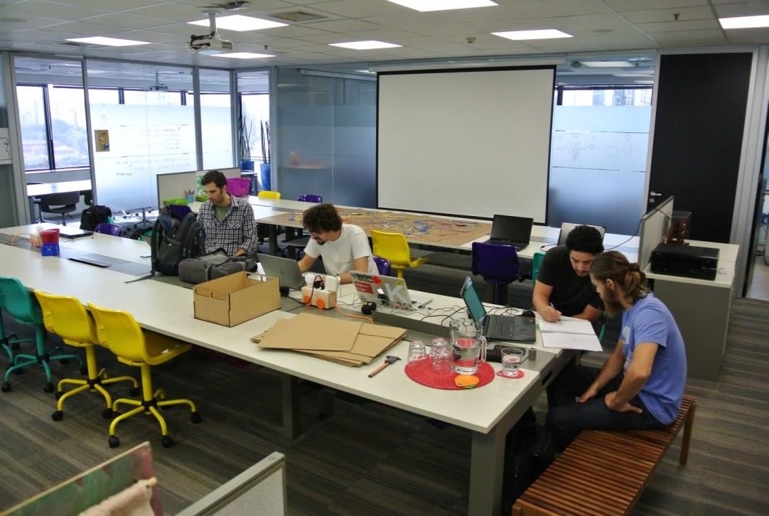
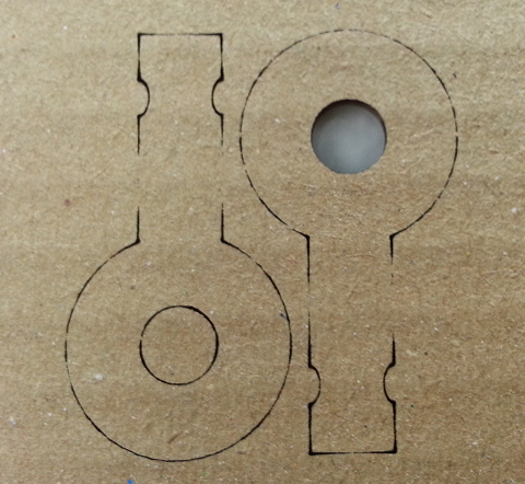
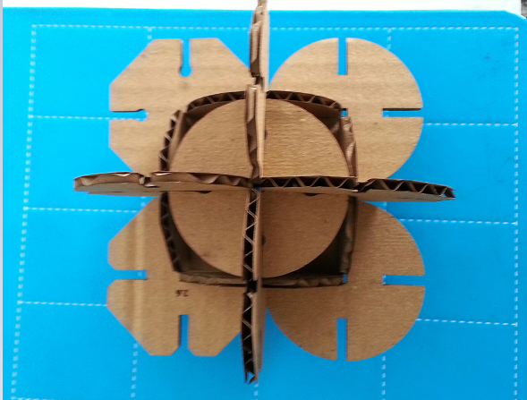
We started by doing the some drawings to test laser settings and the best mesures for a good press-fit joint with cardboard. We did two types tests, as shown on the images below. We noticed thar the orientation of the cardboard has a huge influence on the part structure.
Before start cutting, Vitor Marchi, the Ryzos lab manager, explained us about the leaser bean, how to use the control panel of the machine and how to adjust the correct nozzle height.
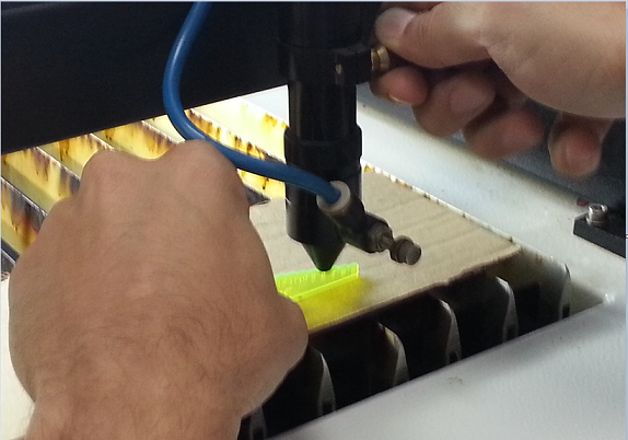
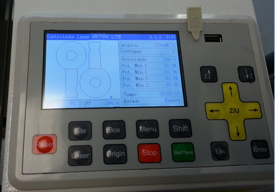
Before use our models, we did a test to identify the best machine settings (speed, power), i.e. the minimum power requested to cut that cardboard thickness. We found taht the combination (50, 50) was the good enouth for our material.
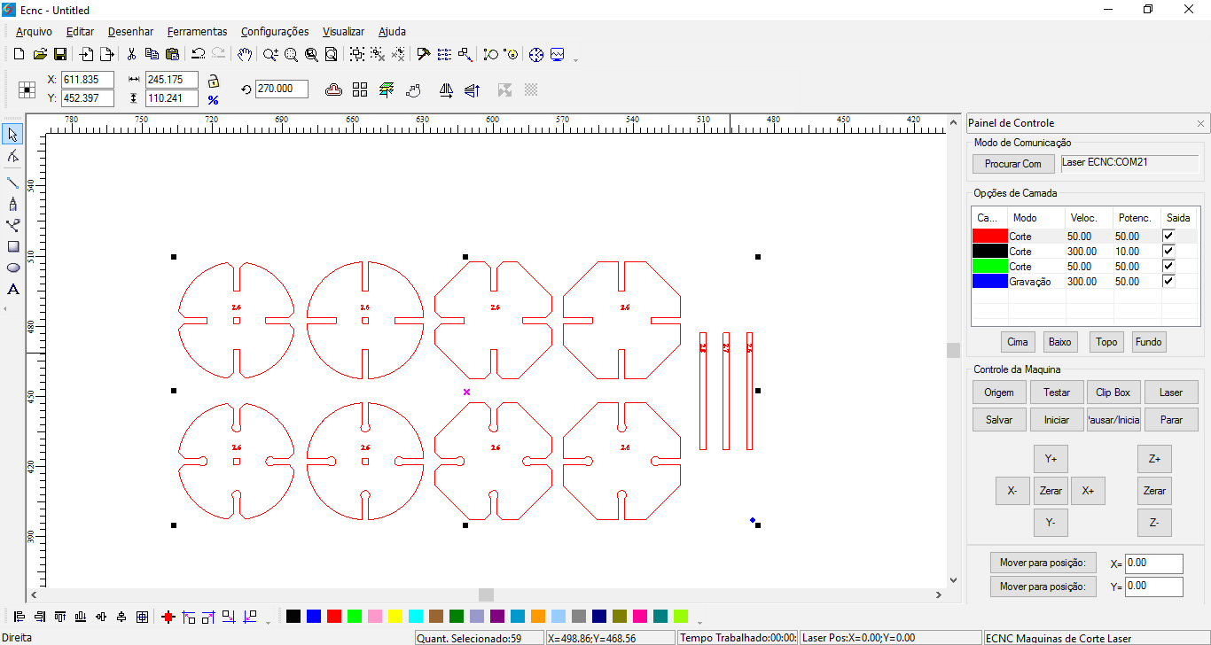
Then, we just had to export the files with dxf extention to open on LaserCAD. We had problems oppening dfx file generated by PTC Creo, and no troubles with the dxf files generated by Fusion 360. To solve this issue we open the dxf file on Inkscape, and save it again with the same extention.
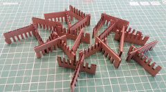
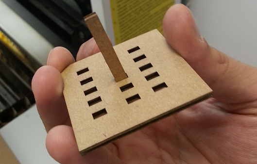
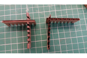
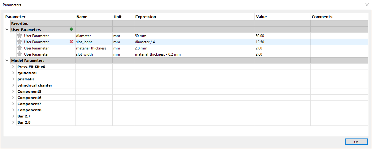
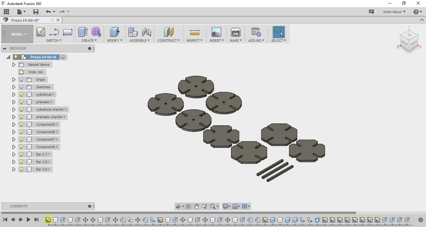
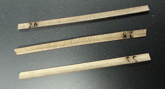
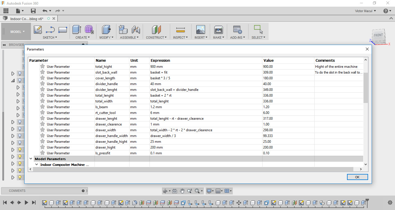
After being familiar with the machine and knowing the right dimensions to get a good press-fit joint, I design my own press-fit kit (in a parametric way, on Fusion 360), and repeated the process to fabricate it. During the fabrication I noticed that I had to change the sequence of layers to raster and cut holes, and than cut the profile. I designed eight types of joints, by varying the profile, the chamfer and the end stop. I also designed three bars, varying the thickness dimension, but it was so thin to be cutted in the laser. To make the sketch to generate the dxf file to be exported I used the "Include 3D Geometry" Fusion feature. And then, I had to delete repeted lines and make them continuous, on LaserCAD. The pictures below ilustrate the press-fit kit design and build process.
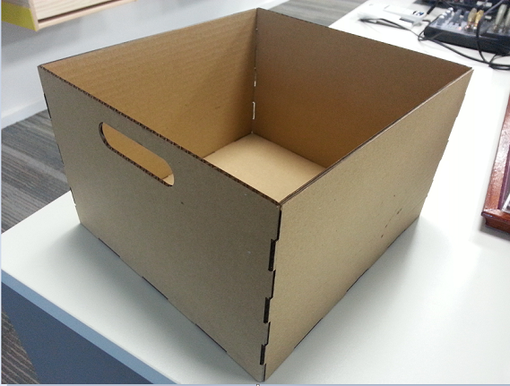
2017 02 11 Making a cardboard prototype of the composter drawer
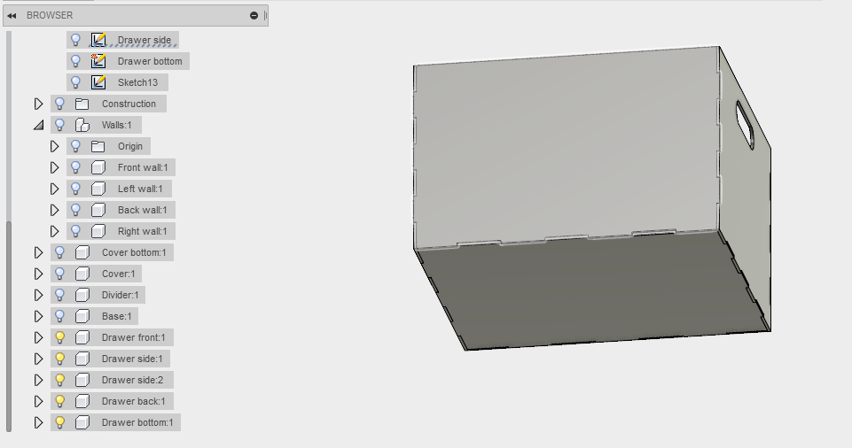
After doing learning the process and completing the assignment, I tried to prototype part of my final project: the composter drawer! I just repeted the process discribed above: parametric design on Fusion 360, file preparation on LaserCAD, and cardboard laser cutter on Ecnc. I didn't get a good press-fit joint, with this design and material. My impretion is that cardboard is too thin for this design, and the parts interference are not well dimensioned for this material. However it was a nice first try.
2017 02 16 Vinyl Cutter
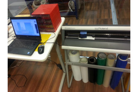
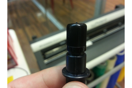
First of all, we begin by preparing the machine, introducing the roller (or piece), aligning the material and adjusting the height of the blade. Kenzo, our instructor, explained where the sensors are positioned and how they work. He also showed us some types of blades and told us before we cut that we should check if there is any residue of glue or dirt on the blade.
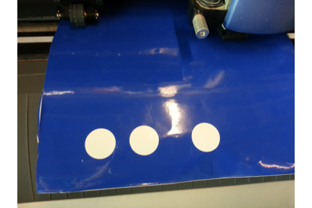
The next step was to test the cutting force, and adjust so that the sticker loosens easily without cutting the paper on which it is affixed. After the tests, we defined the origin of the machine, we imported the parameters of the stock material (File> Cutting Setup> Properties> Getting from machine) to the software (Roland CutStudio), import the file that we desegregate to cut, extract the outline > Image Outline), and start the cut. In a few seconds, the sticker was cut off.
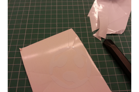
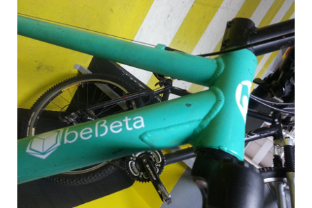
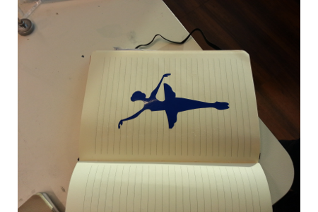
To finish, we removed the sticker from the machine, and with the help of the stylus we removed the negative from the vinyl. With the transfer, we detached the sticker from the paper, and it was ready to be glued somewhere. I decided to cut my company logo, and also the Fab Lab logo. The next day, I taught a colleague to use the machine, and she cut a ballerina.
![]()
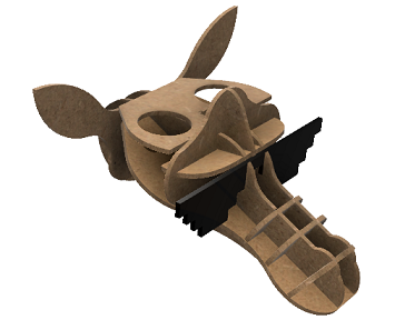
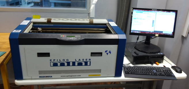
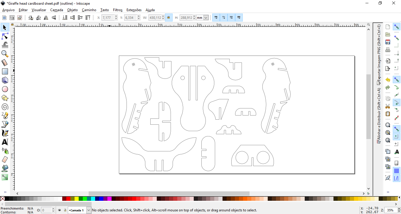
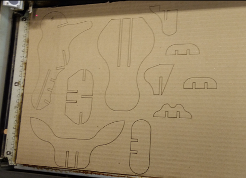
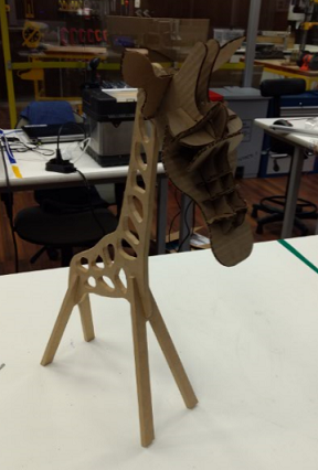
2017 06 18 Making the Giraffe Head
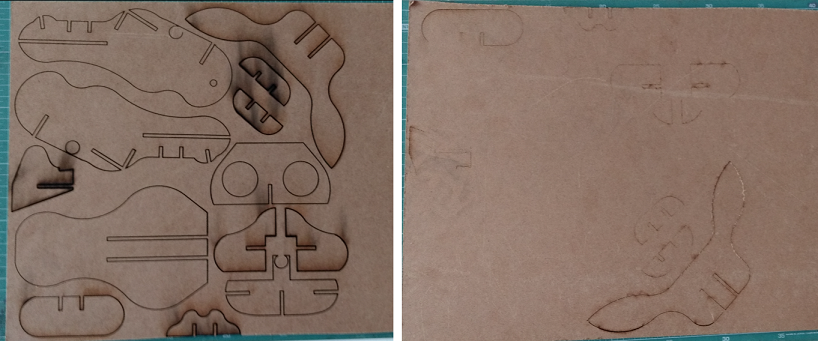
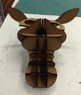
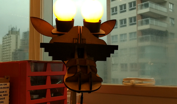
The design process of the Giraffe Head is described in the Exercise 02. It was a iterative process, in witch I did first a cardboard prototype, reesign it and then did it in MDF more two times until get in the final design. To fabricate it I used the laser cutter from Insper Fab Lab, since it was fixed. I followed the tutorial made by our Gurus (available on my Google Drive folder). The first step is to export the dxf file from Fusion to Inskcape. On Inkscape, I distributed the objects on the sheet (300x600mm), eliminated the double lines one by one, changed the vector thickness to 0.025mm, and saved it as PDF to be used in our laser cutter. In the machine, to cut the cardboard , I used the following parameters: Frequency: 2500Hz, Speed 50% and Power 50%. For the first try with MDF I used Frequency 2500Hz, Speed 50% and Power 100%, but it didn't performed well. For the next time I used Frequency 2500Hz, Speed 10% and Power 100%, and even using low speed, I had to cut twice. The pictures bellow show this process.
2017 06 22 Doing a sticker for my final project
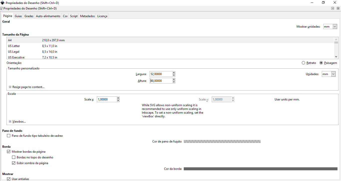
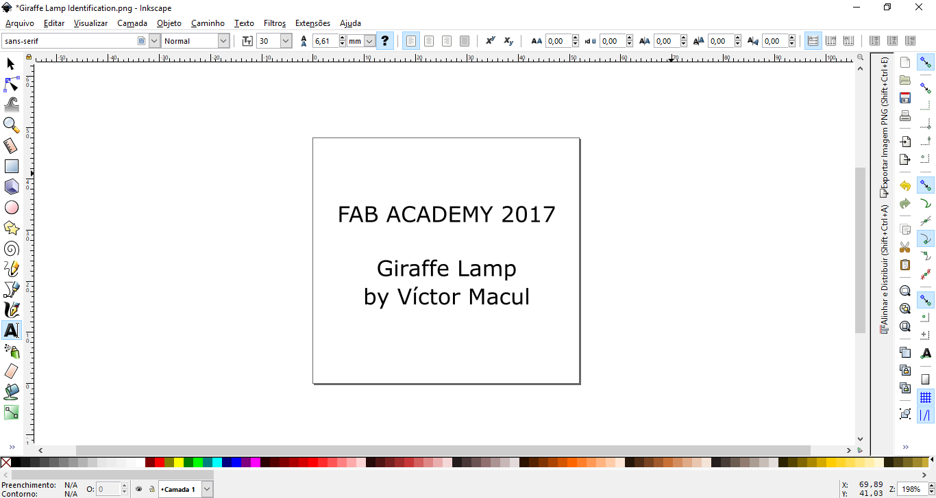
After finish my final project, I drew a sticker to identify it. To do it I use Inkscape, more precisily the Text feature. As I would stick it on the above the PBC holber box, I set the width of my canvas to 52x48mm (box dimension) and ajust the size of the text to fit in this area. I exported it as png and to fabricate I used the same settings described above. The pictures bellow ilustrate it.