ASSIGNMENTS
Week 5 - 3D Scanning and Printing
The assignments for this week were:
- Test the design rules for your printer(s).
- Design and 3D print an object (small, few cm) that could not be made subtractive.
- 3D scan an object (and optionally print it) (extra credit: make your own scanner).
Test The Design Rules
I printed a
model available on thingverse.com, to learn the design rules of 3d
printing. The reason for this test is to fully understand the rules of
3d printing and how the machine functions.
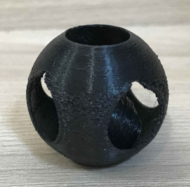
The model that
I chose wasn’t printed exactly how it was in the file, as you can see,
the circle is not perfectly round. One of the reasons it could have
turned out this way is because the file image was to be printed large
scale but I needed to resize the image on a smaller scale so the 3D
printer could print faster. Other reasons could be that I chose a layer
height(mm) and layer thickness (mm) to thin and the low-quality setting
I chose on the Cura software which caused the printer to not properly
print the image. The last reason could be because I didn’t chose the
setting in the Cura softwear called support structure. This setting
allows the machine to build a support structure for an image/object
that is too thin to print on its own and then be removed from the
structure once printed. The structure in my opinion was too thin to
support itself.
Design and 3D Print an Object
For the 3D printed object, I wanted to make a
conical essential oil Extractor which I will use in my final
project.The first step was to make the 3D model in SolidWorks, I also
parametrized all the measurements of the conical essential oil
Extractor. I parametrized the y axis: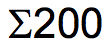 . .
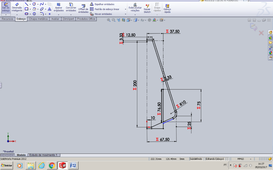
(3D model in an isometric view)
Parametrization:
is using equations and global variables to apply dimensions to your
sketches. The reason for this is to make it easier for the solid works
user to apply larger or smaller dimensions to any of the dimension
measurements using the shortcut of a preset parametrization equation.
For example, all you have to do is change one of the dimension
measurements and it will automatically change them all. The
equation for parametrization in solid works is =Function.
I didn’t know how to parametrized a 3D in
SolidWorks, so I watched some Youtube videos before I started, here is
the one that I could understand the best on how to do it:https://youtu.be/ltRL0qXgo2A
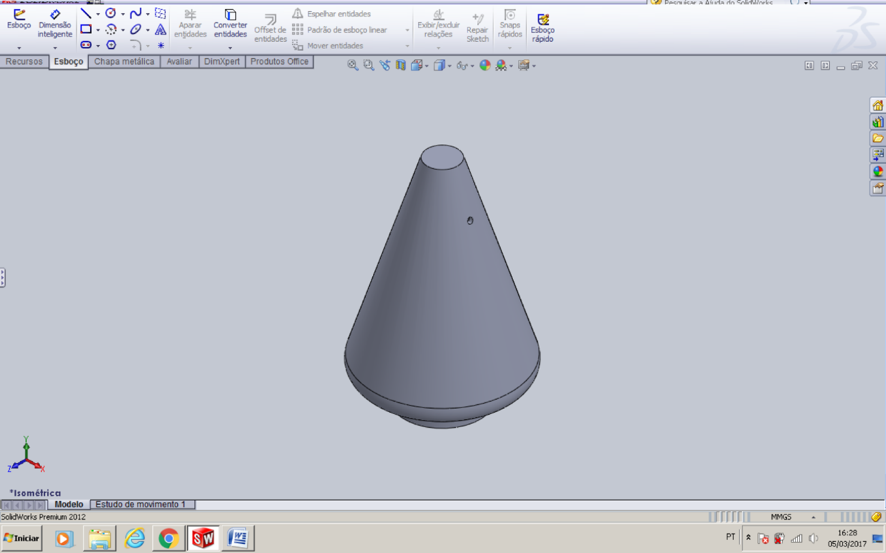
Also below is a picture of my support leg parametrized. It’s not so hard to do it.
Here are the steps of how to design the image using a parametric measure including my measurements:
1) Insert your sketch
2) Click one of the lines of your sketch
and then you click smart dimension tool at the top left of the
window.
3) A small window will appear and Insert the line dimension you prefer in (mm)
4) Create a global variable by clicking the tool next to the red x button
5) Type an = then type in your name for
the variable then accept the variable by clicking on the 
symbol
6) Click on another sketch line and
repeat steps except for this time insert an equation as you can see
in the image bellow and click accept.
7) Continue these steps where you see fit to parametrize the dimensions of your sketch.
If you have any doubts how to use SolidWorks I would like to recommend this video fromYoutube:
https://youtu.be/YlJeaIwrMro?list=PLCE6728E47A919344.
It helped reminde me how to make a 3D model using Solidworks.
Snce I already knew how to use this software since 2015, when I
designed a chemical car to participate in a competition in my
university.
The next step was to convert the 3D model to .stl. So the  (3D
printer) could print my model. The process to do this is, you first
need to click the File tab at the top and then click save as. The save
as window will open up and then you have to click the file format tab
and select the format .stl . Once you chose the format hit save. (3D
printer) could print my model. The process to do this is, you first
need to click the File tab at the top and then click save as. The save
as window will open up and then you have to click the file format tab
and select the format .stl . Once you chose the format hit save.
After that I opened my model in the Cura software, which is the software that the uses.
When I opened up the cura software a basic setting toolbar was on the
left and a theoretical model of my extractor and the inside of the 3D
printer was on the right of the toolbar. A few other things I noticed
were the tool buttons located at the top right, top left and bottom
left.
I played around with the tools and these are the ones I found most useful:
Rotate option- Rotates on 3 axis which is helpful because it allows you to find the best position to print your model.
Scale- Sometimes the program you use to sketch and save the image is
not in mm and can confuse the cura software by converting the image
automatically to mm causing the object to come out very small.
SD- To Save your object on a SD card because the 3D printer only reads SD cards. (Always remember to insert SD card)
Layer Mode- Allows you pull away the layers and see the infill. This also allows you to see where your structure is hallow.
The Settings that I found important are:
Quality:
Layer height (mm)- The larger your layer height is the longer the
print time takes. If you make your layer heights to small you may end
up with gaps in your model. I chose 0.2 mm because it is the
recommended layer height for both printing time and structure support
Shell thickness(mm)- Is the thickness of the outer shell of your model. I chose 1.2 mm.
Fill:
Bottom/top thickness(mm) – This controls the thickness of the bottom
and top layers, the amount of solid layers put down is calculated by
the layer thickness and this value. I chose a thickness of 1mm
Fill Density(%)- Controls how strong the part becomes. Usually set at
20%. For a solid part density is set to 100% and if part is empty it is
set to 0%. I chose 10% for my Extractor because I did not want it to be
fully hallow.
Speed and Temperature:
Print Speed (mm/s)- Affects the quality of your print. The slower the
speed the higher the quality is and the faster the quality gradually
gets worse. I chose a print speed of 30 mm/s.
Support:
Support type- There are 3 different support settings. None creates no
support, touching build plate only creates a support where the support
structure will touch the build platform and the final one is everywhere
which creates support from top to bottom. I chose none.
Platform adhesion type- This allows the filament to flow through the
nozzle before it starts printing your model. Which allows for a
smoother transition into your first layers. The two options are skirt
and brim. I used the brim option because my model didn’t have a lot of
contact with the bed.
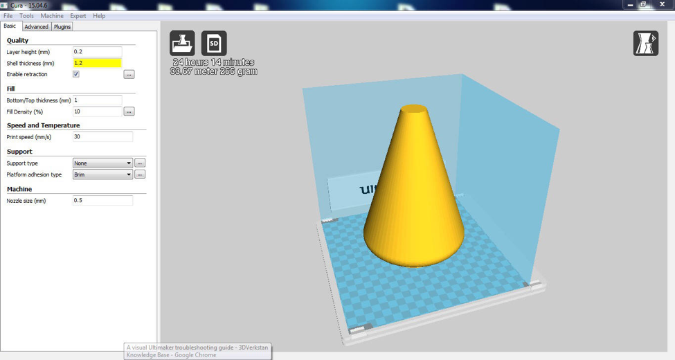
As you can see, it took 24 hours and 14 minutes to print, we left the
machine printing overnight, and was used 33.67 meter and 266 grams of
PLA (polylactic acid).
Here is a helpful link for this process is: https://www.youtube.com/watch?v=6YZD6K7osco
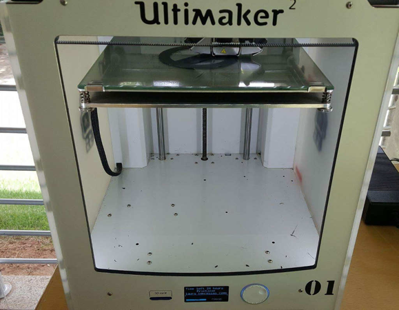
Below is a picture right after the machine started:
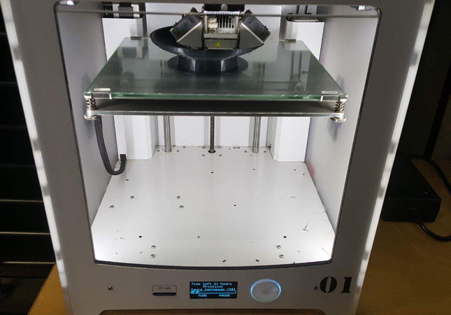
I then took another picture a little later so I could make sure that my
model was printing correctly. It was, so, I left it printing over the
night.
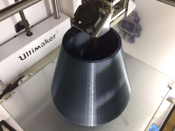
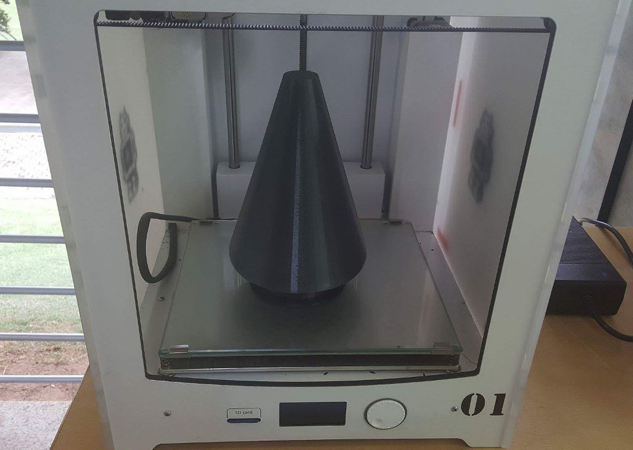
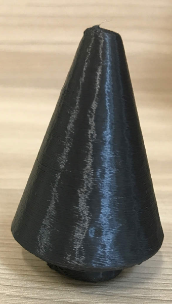
When I arrived at the Fab Lab in the morning, I took another picture.I was very excited to see the extractor was almost done.
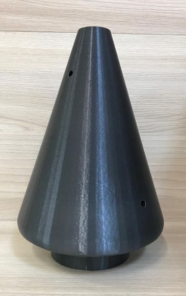
Some hours later, the extractor completed printing.I really liked the
results, the extractor was as perfect as I designed it to be.
3D Scanning
One of the
assignments for this week was to make a scan of what you printed using
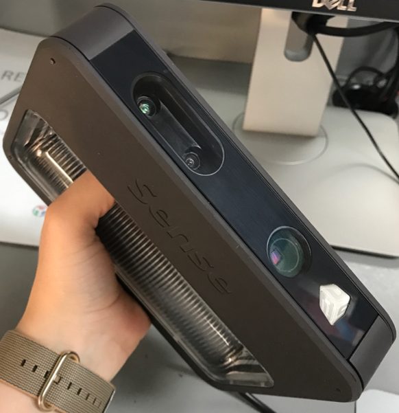
the 3D printer. I used the Sense scanner and software name is Scense 3D
Scanner. to scan my extractor. The machine and software has limitations
on what it can scan. Its limitations include scanning details such as
rolls and internal parts.
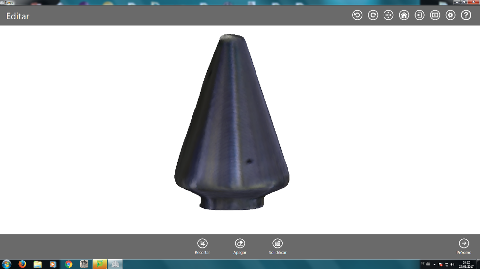
I
didn’t like the result because it was a little
deformed but, I still decided to print it on a small scale because
there wasn’t a use for it other than learning the process. One possible
reason that the scan came out a little deformed was because the environment was very bright which may have interfered with the
scan.
|