- Read technical data sheet (TDS) for the resins that you're using.
- Design and fabricate a 3D mold (~ft2)and produce a fiber composite part in it.
The most
import things we learned in this assignment were; what is a composite
and how to make composite material (composite for short). A composite
is a material made from two or more constituent materials with
significantly different physical or chemical properties that, when
combined, produced a material with characteristics different from the
individual components. Essentially, a composite is a multi-layer
material which is super strong, light weight and waterproof. This
material is commonly used in kayak, repairing and building larger
boats, airplanes, armor for military vehicles and making a verity of
other light weight yet very strong things. This is also used to create
many products where the weight and strength ratio are curial to the
product being efficient.
Read The Material Safety Data Sheet (MSDS) and Technical Data Sheet (TDS) For The Resins That You're Using
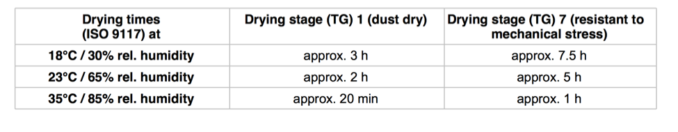
While reading the TDS for RELEST Wind HS topcoat I learned that
technical data sheets are just letting the user know how the chemical
works. For example, the drying times are:
It also includes a very basic safety section. Click link to see an example of a TDS:
http://techinfo.relest.basf-coatings.com/data/relius/techmerk.nsf/getfile.xsp?lang=en&Article=I306-x2xx
After searching for hours, I could not find a MSDS on the resins that I
will be using. I did some research on what a MSDS is. I found out a SDS
is an international form of the MSDS. While MSDS comes in multiple
formats and the SDS is published in one format. Source link:
https://www.safetyservicescompany.com/topic/osha/msds-vs-sds/
Design and Fabricate a 3D Mold (~ft2) and Produce a Fiber Composite Part In It
Cick on the the
Week 7 to go back and see the fallowing steps on how to design and fabricate a 3D and 2D model.
The
first step was to design and fabricate a mold to which our layers
for our compost will form to. At first I used solid works to create a
3D model of a box with dimensions of 14.5 cm x 10 cm x 7 cm. Then, when
I got to the Fab Lab the Fab Lab guru told me that it will
be easier and more efficient to use a 2d model instead, because I would
use the CNC router to cut in 2D. He let me use his computer which had
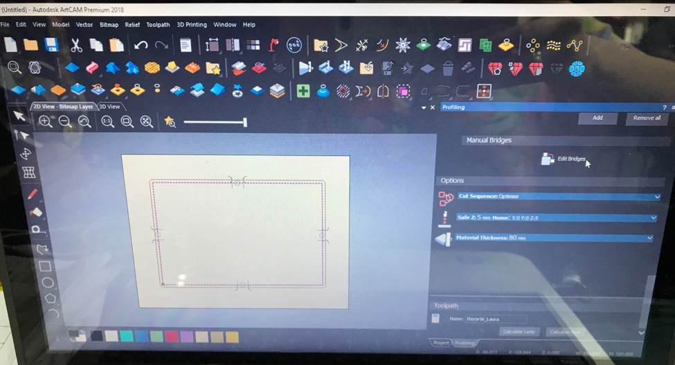
the ArtCAM software on it. I redesigned the box which ended up with the
2D dimentions of 150 mm x 95 mm. Bellow are the pictures of my
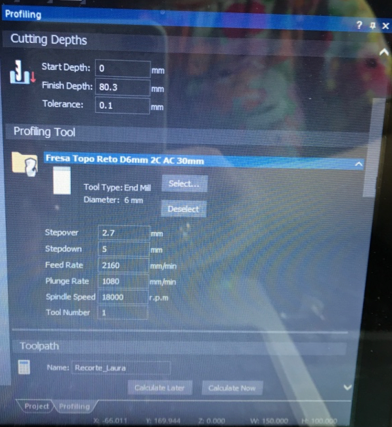
origional Solidworks image. I then created the Toool Paths and
simulated the Tool Paths. Finally I savedmy image to a pindrive.
Below are the images of my created tool paths:
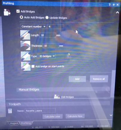
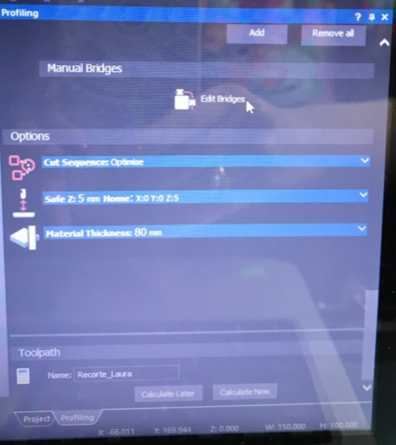
Final image with bridges included below:
Setting Up The Machine and The Material To Cut
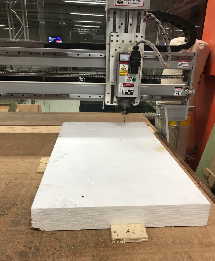
Before you insert your pen drive in the machine, and before you turn
the machine on, place your sheet material with stabilizing supports. In
this case, I used a Styrofoam sheet and drilled in the side stabilizing
wood blocks, as seen in the image below. You need to put these blocks
to stabilize the foam, because when the machine starts your material
can move.
Safety: Most machines that we use at Fab Lab can cause significant bodily harm if the safety measures are not taken into a-count.
Below is a list of safety tips:
• Always remain with the machine
while it is running, and be ready to hit the spacebar to pause the
file, or the stop button to stop
the machine in case of an emergency.
• Always wear eye protection while the machine is running, and have long hair tied back.
• When changing the endmill, Disengage the spindle.
• Use the dust guard.
• Don’t use gloves.
• Caution: Keep collets clean, a
piece of debris or dust between the collet and bit can cause the bit to
spin elliptically, harming bit, part or
even operator.
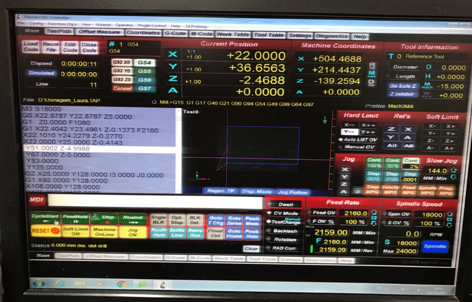
After I placed the material on the table, I opened the file in the
computer that works with the CNC router and then I positioned the X, Y
and Z axis using the “Jog”. Jog settings are located on the right hand
side of the screen under Hard limit settings.After that I needed to air
cut to test my design first. Everythg matched up.
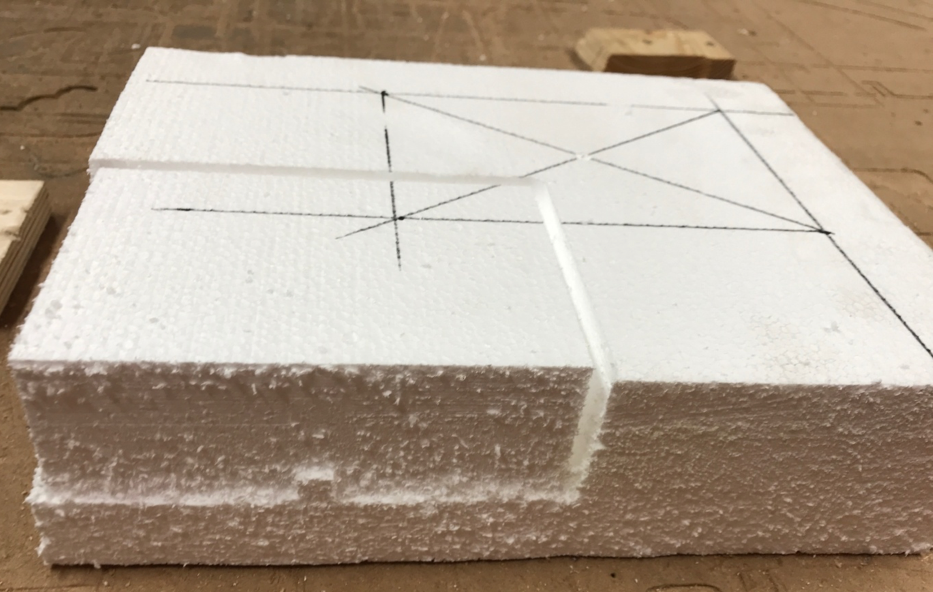
I draw a rectangle on the foam with the measures of my actual
rectangle, but I end up drawing in a wrong position, but it didn’t
affect anything. Since the tool that I used had 8mm, the foam was not
cut all the way through as seen in the picture below.
Video of Router cutting:
https://youtu.be/JTF_Ud9AxuA
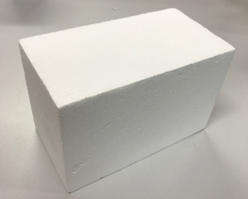
The next steps is to cut the Styrofoam box out of the rest of the
Styrofoam sheet using a saw, then sawing off all uneven parts and
finally sanding the boxes sides smooth. Below are the video links of
these steps:
https://youtu.be/kQK0gsrCPR4
https://youtu.be/_iOhFjQ0cIo
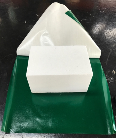
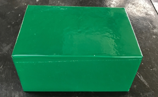
After cutting and sanding the Styrofoam box my rectangle box was ready.
I put the protective green vinyl sticker paper on the rectangle so I
could put the composites layers on the box. This sticker acts as a
protective layer against the epoxy resin mixture that can damage the
Styrofoam mold because, the epoxy resin mixture causes a exothermic
reaction and can melt the foam.
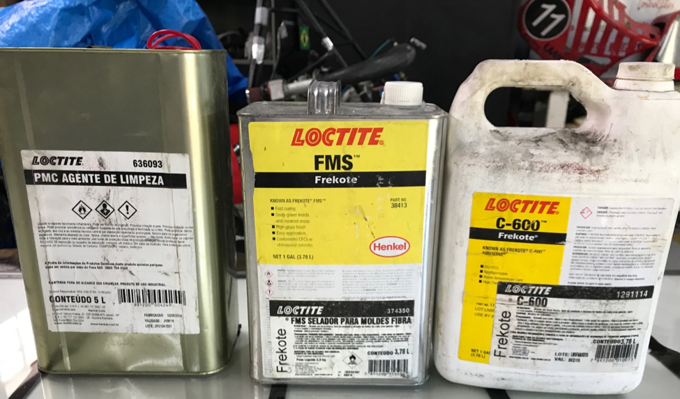
Once I finished the previous steps I needed to clean the surfaces by
brushing one layer of cleaning assistant chemical on all the sides.
Then I brush on the two-mold release (FMS and c-600) chemicals which
not only help to release the mold from the composite but, it also
creates a pours surface and a protective agent against heat.
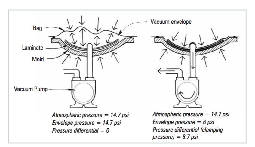
Aftwr that I will get everything ready to use the vacuum bagging
technique to form the composite. Vacuum bagging (or vacuum bag
laminating) is a clamping method that uses atmospheric pressure to hold
the adhesive or resin-coated components of a lamination in place until
the adhesive cures. This form of clamping has many advantages such as
even clamping pressure, control of resin content by controlling excess
adhesive in the laminate, resulting in higher fiber-to-resin ratios,
can customize any mold shapes and finally allows for a more efficient
laminating.
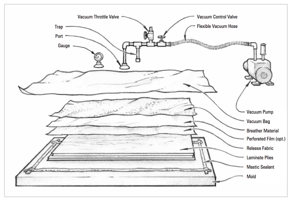
Here is a good link to help understand how the vacuum bag works:
http://www.westsystem.com/wp-content/uploads/VacuumBag-7th-Ed.pdf
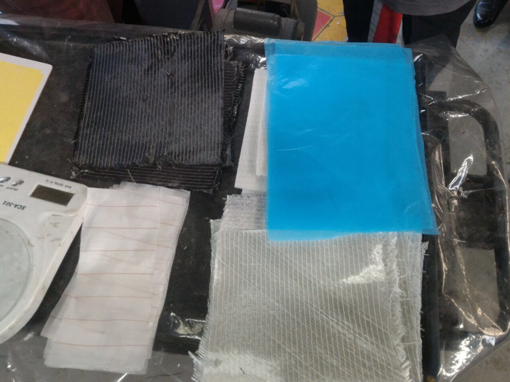
Below is a picture of some of the material but I didn’t end up using all of it:
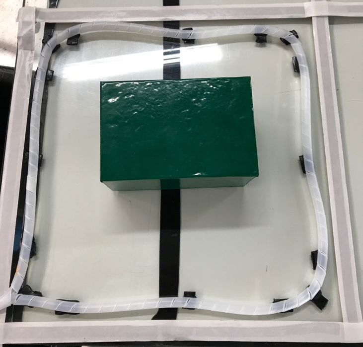
After cleaning the box, I got the glass table ready, I put the vacuum
bag sealant tape in an area that I thought were good enough to place
the vacuum bag later. I then sprayed the mold release spray onto the
surface of the box. After that I placed the (spiral tube) also used for
the vacuum bag and the breather cloth on top of the spiral tube. Lastly
attaching the vacuum hose to both the spiral tubing and the vacuum.
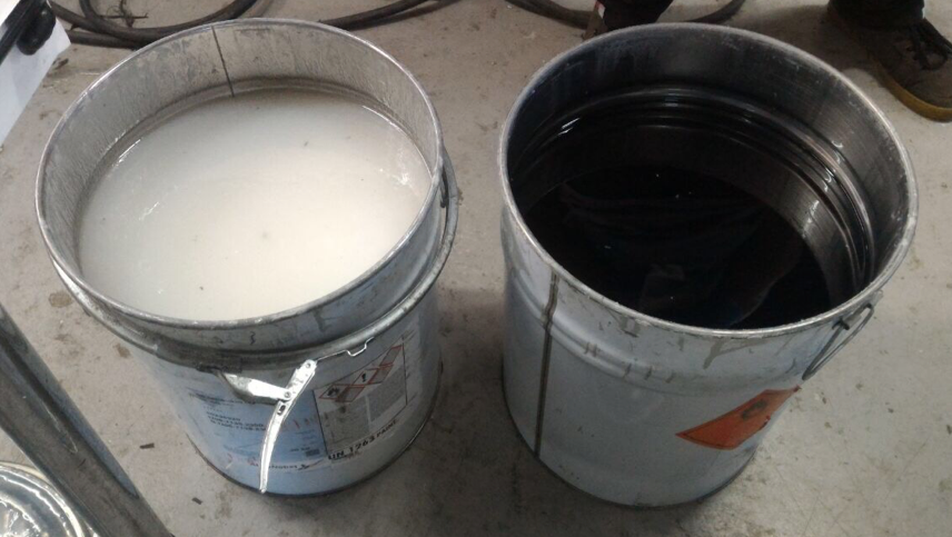
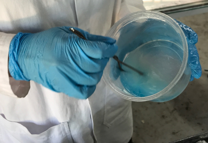
Now
it was time to mix the clear epoxy with the catalyst (Blue).
The ratio that I used was 100 R:75H. I could tell right away that it
was working because the temperature of the chemicals began to get hot
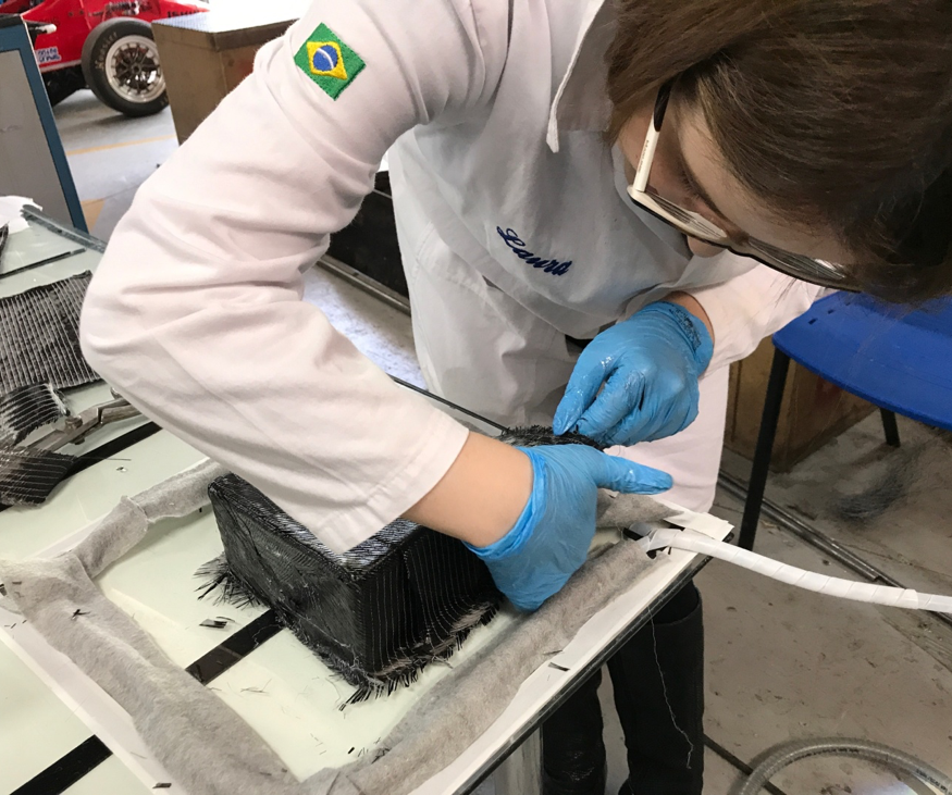
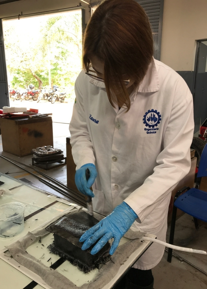
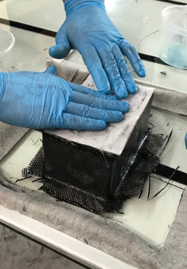
(exothermic reaction). Then I brushed the resin on to the green layer
and then I started placing the carbon fiber layer making sure to
packing it tightly against the sides. After that I brushed the resin on
top of the carbon fiber layer.To give more resistance to the box I put
a thicker carbon fiber layer at the bottom. Then I brushed the layer
with resin.
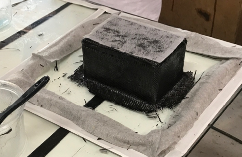
After that, I placed the release fabric layer
pressing it down to be as smooth as possible. Then I brushed another
layer of resin.
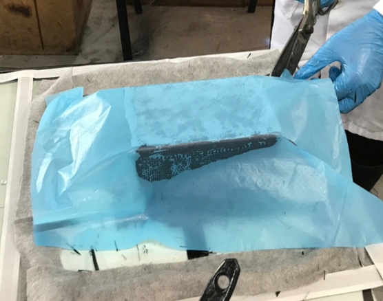
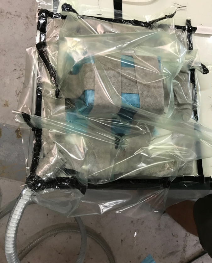
Then I placed a layer of blue perforated release film. Also, cutting
the corner so that it could mold tightly to the shape of the mold. Once
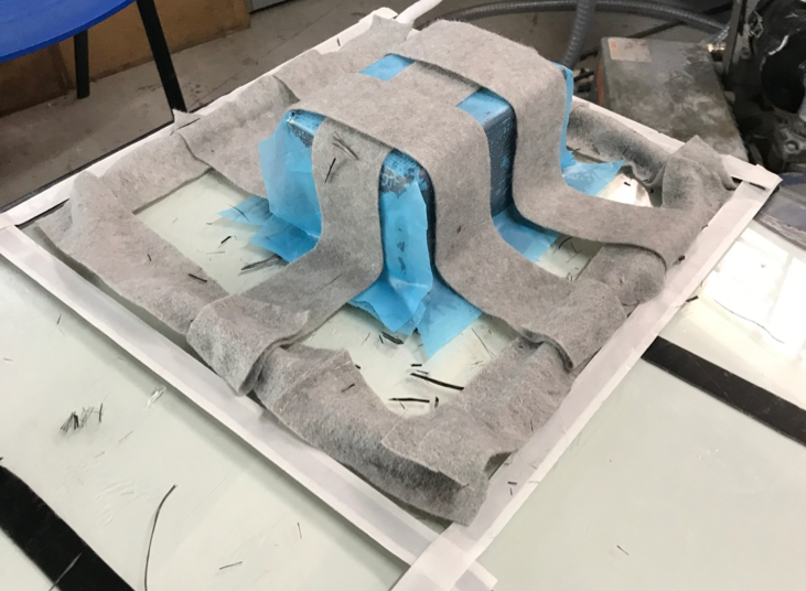
i did the previous placed the breather/bleeder cloth in the pater shown
in the picture below to remove the material later. Now it was time to
place the vacuum film on top of the designated area and seal it with
the vacuum bag sealant tape. Making sure that it is air tight.
Note: Leave
the Vacuum film baggy near the corners of your mold using the vacuum
bag sealant tape on the inside of the film running down all four
corners. This will create a skirt that will allow the vacuum film to
tightly hug the corners of your mold.
Video link of vacuum ceiling mold and composts:
https://youtu.be/KjCv4Oec-5c
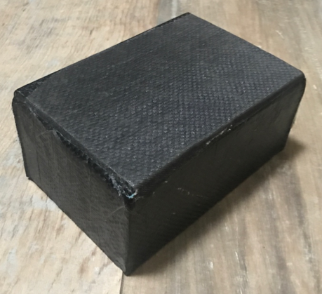
Final product once removed from the mold:
It came out extremely strong, water resistant, light weight. This
project really helped me understand what composites are and how they
are made. Strong enough to stand on.