Computer Controlled Machining
For this assigment, we have to:
- (DONE) Make something big (on a CNC machine).
All the files created for this assigment can be found on the link bellow:
Have you:
- Explained how you made your files for machining?
--> yes
- Shown how you made something BIG (setting up the machine, using fixings, testing joints, adjusting feeds and speeds, depth of cut etc)?
--> yes
- Described problems and how you fixed them?
--> yes
- Included your design files and ‘hero shot’ photos of final object?
--> soso
Designing the Oject
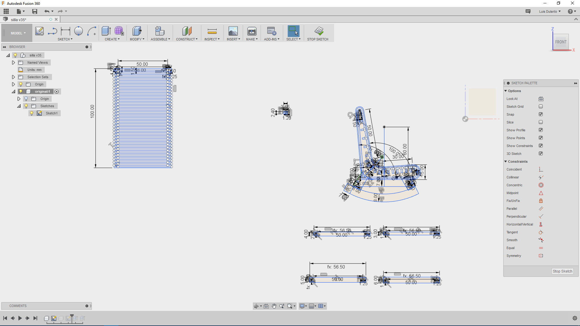
I worked with Fusion 360 for designing the object planes. The basic Idea was to design a rocking chair
This are the steps I did for this task:
1. First, I created a new component, and did a sketch of all the principal rocking chair parts in one sketch. This sketch contained a lot of construction lines which I needed to delete for milling my object.
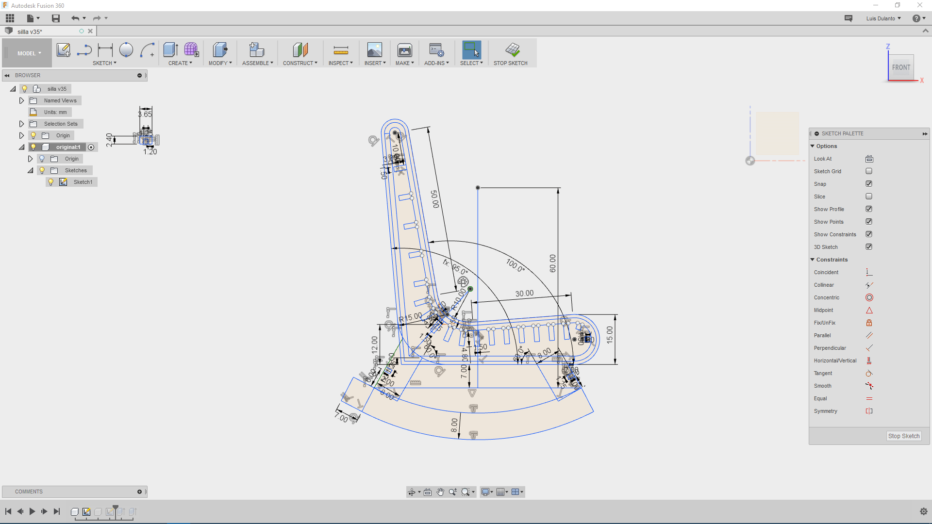
2. Then, I created a copy of the component by right clicking over the component and selecting copy and pasting it as a new component (this is done by right clicking over the principal component and selecting paste as new component).
3. I used the trim tool to delete all the construction or auxiliar lines in the sketch.
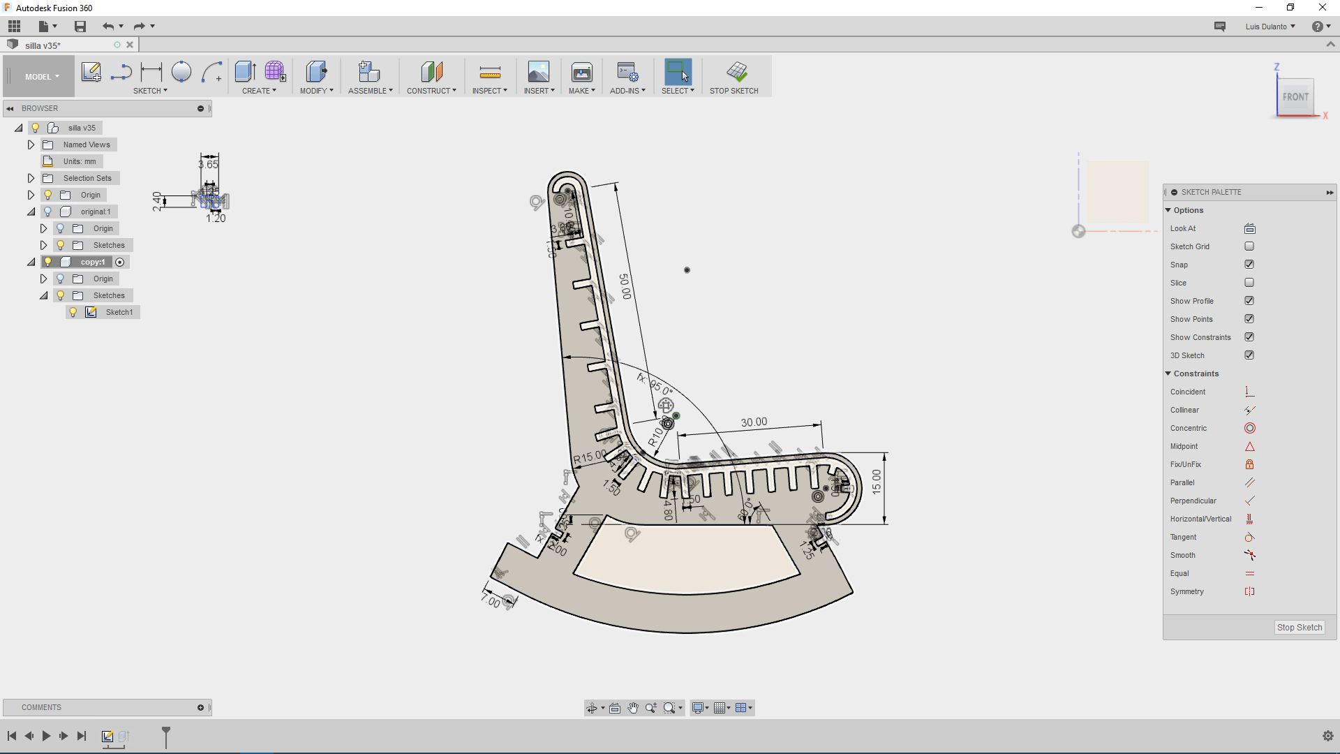
4. Then I right clicked over the new component and selected export as dxf.
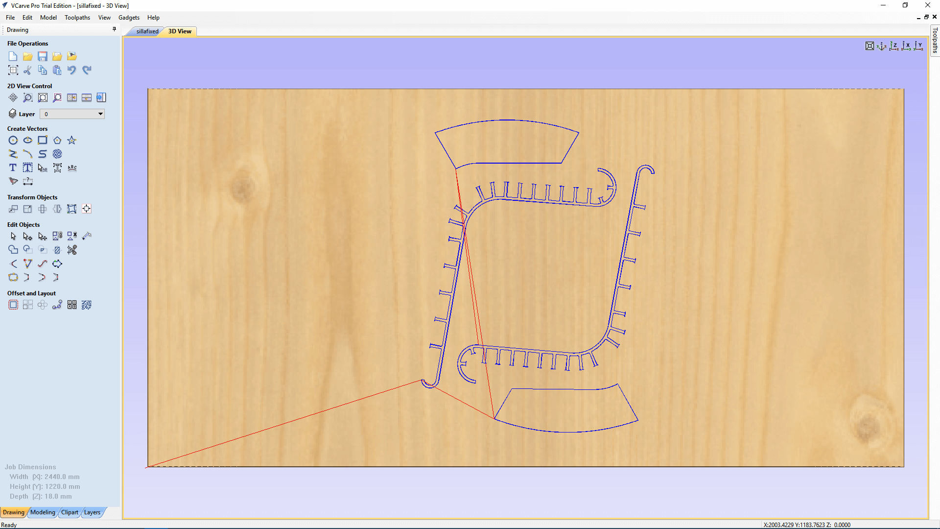
Preparing Planes For Being Milled
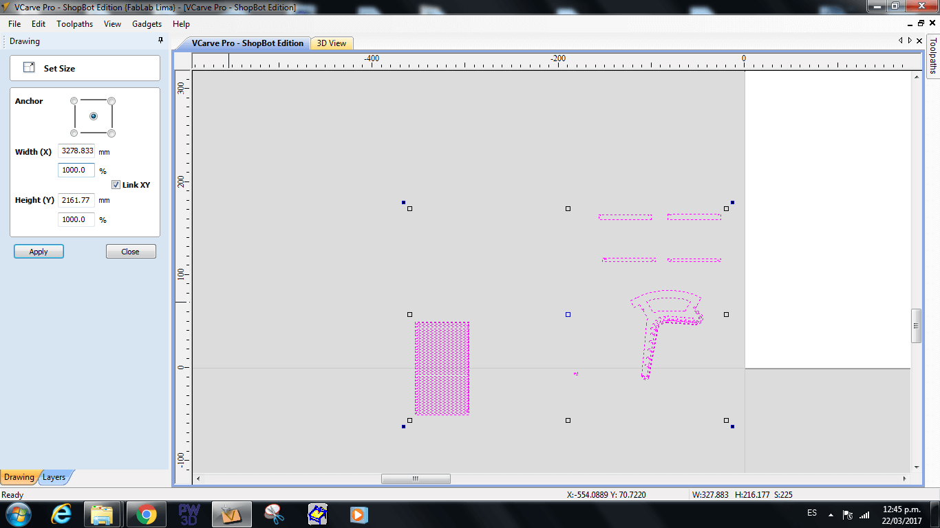
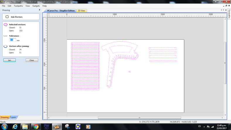
This are the steps i did for for this task:
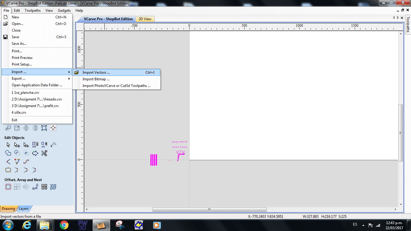
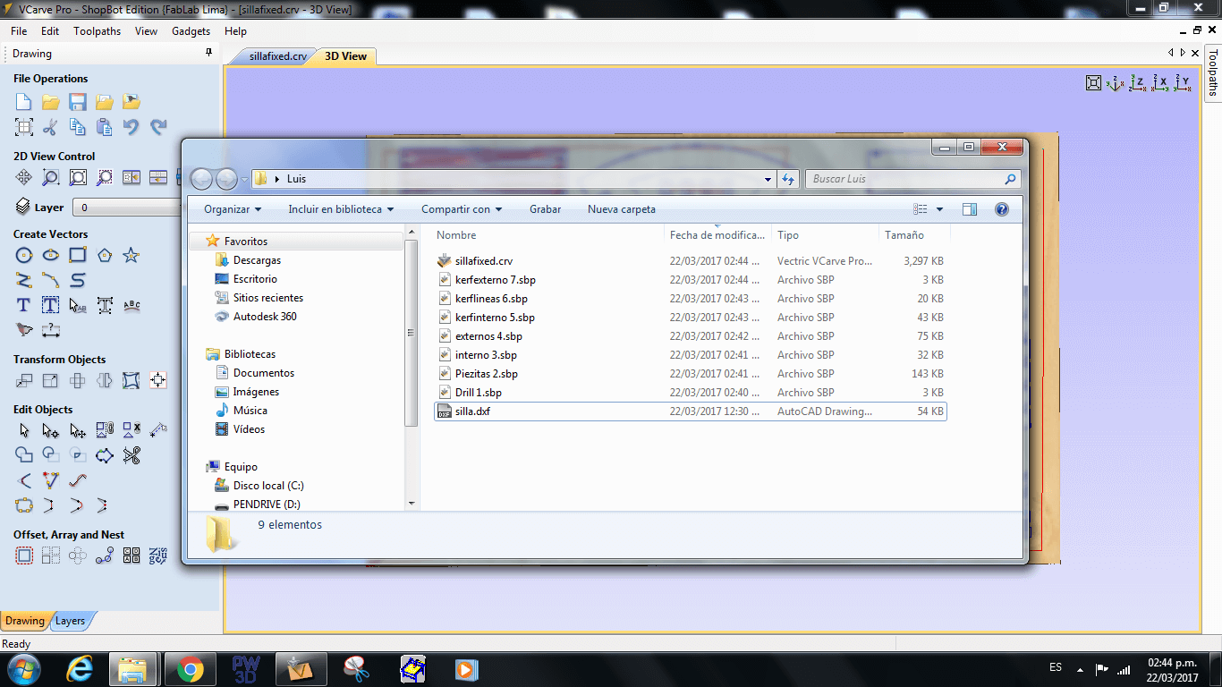
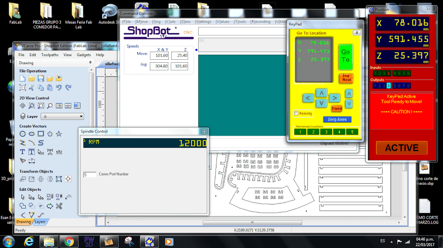
1. First I oppened the Vcarve software created a new document and imported my design by clicking on file import-> import vector.
2. Since my model was done in cm instead of mm, I scaled up by 10 my design by clicking on the scale tool and changing the scale percentage from 100% to 1000%.
3. Then, I selected all the sketches and clicked on the join tool for completing blank spaces between some sketch lines.
4. Since the miller can not make sharp internal cuts, I added ears (with a diameter equal to the mill diameter) to all the internal cuts of the model, this is done by clicking on the fillet tool. The type of ear I used was the T-Bone Fillet.
5. Once I added ears to all my models, I created copies of the eared sketches for completing the planes of the object.
6 I rearranged the objects into a 2440X1220 document.
7. Since the board was going to move when it was milled I needed to fixed it with screws, so i added circular holes to the design for making a small perforation on the places were i was goint to put the screws. This holes were done with the circle tool and a had a diameter (6.4 mm) a little bit bigger than the mill (1/4''= 6.3175mm).
8. Then, I selected all the hole and clicked on the drill tool, I left the depth of the drill as 3mm, named the profile and calculated the drill path.
9. After that, I selected all the smallest pieces and cicked on the profile tool.
10. I setted the depth of the cut as 13.2 mm (lefting one extra milimeter for my board of 12.2 mm) and the type of cut as external.
12. I added some tabs to all the pieces by clicking on edit tabs, this tabs had a depth os 3mm and a wide of 5mm.
13. Then, I named the profile and clicked on calculate to get the milling path.
14. Then, I selected all the internal cuts excepting the ones on the kerf, and clicked on 2D profile. I left the depth of the cut as 13.2 mm setted the type of cut as internal and did not add tabs.
15. Then I named the profile and clicked on calculate to get the milling path.
16. Then I selected all the external cuts excepting the small pieces and the ones on the kerf and repeated the steps from 11 to 13.
17. After that, I selected all the internal cuts in the kerf and reppeated the steps from 14 to 15.
18. Then, I selected the lines on the kerf and clicked on on profile. I left the cut depth as 13.2 mm and the type of cut as "on" (means over the line).
19. I added between four and five tabs per line and setted the tab depth as 5 mm and a width of 5mm.
20. Then I named the profile and created on calculate to get the millint path.
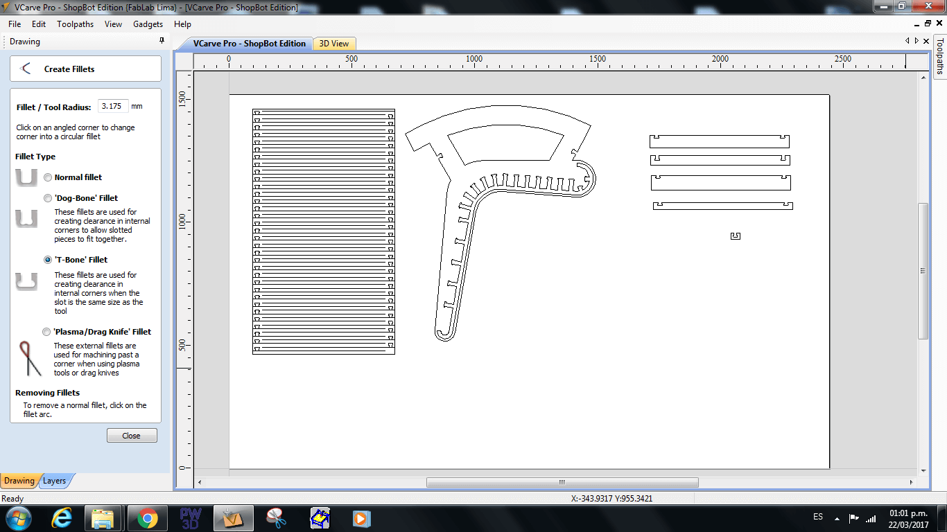
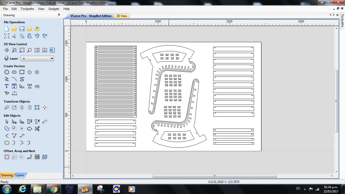
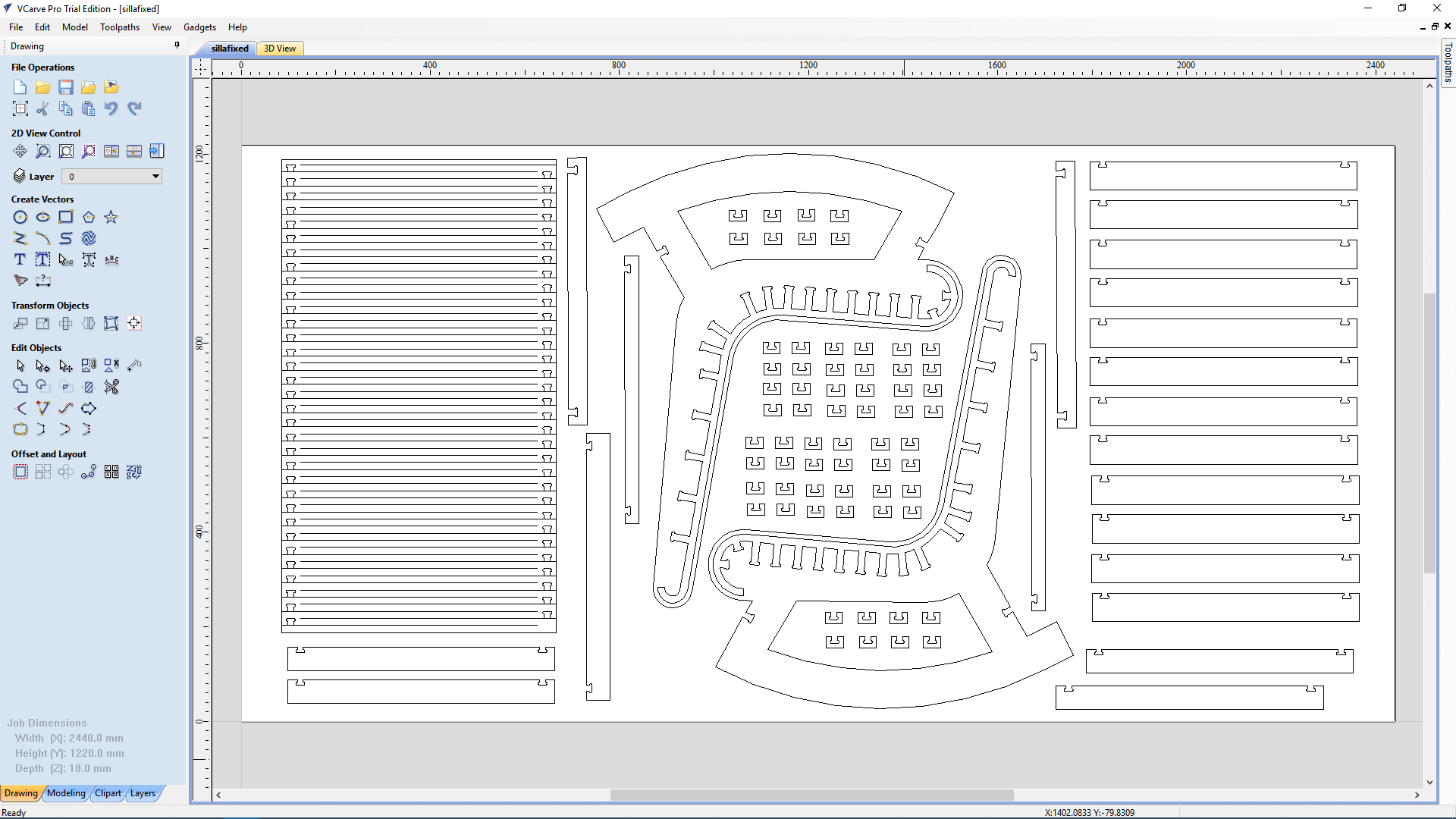
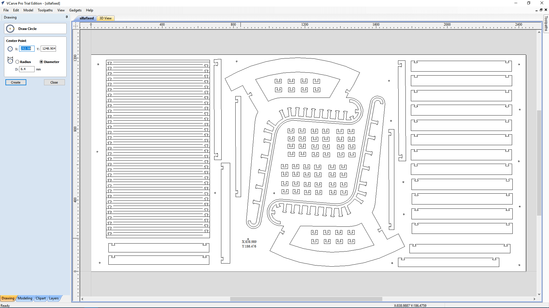
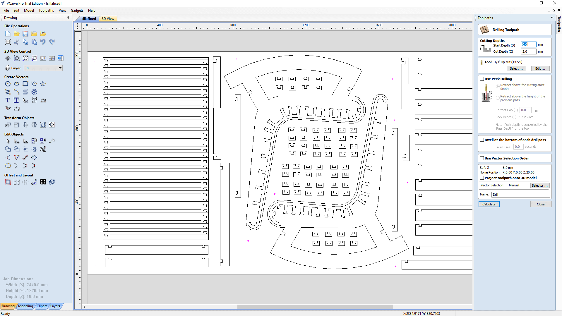
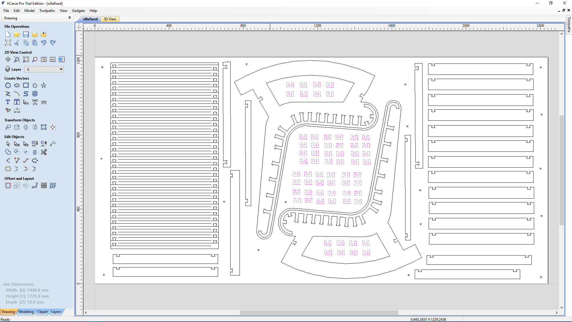
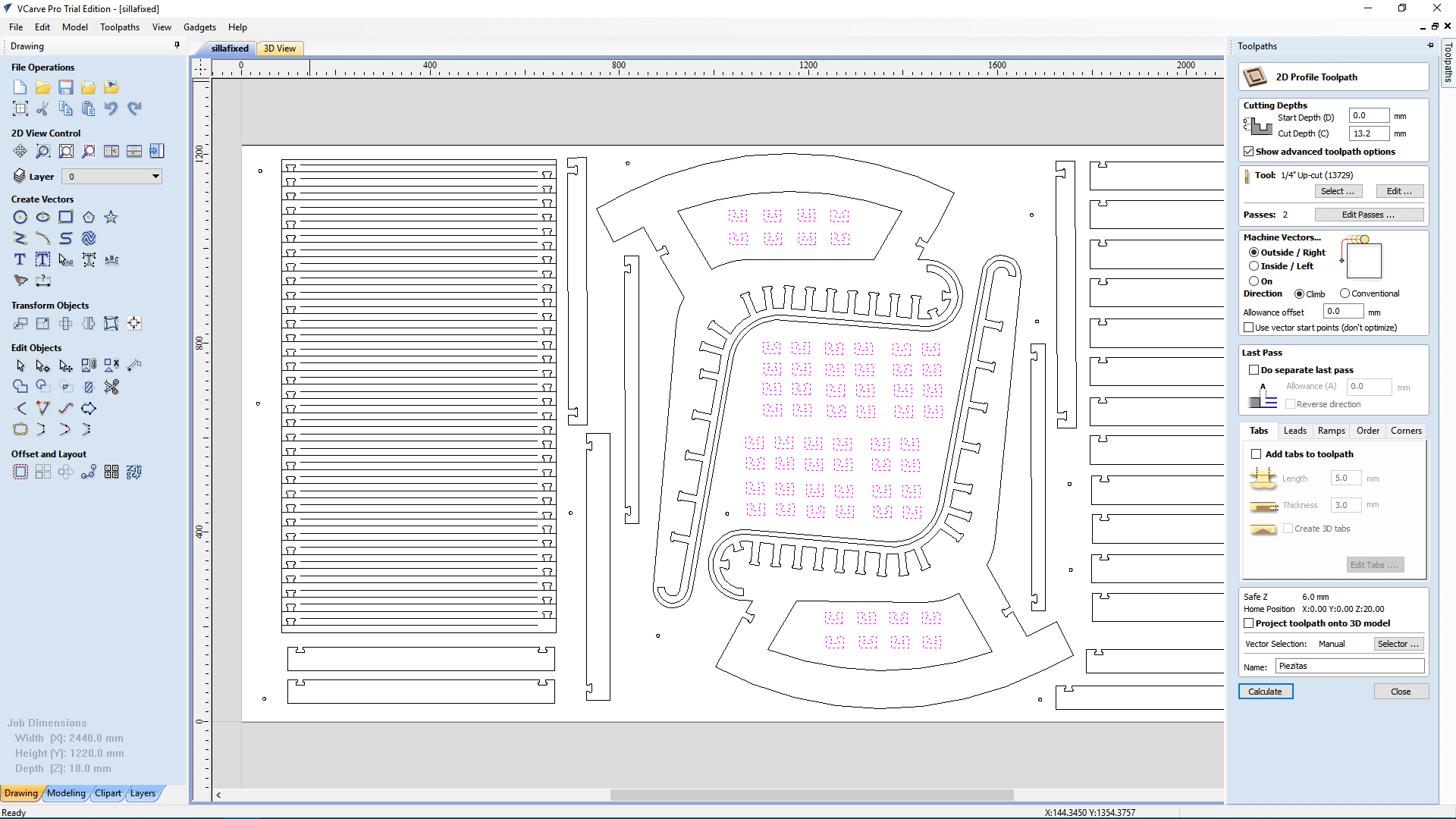
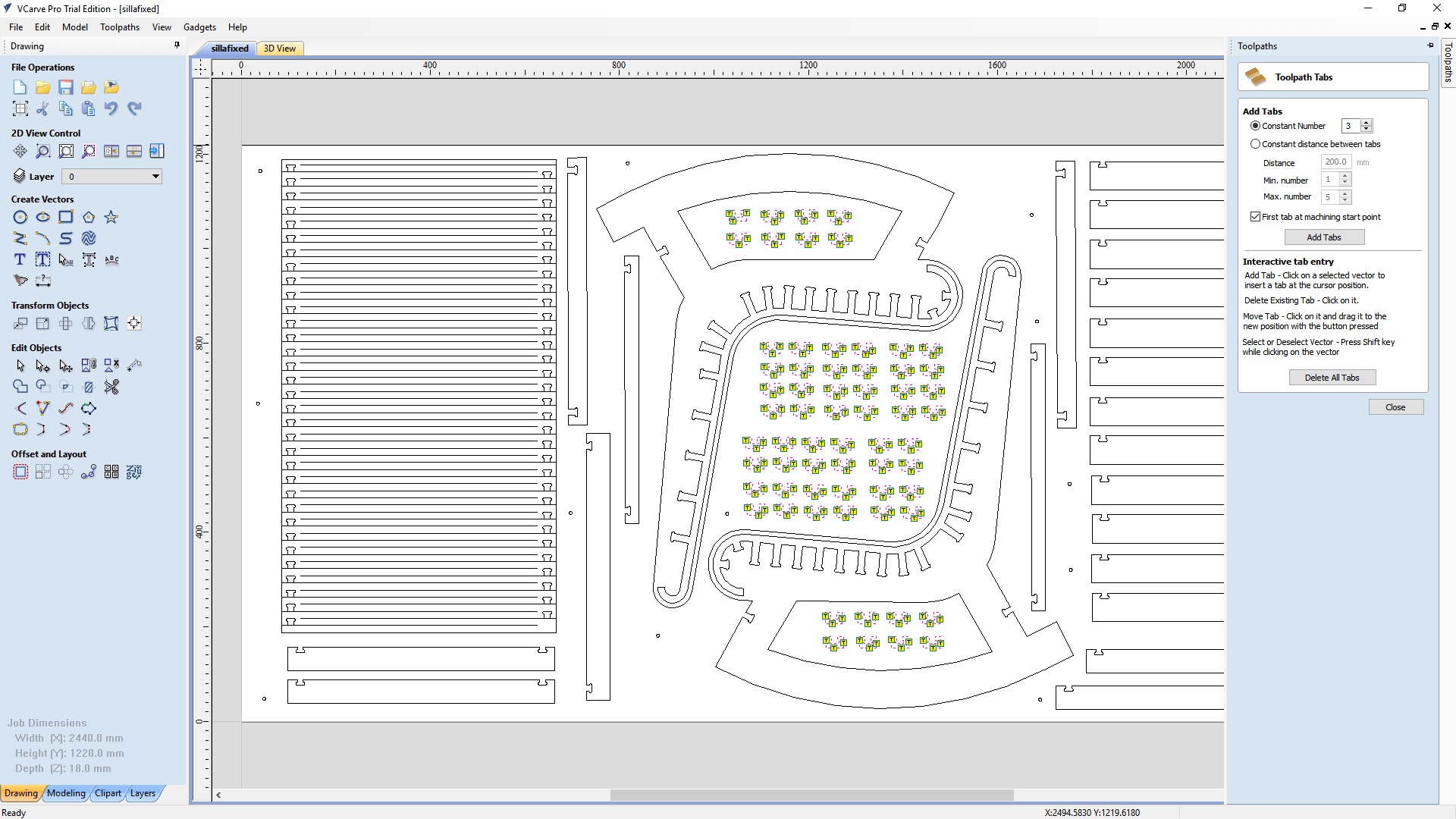
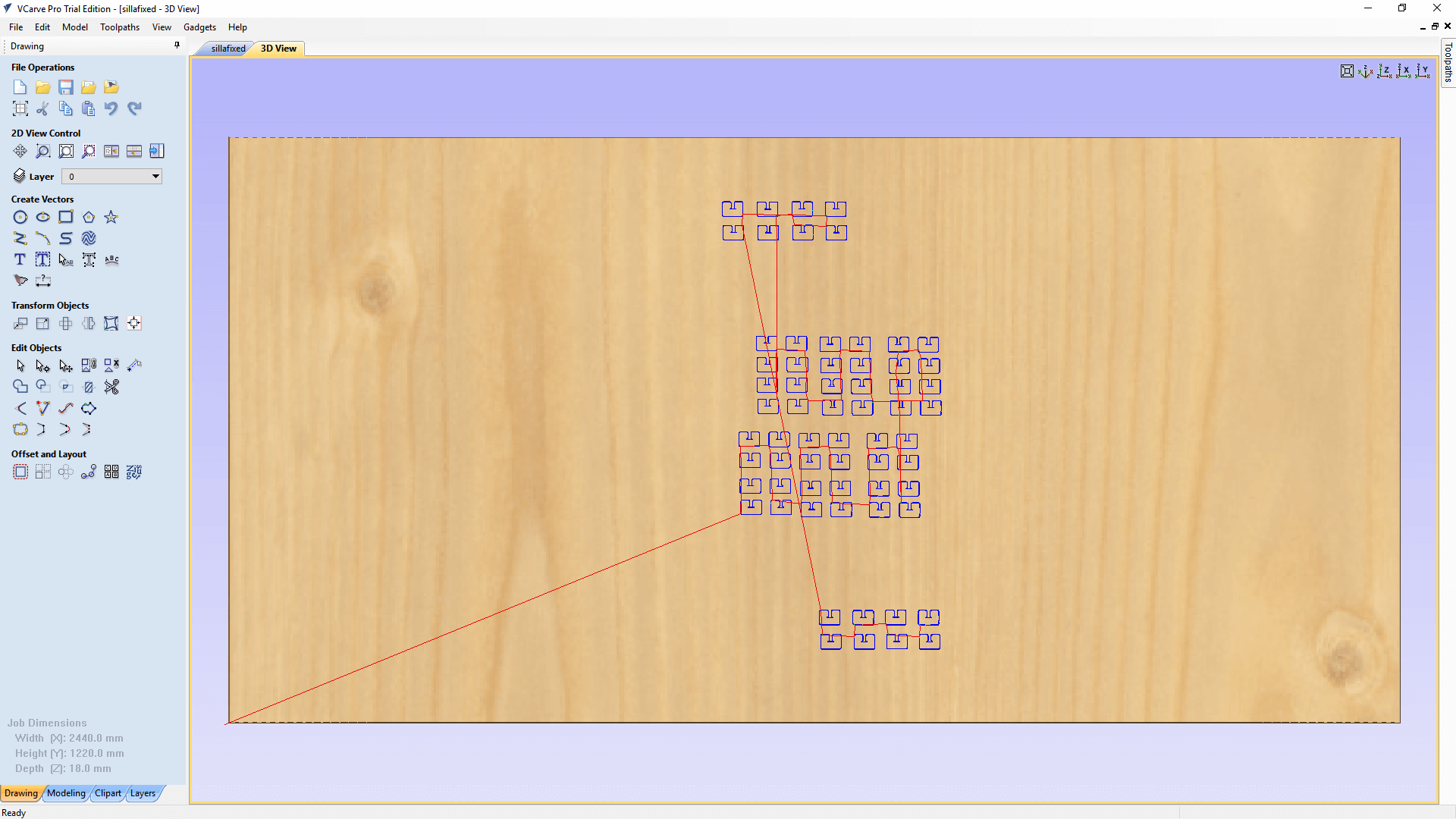
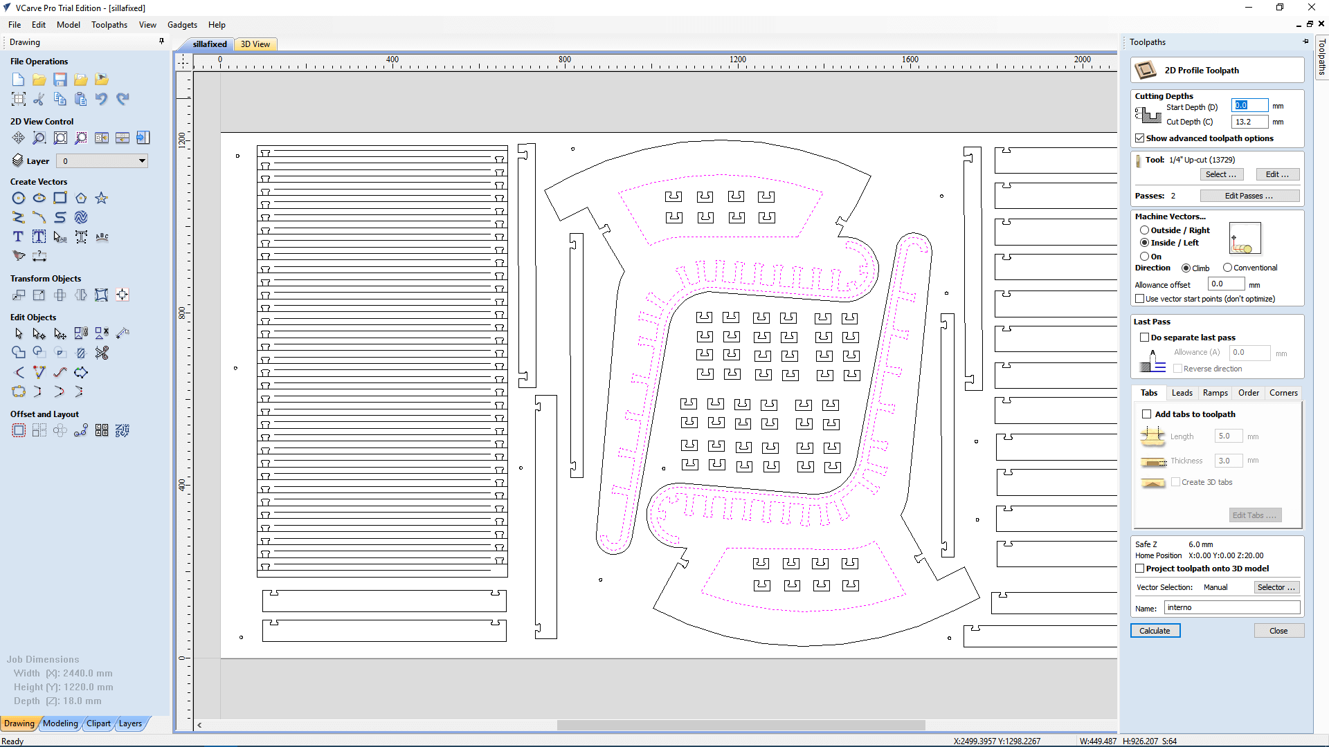
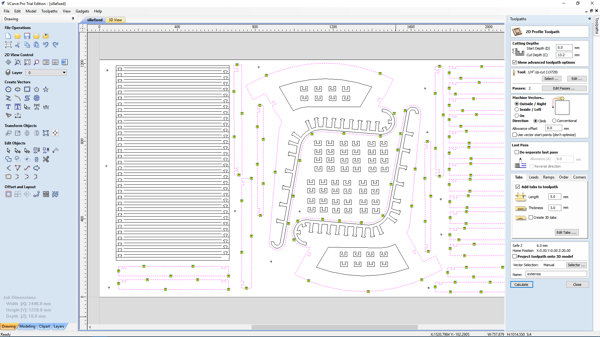
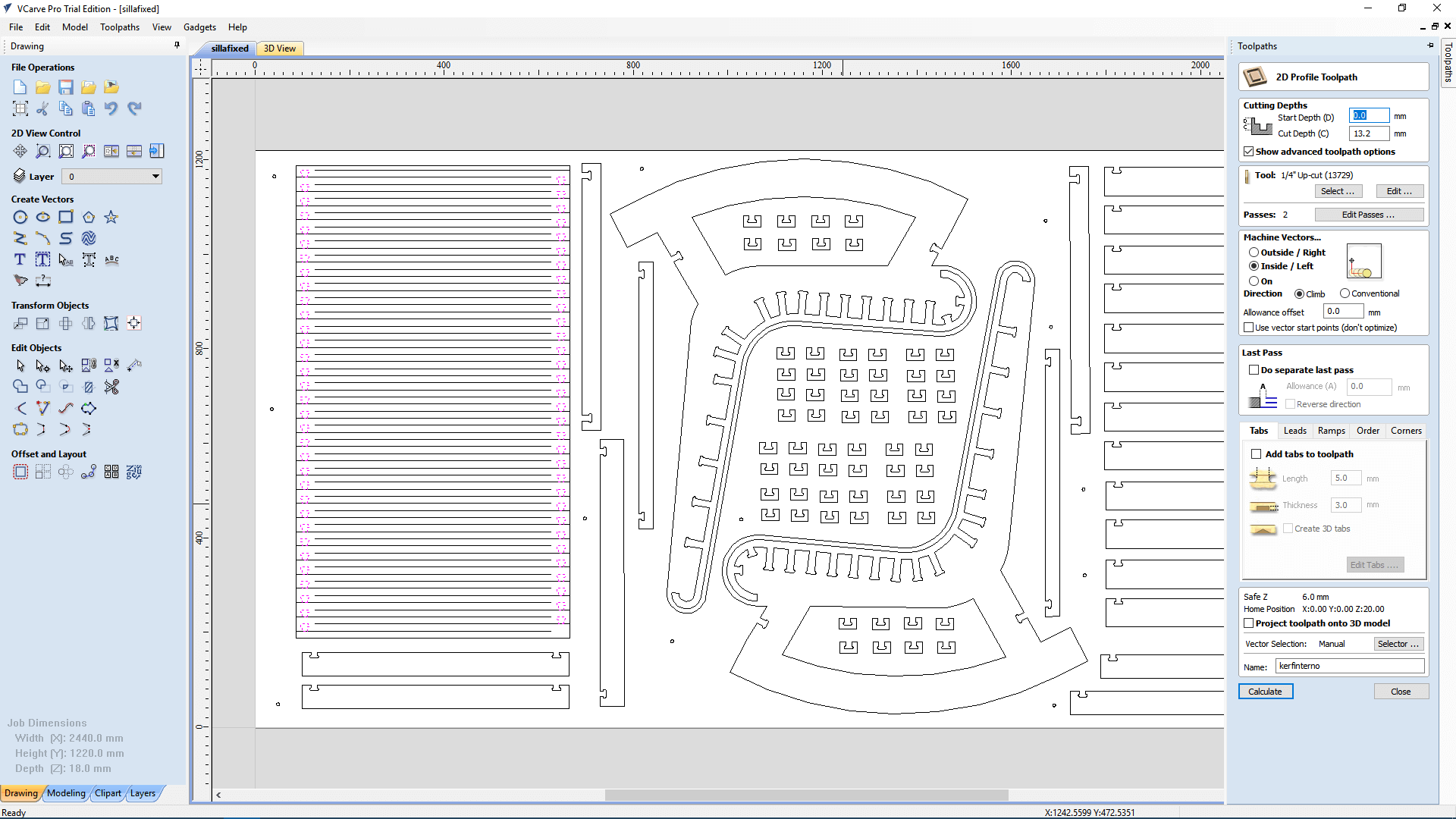
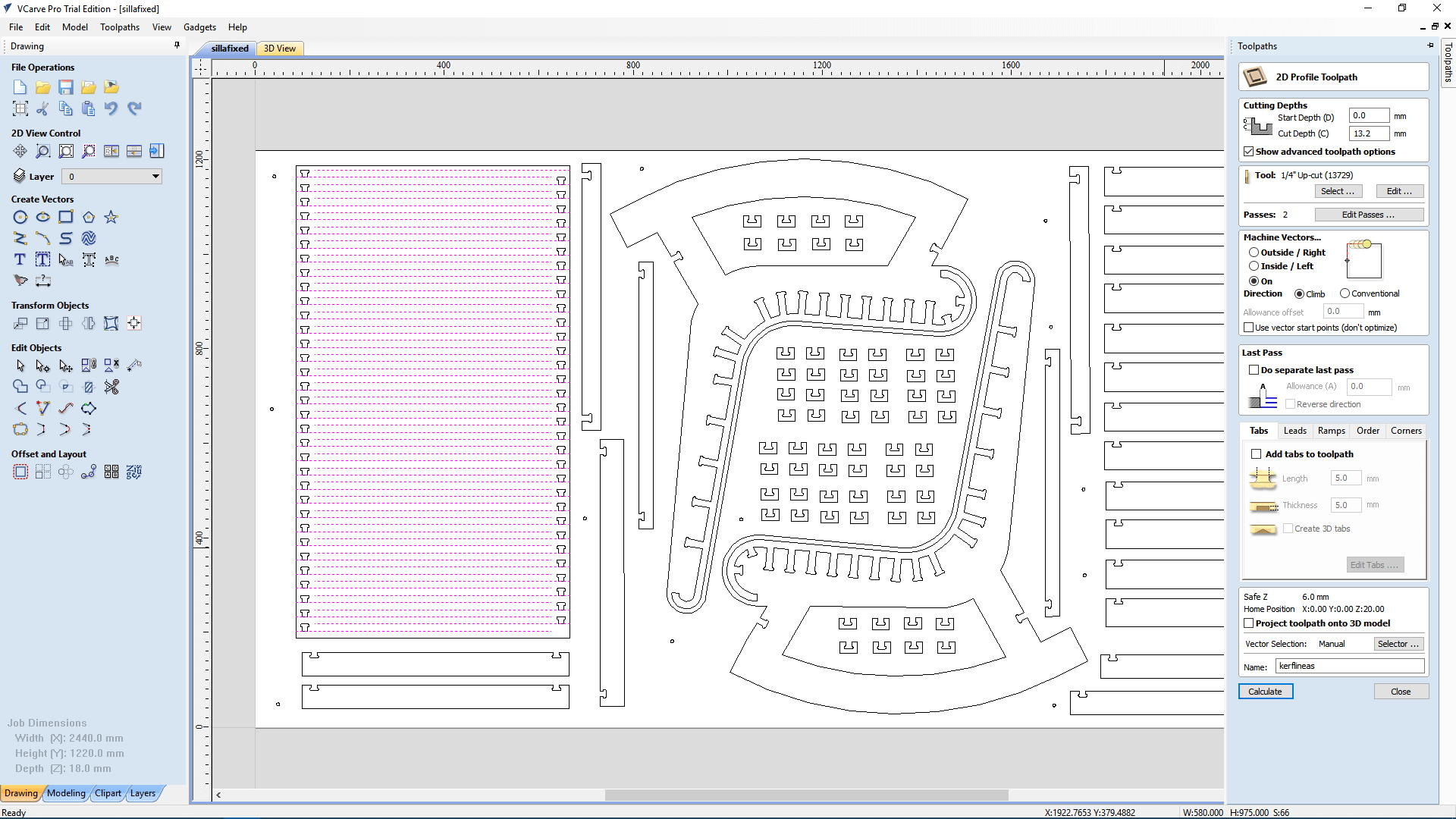
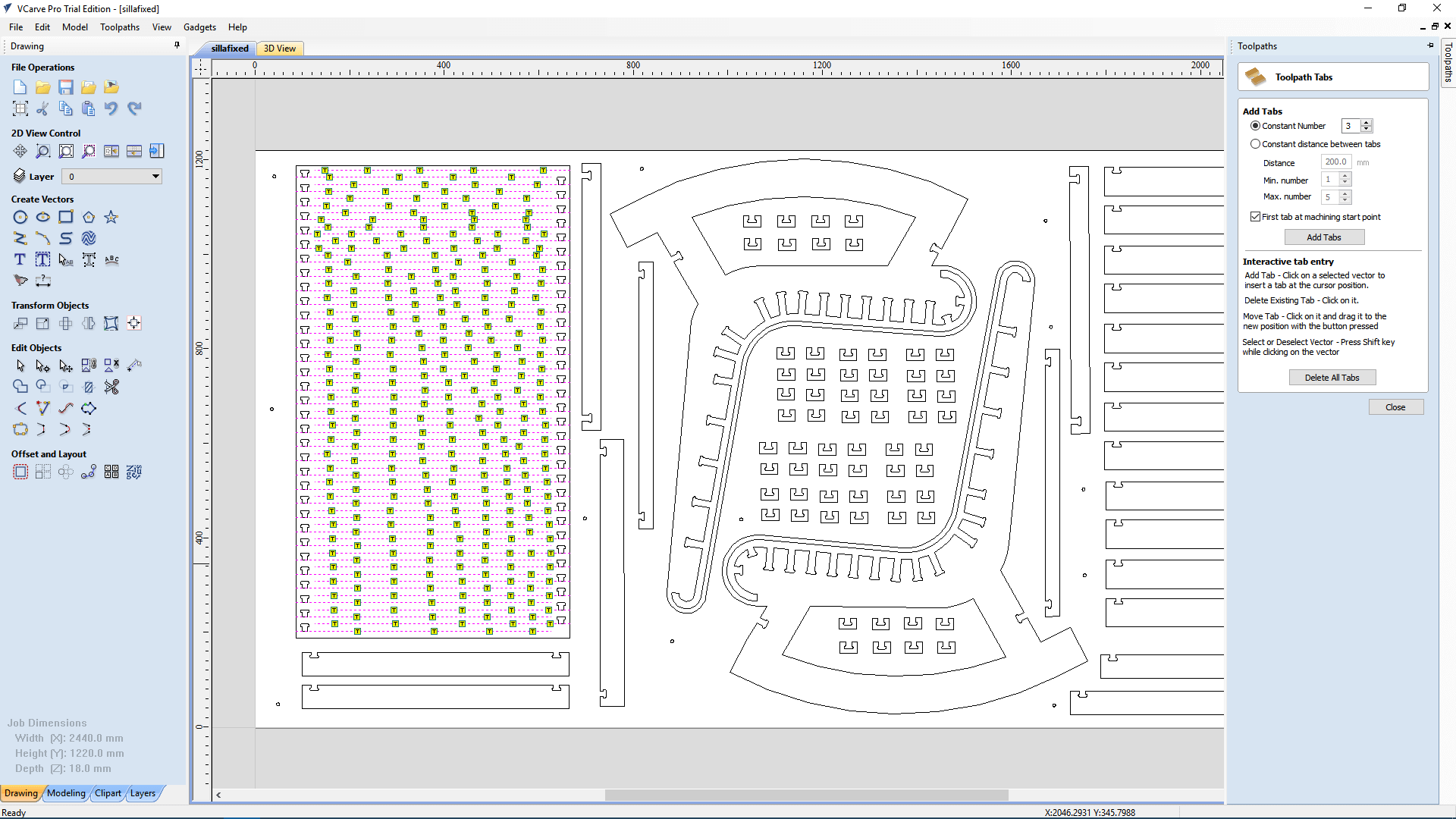
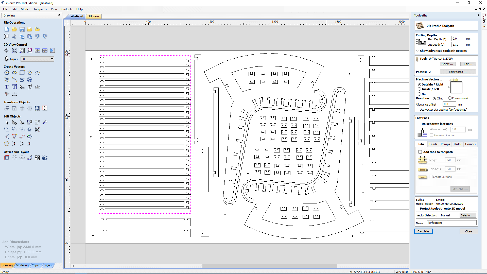
21. I selected the external cut of the kerf and added tabs to every sub.piece of the kerf.
22. Then, I saved each milling path by clicking on save toolpath and selecting only that path.
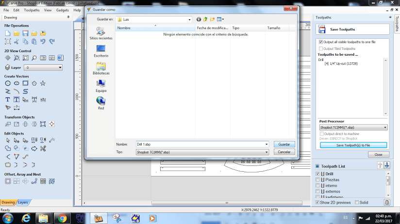
23. Finally, I clicked on save and named the milling path with a number which represents the order of milling.
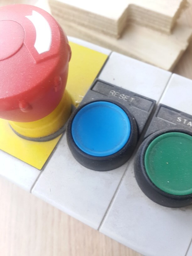
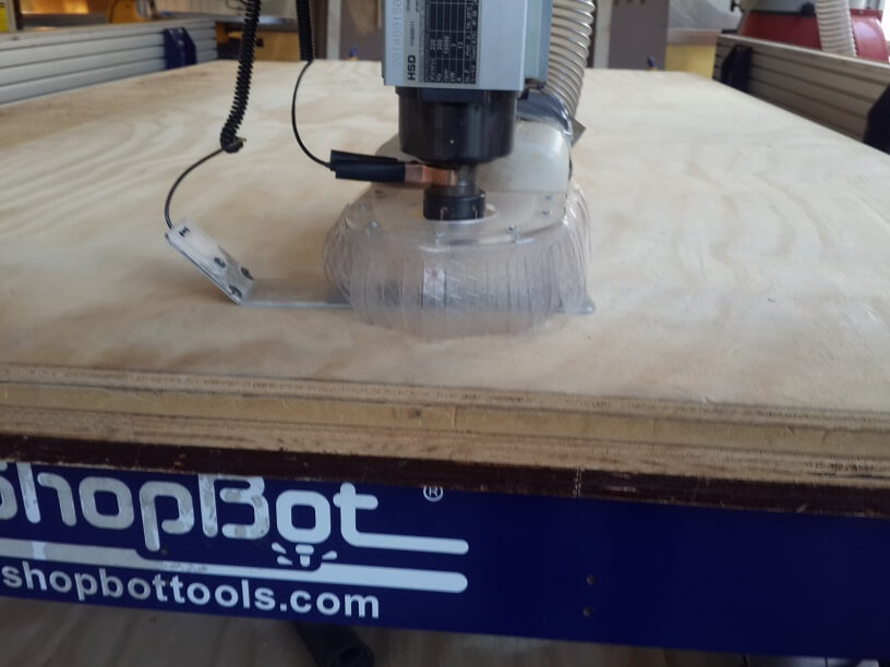
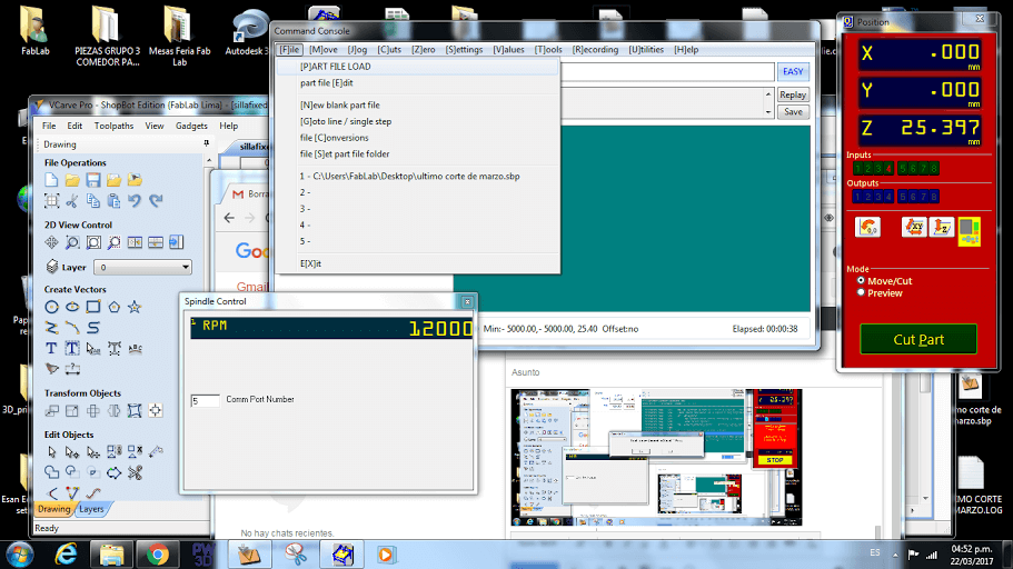
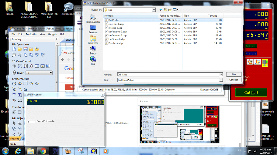
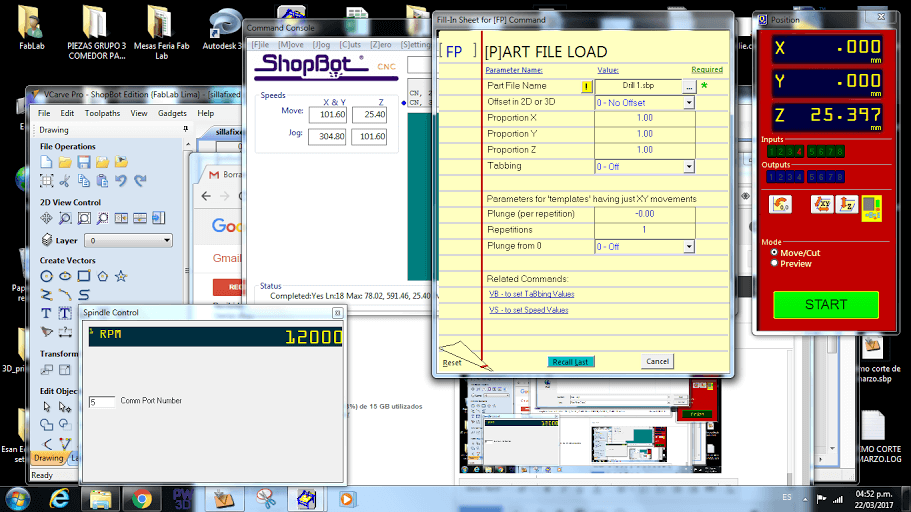
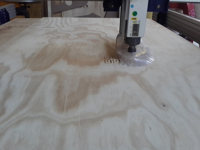
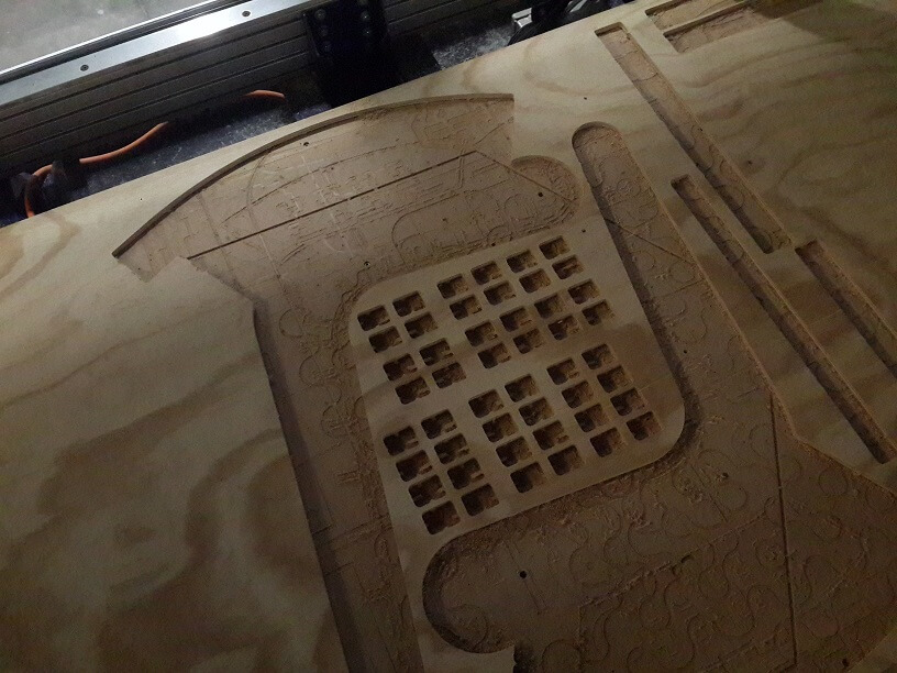
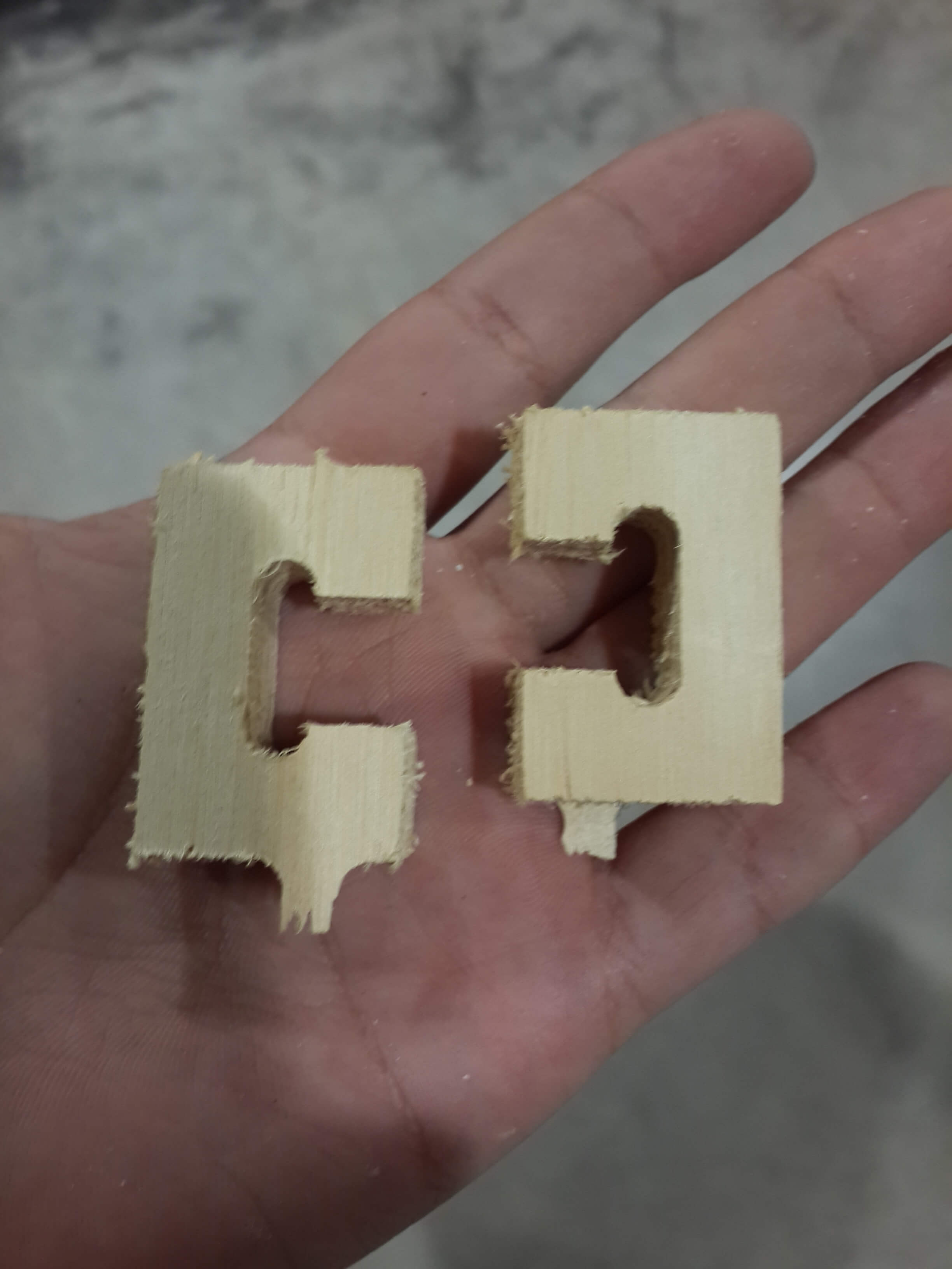
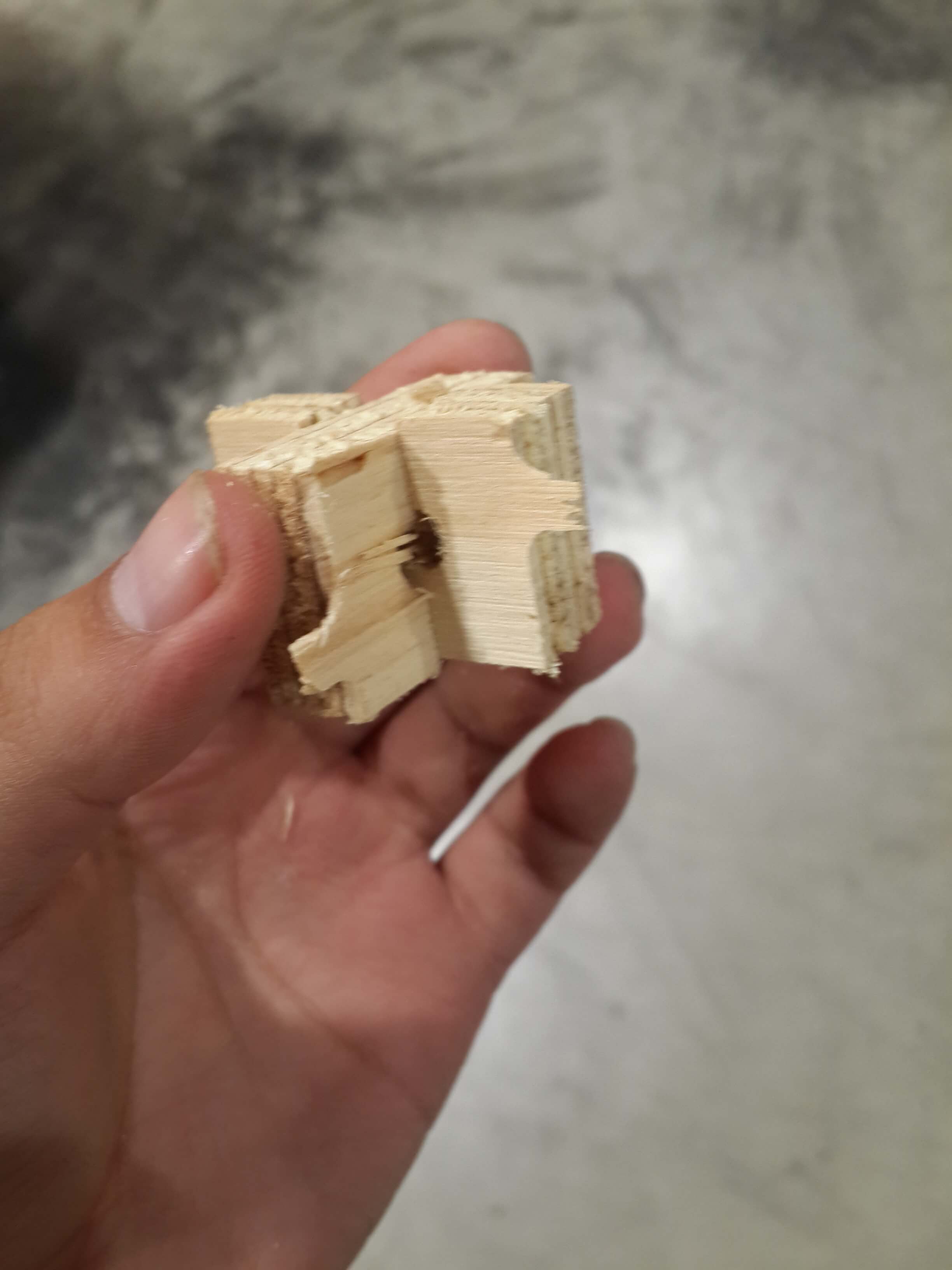
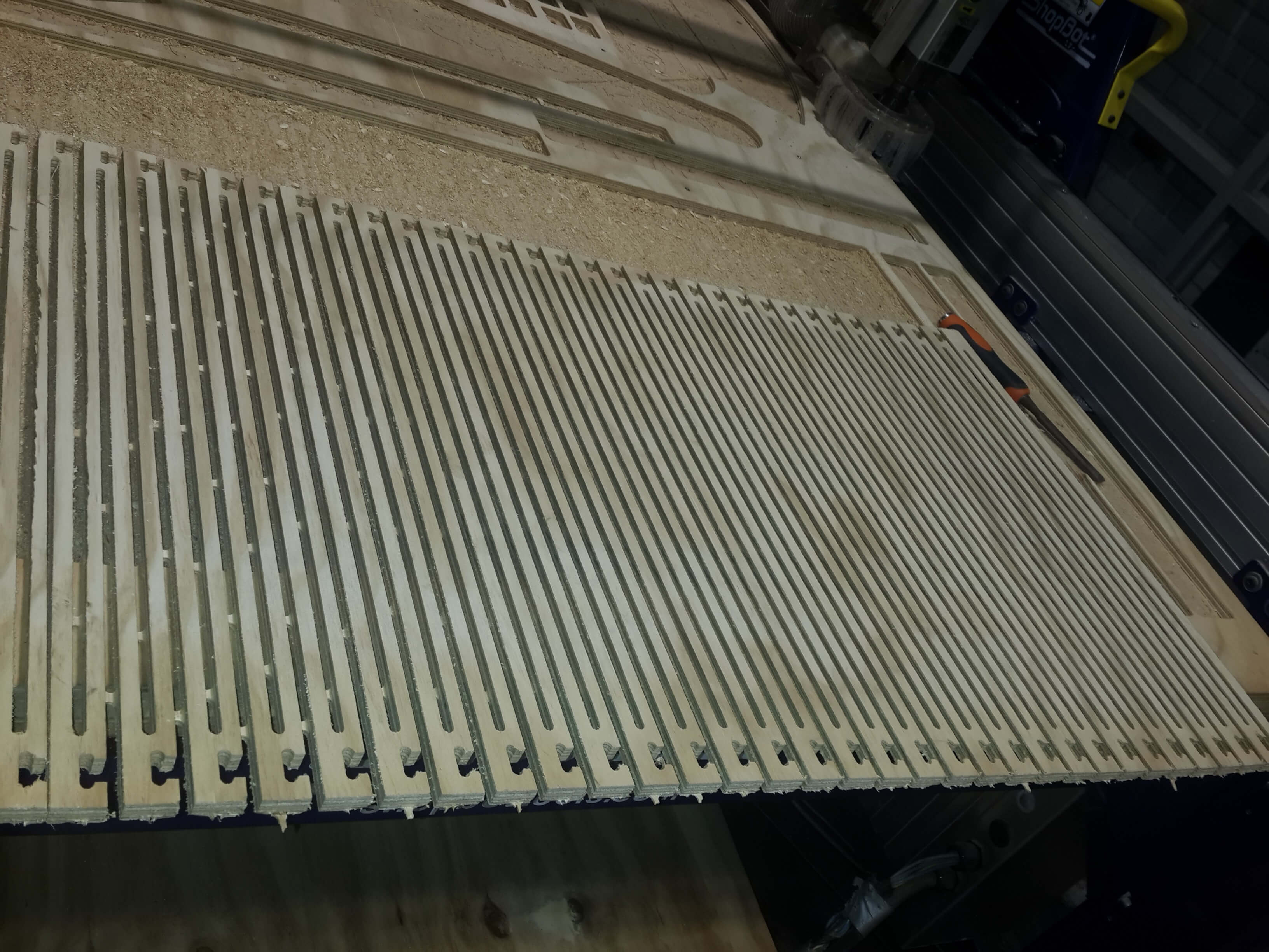
Just to mention, I had many problems when trying to mill the piece designed for kerf bending. At a begining I put only 3 tabs to each line of the design of this piece with a width and height of 5mm x 3mm, however this was not enought. Since when I tried two mill only three consecutive lines of the design, the tabs broke and the wood started to vibrate forcing me to stop the machine. So I fixed this by adding two to three more tabs to each line (having 5 or 6 tabs per line) and giving it a 5mm of height to all of this tabs instead of 3 mm.
Also, when I tried to mill, the machine stopped suddenly like three times and I got a message on the pc saying that it was disconnected. I am not really sure about this, but it seems that the auditory protectors that were on the shopbot were hitting a cable connected to the miller, so I retired and the machine never stopped again. When this issues happened I just recalibrated the machine and resent to mill the pieces that were incomplete because of this sudden stops.
In general, this were the steps I did for milling all the pieces:
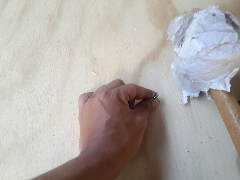
1. I putted the board over the shopbot and fxed it with some presses.
2. I turned on the Shopbot by turning the red switch to on, and also turned the motor by turning the key one step clockwise.
And made sure that the usb cables were conected to the notebbook.
3. I openned the Shopbot Software, and pushed the reset button on the techpendant.
4. And then, clicked on the yellow button to open the manual control of the shopbot.
5. I moved the mill to a flat surface of the board, puetted a metal under it and attached a cocodriled connector to it.
6 Then I clicked on "Z" to calibrate the shopbot on the vertical plane and then retired the cocodrile and the metal plate.
7. After that, I clicked on xy to calibrate the Shopbot on the horizontal direction.
8. Then, I loaded the drill path, on the Shopbot software and clicked on start.
9. A warning message appeared indicating that i shoud push the start button on the techpendant, so I pushed it and the mill started to spin.
10. Then, I cicked OK on the warning message and the Shopbot started to make the drilling holes.
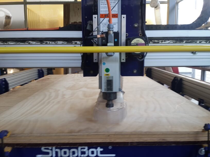
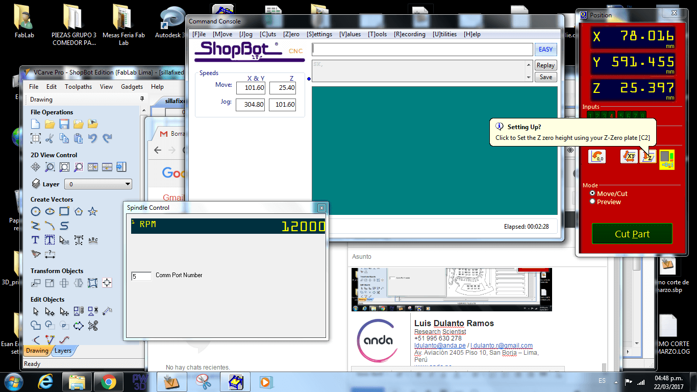
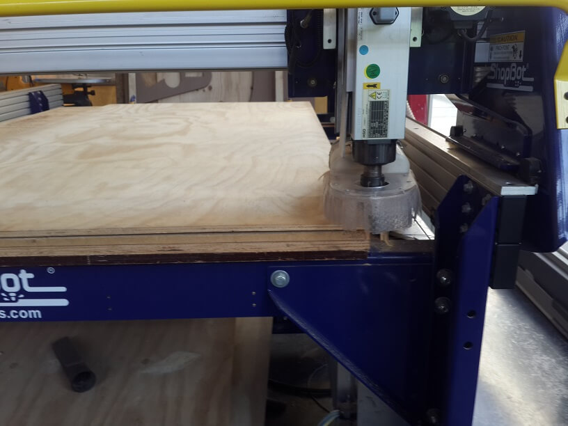
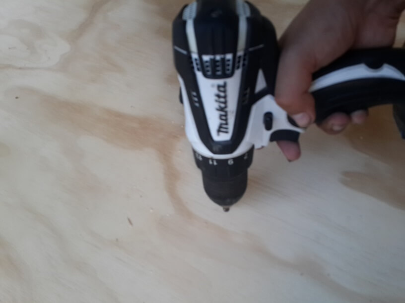
11. After that, I fixed the triplay board to the shopbot by using some screws and a driller.
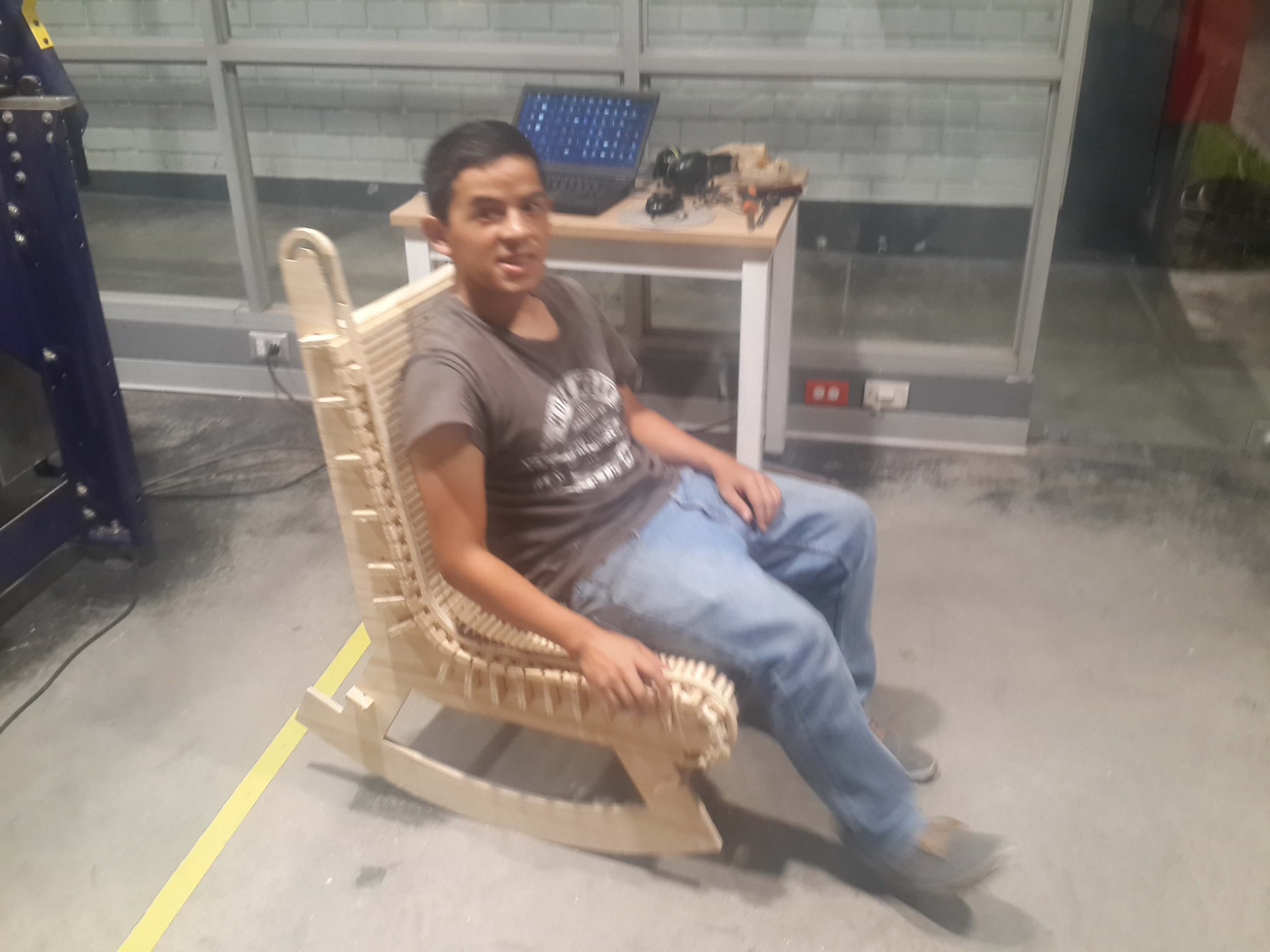
12 Then, I turned on the compressor and putted the ear protectors.
13. Once again, I loaded the next milling path, which were a couple of small pieces, on the shopbpt software, clicked on start, pushed the start button on the techpendant and clicked OK on the warning message.
Once the machine finished, I retired this pieces, checked if the cut pass through all the piece and tested if the width of the cuts was correct so that they fitted perfectly, and since they fitted well, I proceeded milling all the small pieces and the rest of milling paths.
14. I repeated step 13 for every milling path.
Final Result
Finally I a assembled all the pieces
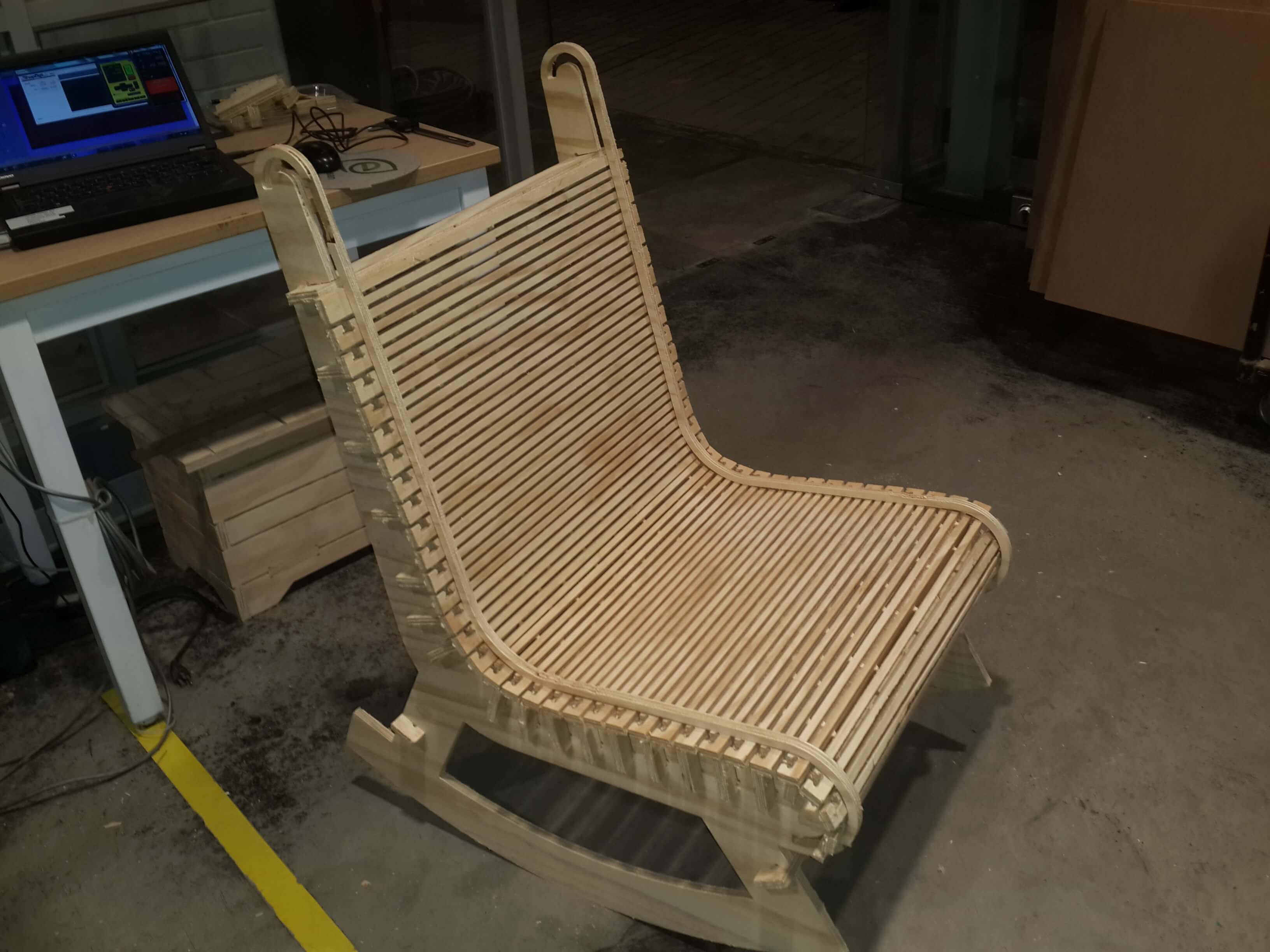
And tested the rocking chair with myself.