Electronics Design
For this assigment, we have to:
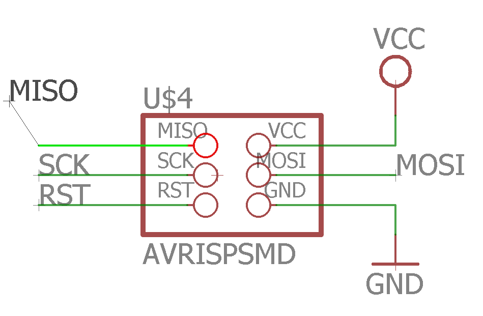
- (DONE) Redraw the echo hello-world board, add (at least) a button and LED (with current-limiting resistor), check the design rules, make it (if you have time this week, test it).
- (DONE) optional: simulate its operation. Measure its operation
All the files created for this assigment can be found on the link bellow:
---> DOWNLOAD FILES<---
Have you:
- Shown your process using words/images/screenshots?
--> yes
- Explained problems and how you fixed them, including how you worked with design rules for milling (DRC in EagleCad and KiCad)
--> yes
- Programmed your board?
--> yes
- Described the programming process/es you used?
--> yes
- Included original design files?
--> yes
Designing The Circuit
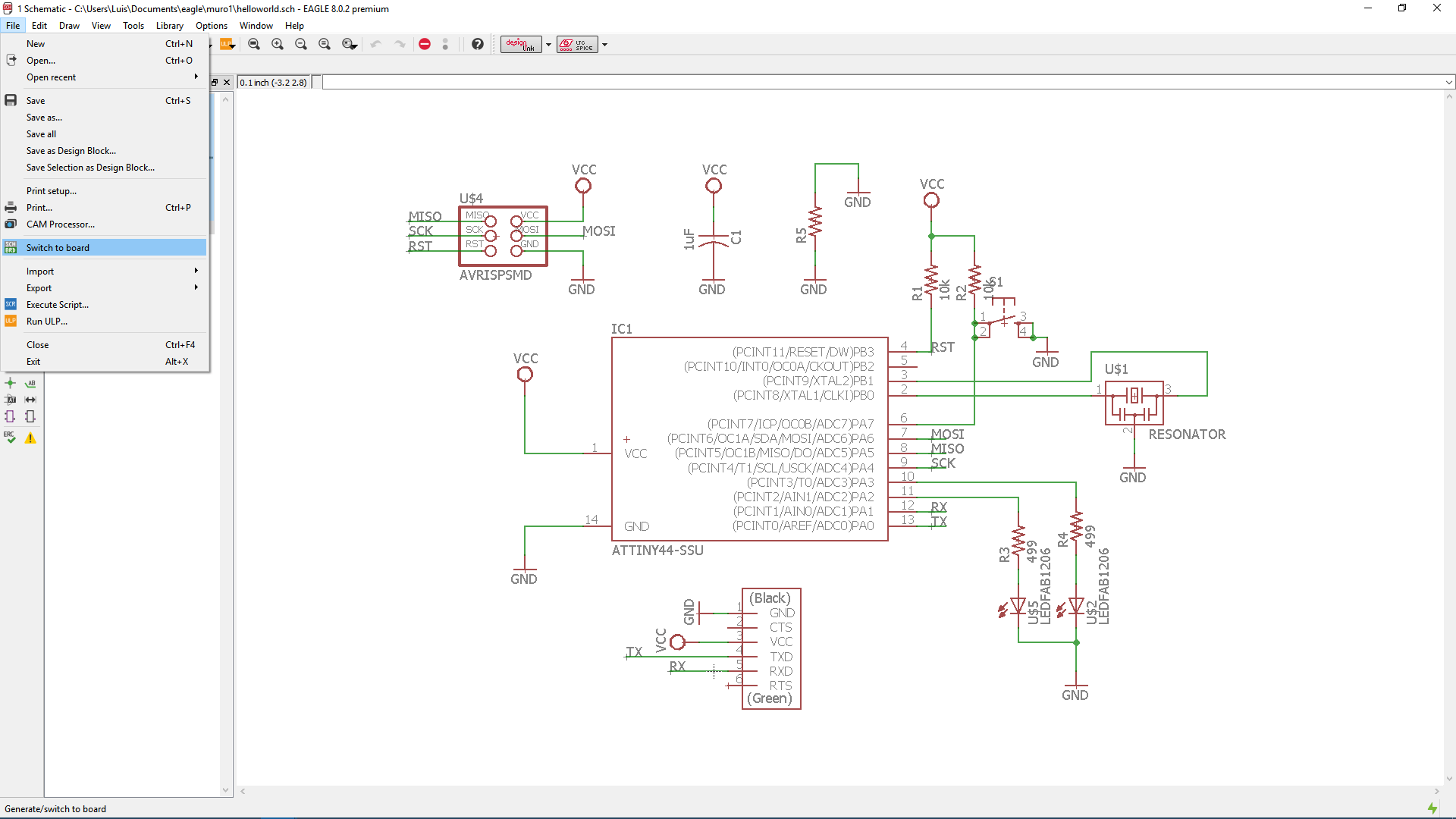
We were told that we must add at least one switch and one led in the circuit design. So i added two leds and a switch. Since i did not had the smd led data sheet i assumend that they could deal with a 10 mA current and knowing that the Attiny 44 could give up to 40 mA per pin I decided that a current of 10 mA should pass through each led and that the source power of a led should be one of the Attiny pins, since they could provide much more than 10 mA.
The output voltage of the Attiny 44 is either 0 or 5 volts, So if i wanted 10 mA on a pin I need to regulate the current on the output pin by putting a resistor in series with the led. I assumed that the drop voltage on the led was 0.7v when turned on (maybe it was much more), so this would mean that there was at most a drop voltage of 5v - 0.7v = 4.3v on the resistor and a currect I of 4.3v/R Ampere through the resistor, where R is a variable that represents the resistence of the resistor. And since the current that passes through the resistor is the same that passes through the led, all what i needed to do was to find the value of I
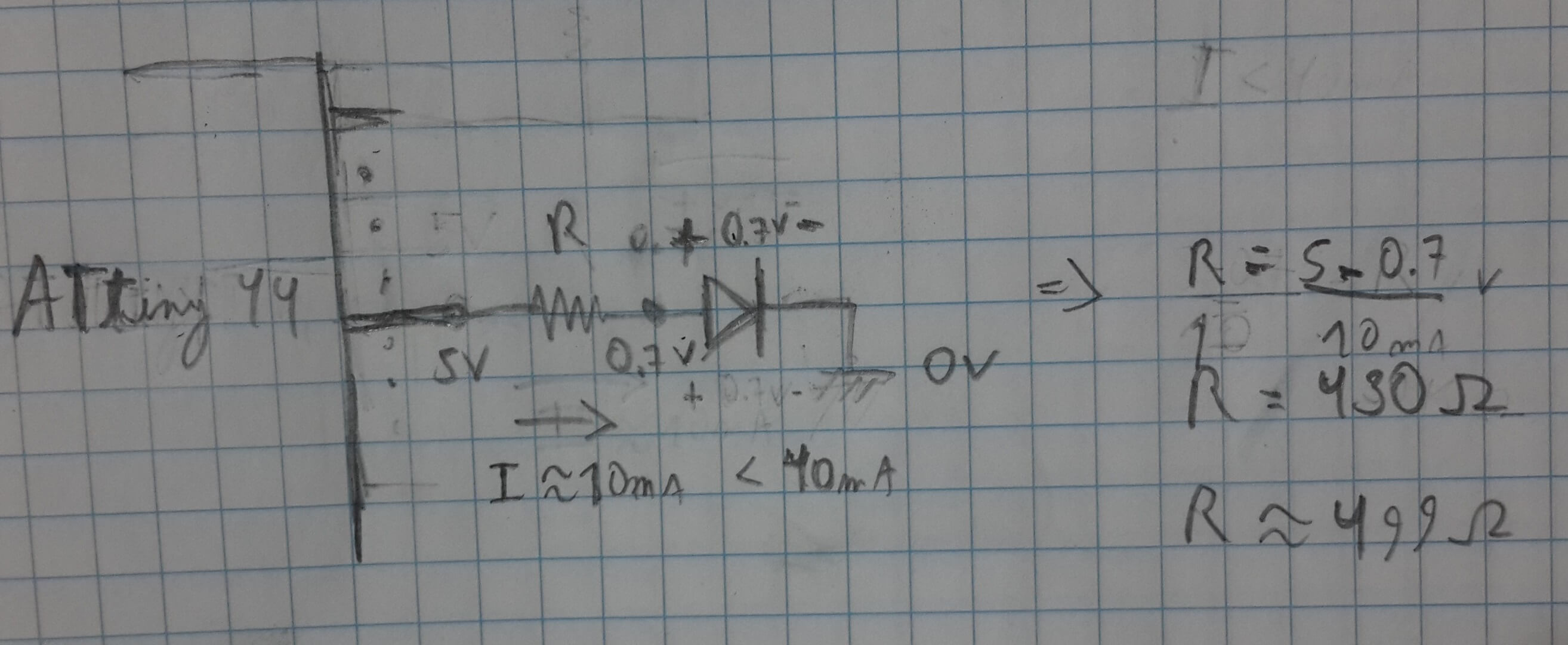
Solving this Ecuation for a 10 mA current I got:
10 = 4.3/R => R = 430 Ohm
But beacuse I did not have a 430 Ohm resistor, I chose a 499 Ohm resistor. Choosing this resistor value reduced the current a little bit
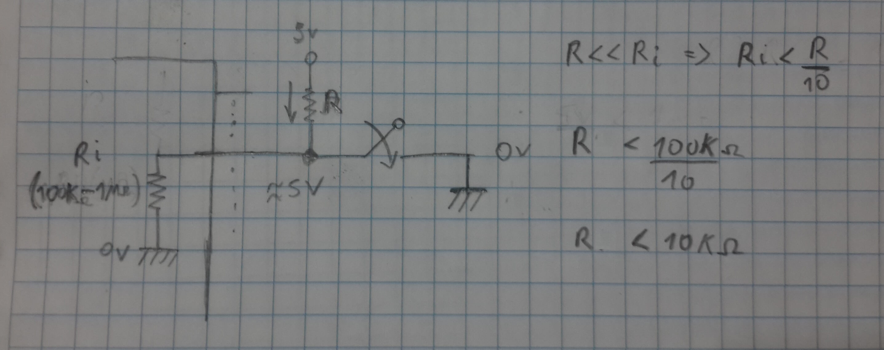
The other component i needed to add was a switch. When switching we must ensure that the output of it is 0v or 5v, and thus the output of the switch should be 5v or GND. I decided to use a pull up resistor with the switch, this would make the switch work with an inverted logic (0v when pusshed 5v when not pushed)
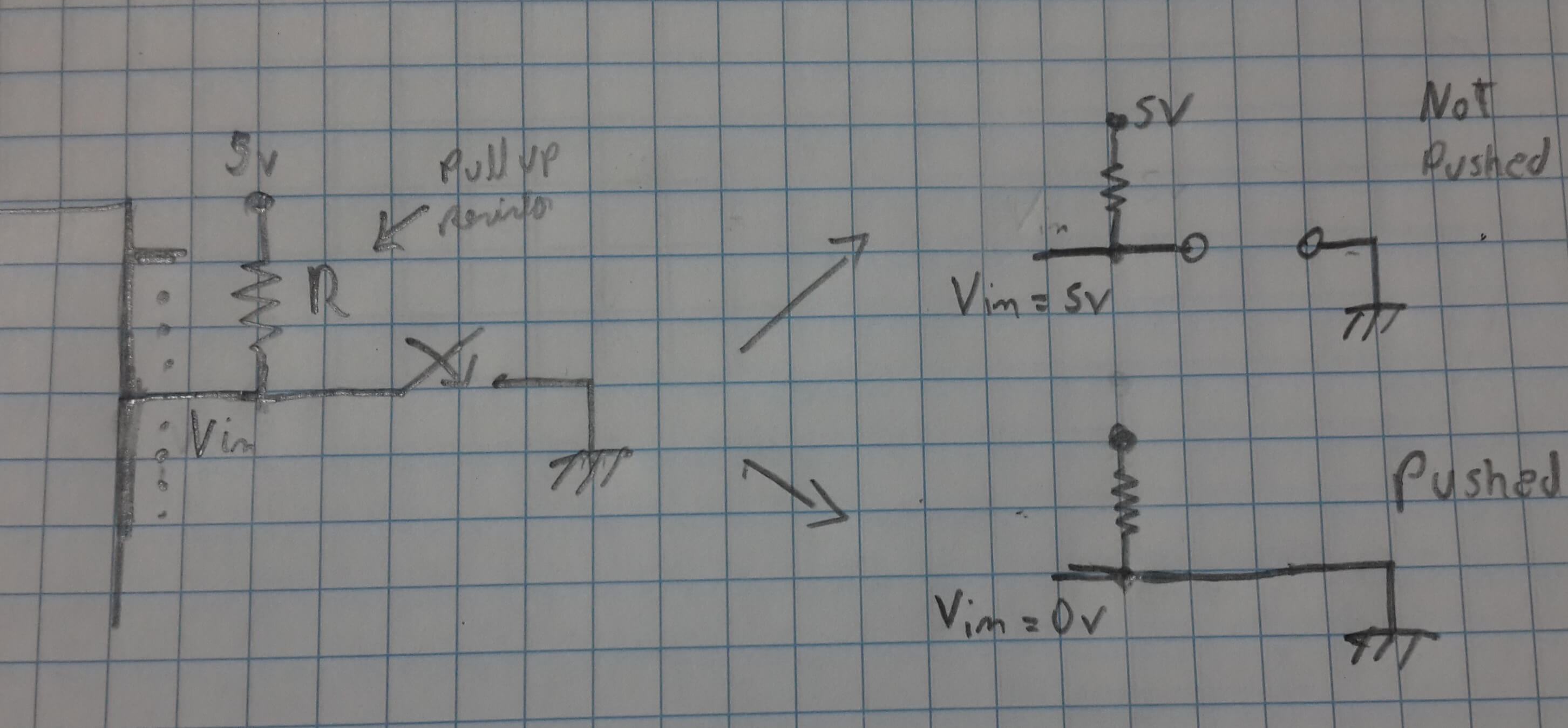
I needed to ensure that the current through the resistor was not too high when the button was pushed, since this would have caused that the circuit will consumed a lot of energy. Thus i needed to choose a high impedance resistor (for making the current smaller), but this resistor should not be too high so that it creates a voltage divider with the internal chip resistor. Generally, the internal resistors are in the order of 100 kOhms to 1 MOhm or above so, i chose a resistor which was at least much more lower than 100; I chose 100 KiloOhms.
Working With Eagle
In general this are the steps i did:
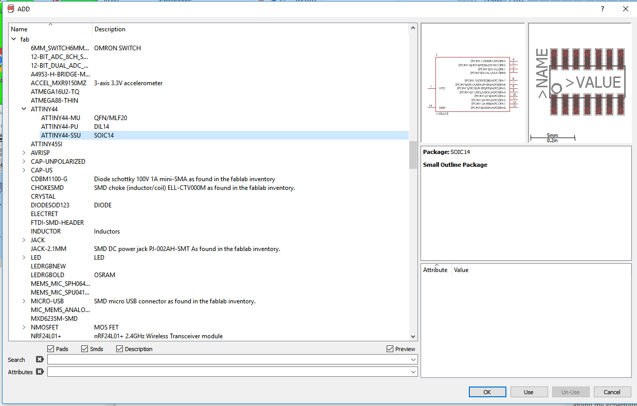
1. First, I downloaded the fab library for using the components that do not appear on Eagle, like the Attiny 44.
2. Then, I putted the library into the lbr folder which is inside my Eagle instalation folder. Im my case the lbr folder location is at:
C:\EAGLE 8.0.2\lbr
4. Then, i just started to drag, to the schematic, all the necessary componnets for making my circuit by using the add tool, located at the left side toolbar.
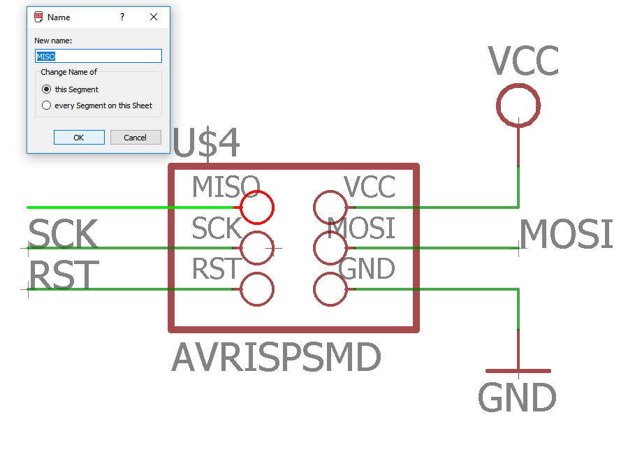
5. By using the net tool I joinned all the components of my circuit. F
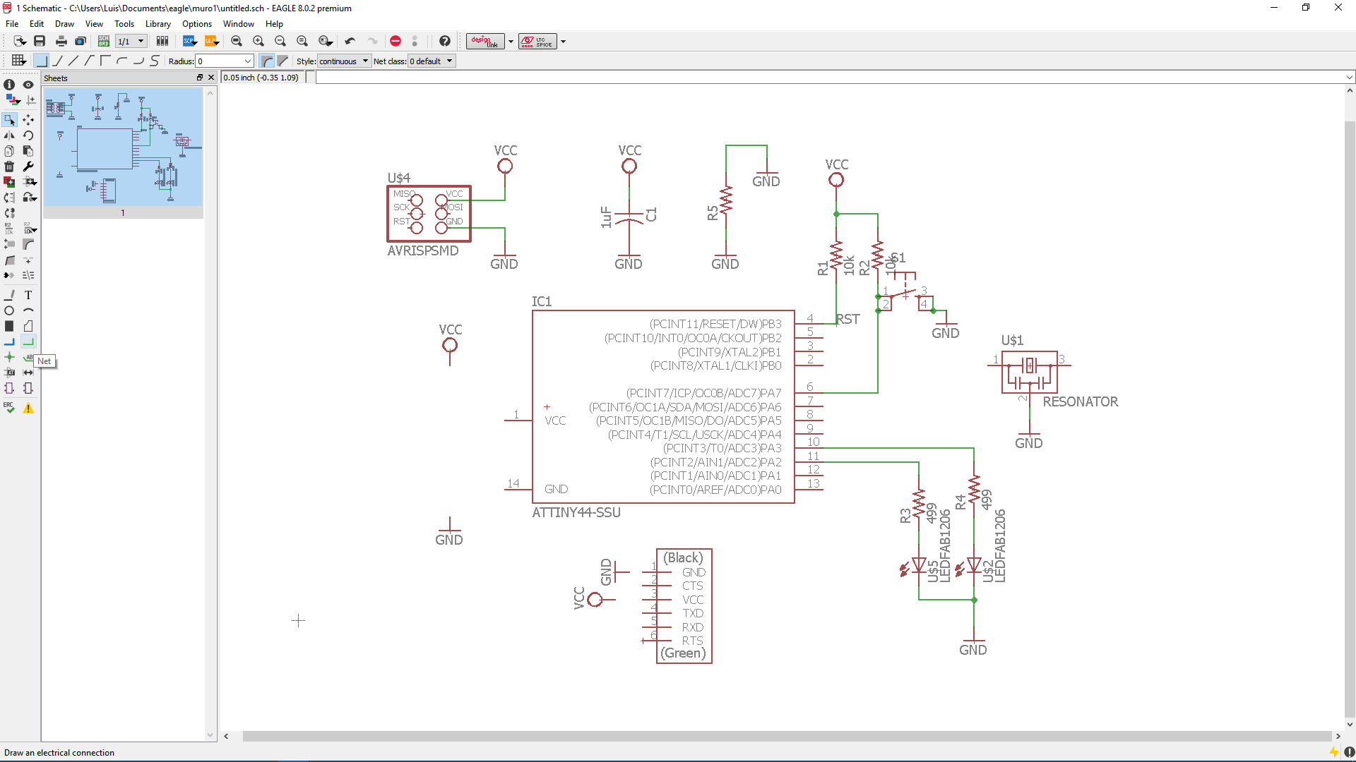
For making it in an ordered way, I used the name tool for namig the wires connections and the label tool for showing them on the schematic.
6. Once I finished doing my schematic, I jumped to the board window (this is done by pressing "switch to board" on the file menu option).
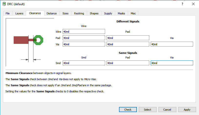
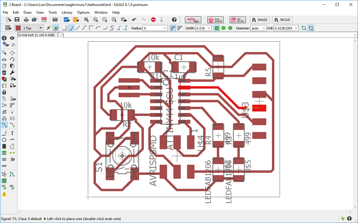
7. Since the end mill that was going to be used for milling the board had a diameter of 1/64 inches (around 0.156 inches or 0.39 mm), the minimum distance between signals that the board could be milled was of 1/64''. So, I clicked on DRC (Design Rules) and defined the minimum distance between all the pads, vias and wires as 40 milimeters, a little bit bigger than the diameter of the end mill.
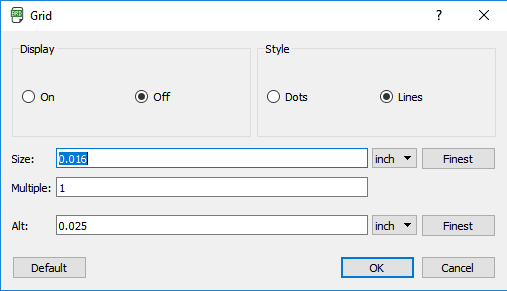
8. I clicked on grid and defined it as 0.016 inches which is a little bit biger than the diameter of the end mill (0.156 inches).
And then I started to route the circuit by using the route tool.
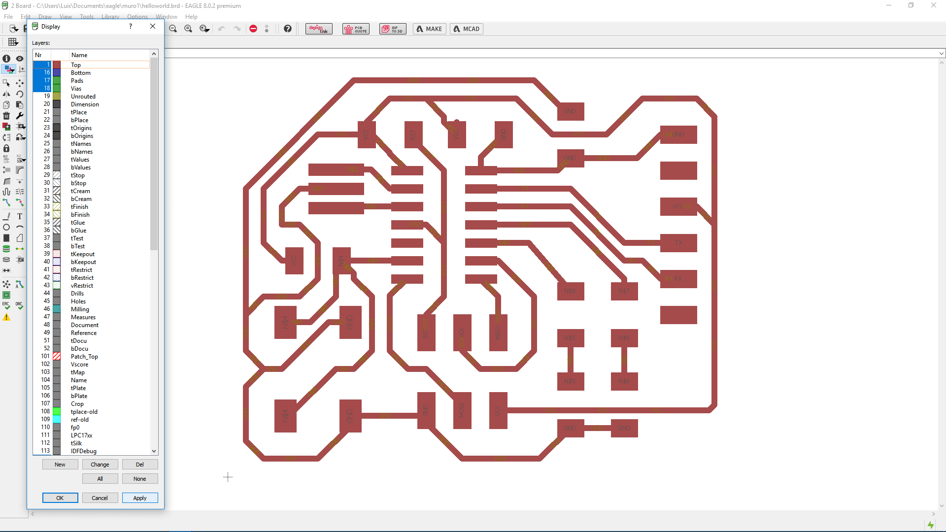
8. When I finished the board, I clicked on the layer settings button and deselected all the options except top, botton, pad and vias.
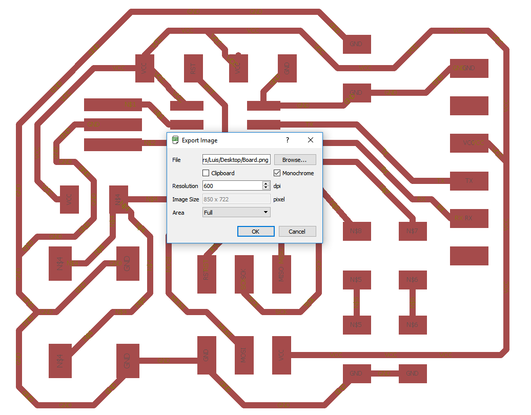
9. Then I exported the circuit as an image, by clicking on file->export and then choosing the monochrome option and setting the density inmage to 600 dpi.
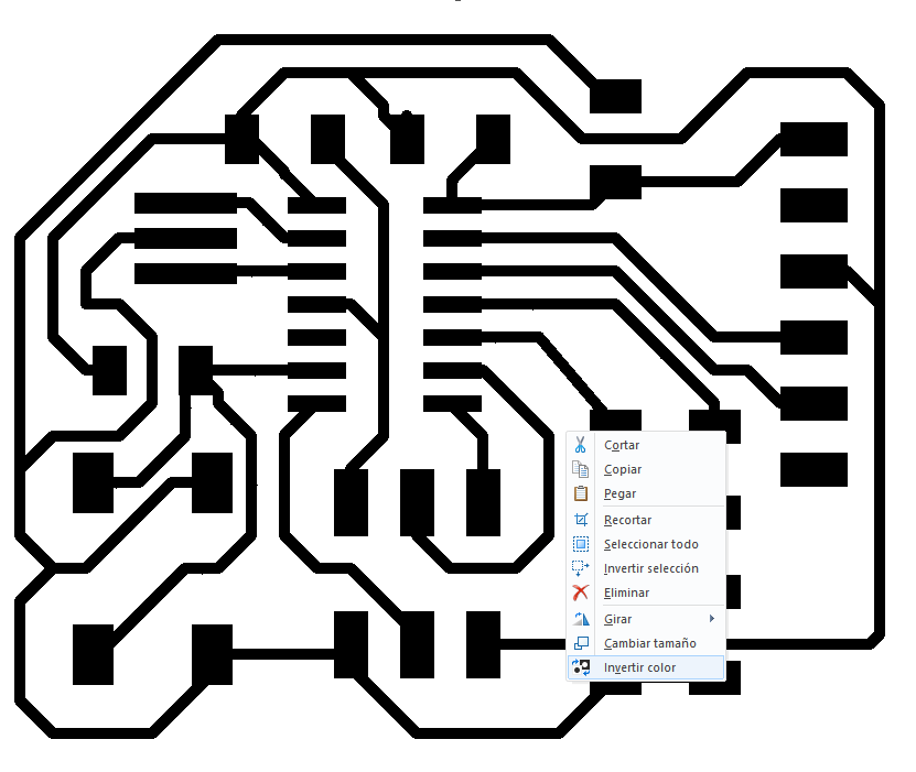
10. The resulting image is the negative of the image i want. So I oppened the image on Paint and inverted it the color.
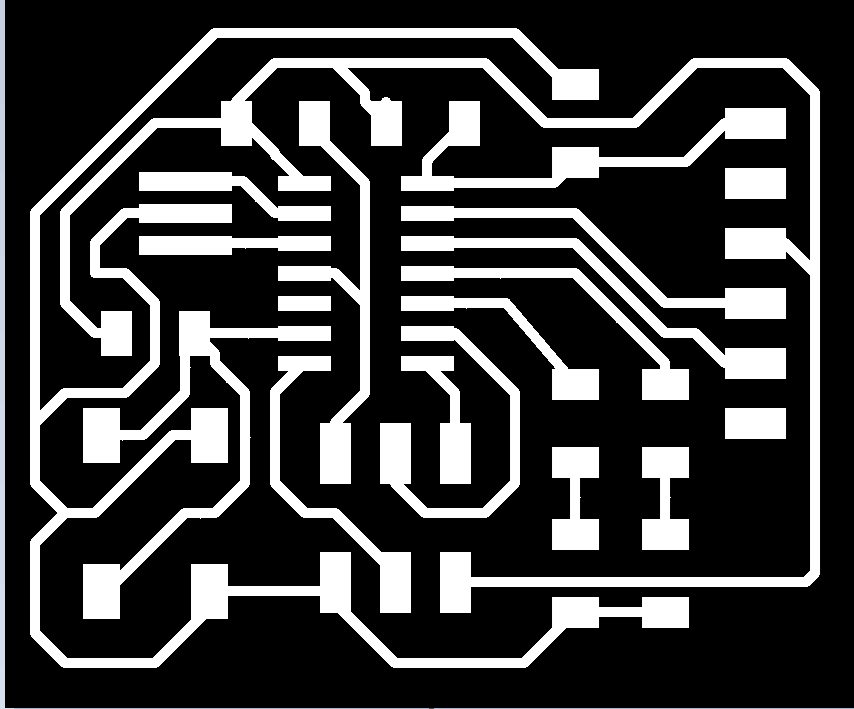
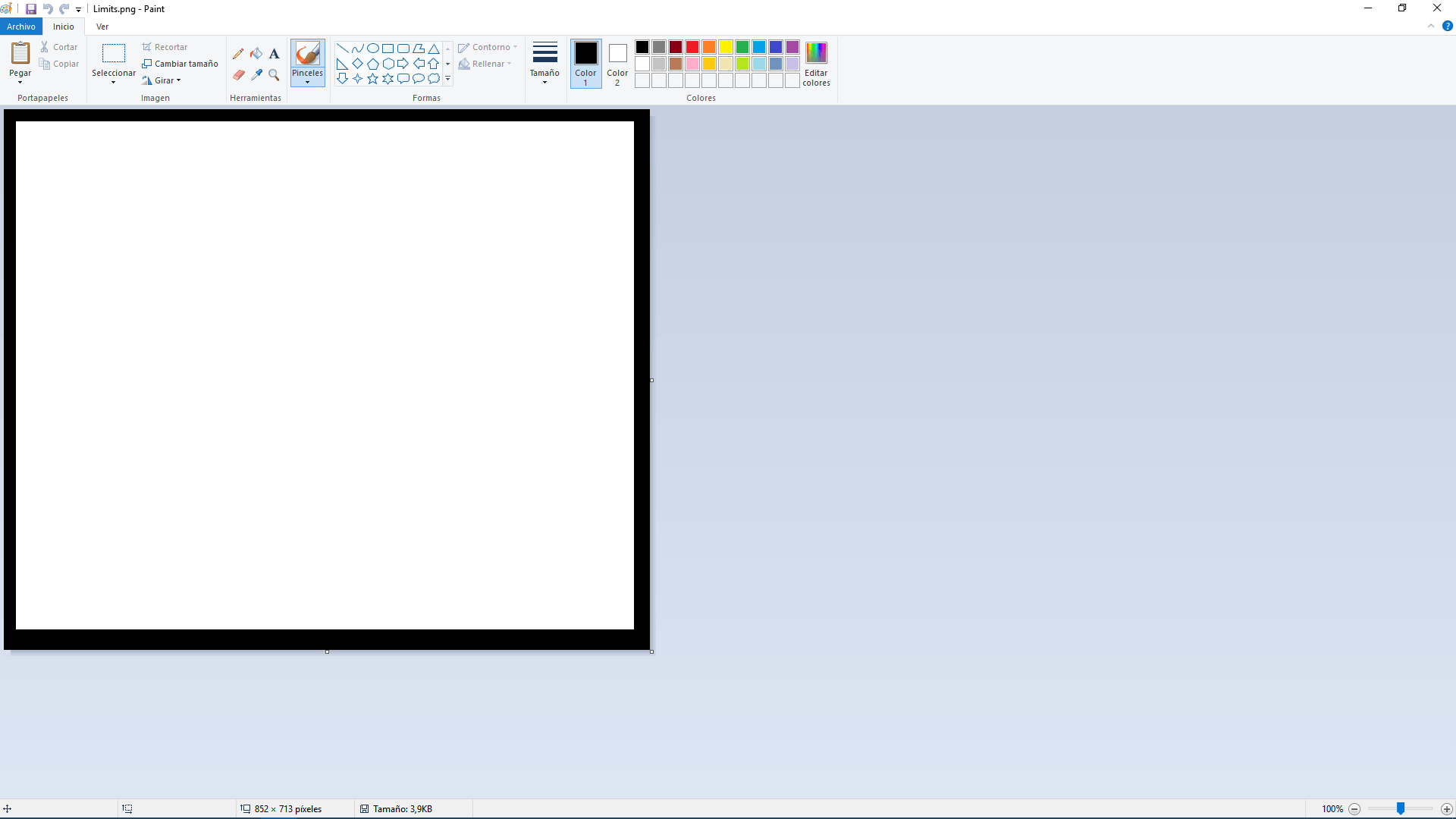
11. Since i had problems exporting the dimensions of the circuit, i created a copy of the image and edit it by erasing all its content and drawing the circuit limits.
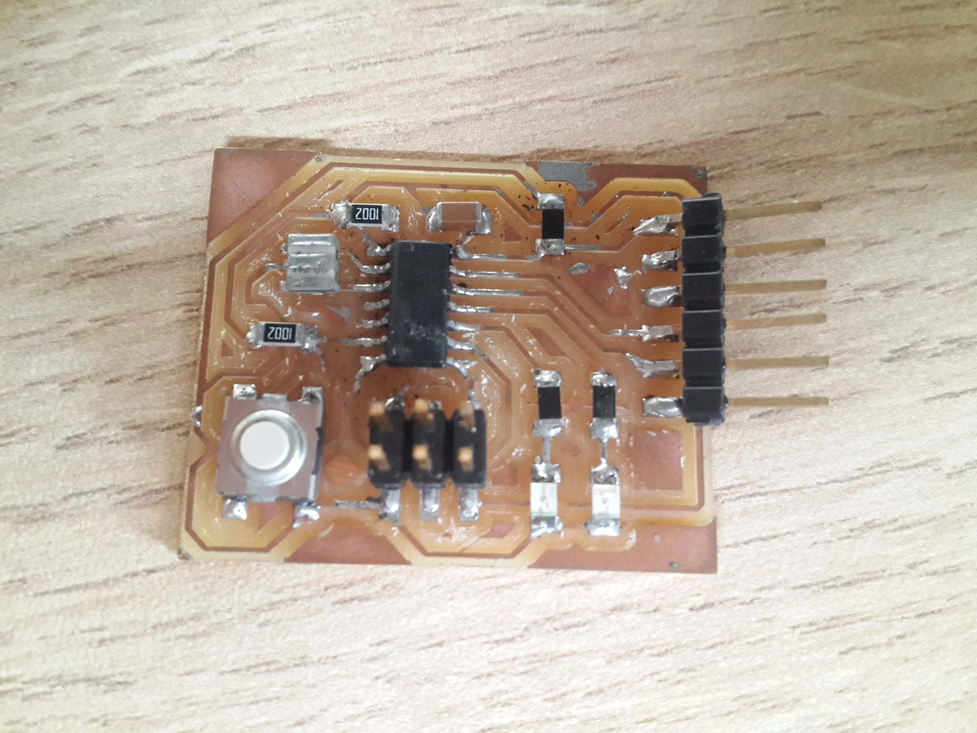
Making the circuit
I used the milling machine Modela MDX-20 for making my circuit, All the necesary steps for working with this machine are explained here
.
Programming the Circuit
I had to make sure that the designed circuit worked well, so i had to upload a program into the microcontroller for testing my circuit.
Firstly, I burned a bootloader to the mircrocontroler Eprom by using the programmer I made on the 4th week assignment. This is a program that permits to upload programs into the flash memmory of the microcontroller. For developing this task i followed this tutorial
This are the steps I followed to upload the bootloader:
1. I added the following url to the "Additional Boards Manager URLs" field on the Arduino preferences, so that it appeared like on the board manager for its download and instalation.
https://raw.githubusercontent.com/damellis/attiny/ide-1.6.x-boards-manager/package_damellis_attiny_index.json
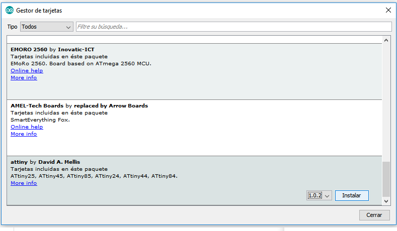
3. Then, I chose my board as ATtiny on the Arduino IDE by selecting ATtiny on Tools>Board, chose the programmer as USBTinyISP on Tools>Programmer and selected the clock frequency as 20MHz
4. After that, I used the programmer I made on the 4th assigment to burn the bootloader program in the Attiny. For this, i conected the Programmer to the pc with a usb cable and connected the programmer with the circuit by their ISP ports.
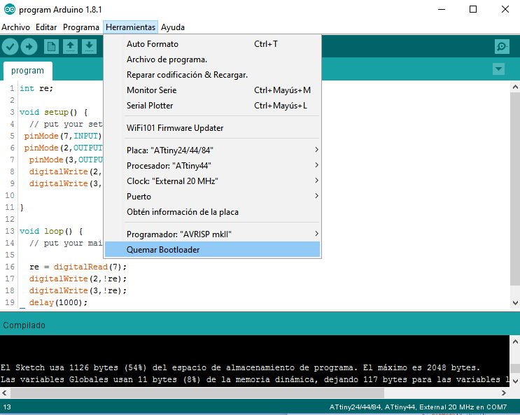
5. Finally, I selected the option Burn Bootloader on the tools menu of the Arduino IDE and waited untill it finished. This only setted the fuses for using the external 20 MHz clock. And thus every time the board needs to be loaded with some program, it requires the use of an ISP programmer.
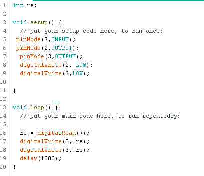
Then, I created a little program on the Arduino IDE, which consists on turnining on the leds when the pulsator button is pushed
The first part of the code, consisted on defining the output and input pins with the function pinMode. And since this needed to be done only once, it was defined on the setup function. For this case the button was connected to pin 7 and the leds to pins 2 and 3.
The second part of the code consisted on turning on and off those leds, indefinitely, with the function digitalWrite. And since this needed to be done indefinitely, it was defined in the loop function.
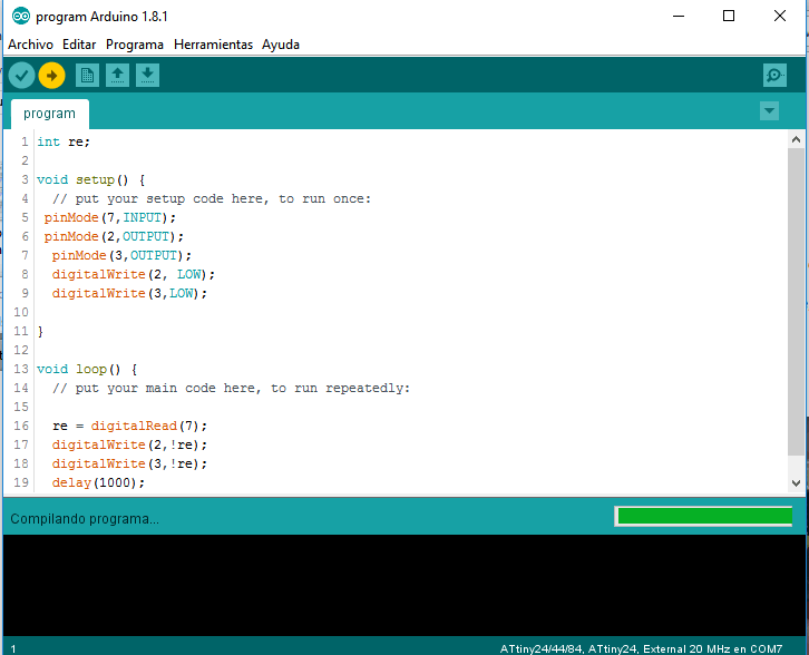
After that, I uploaded the program to the microcontoller. By doing the next steps:
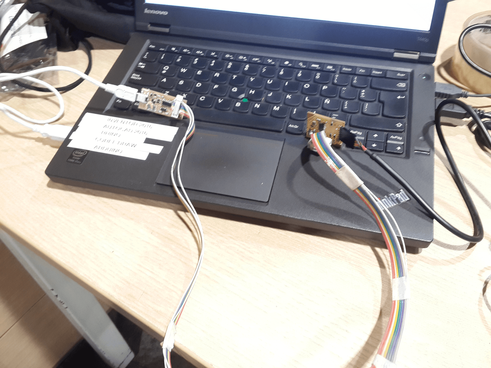
1. I supplied voltage to the board with the FTDI cable, and, optionally, I installed the FTDI drivers.
2. I checked that the configuration was as follows:
- Board:: ATtiny24/44/84
- Procesor: ATtiny44
- Clock: External 20 MHz
- Programmer: USBtinyISP
3. Then clicked on upload and wait untill it finishes.
Finally I tested the circuit.
Simulating The Design
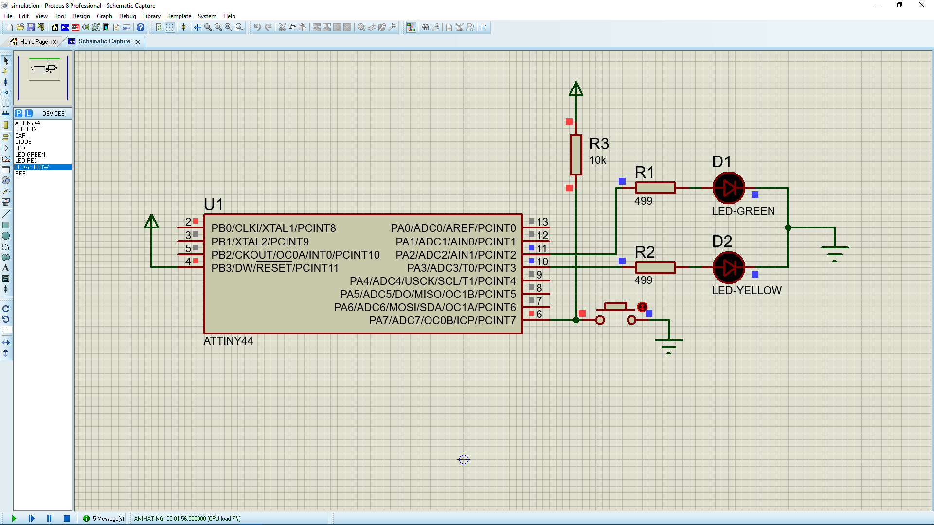
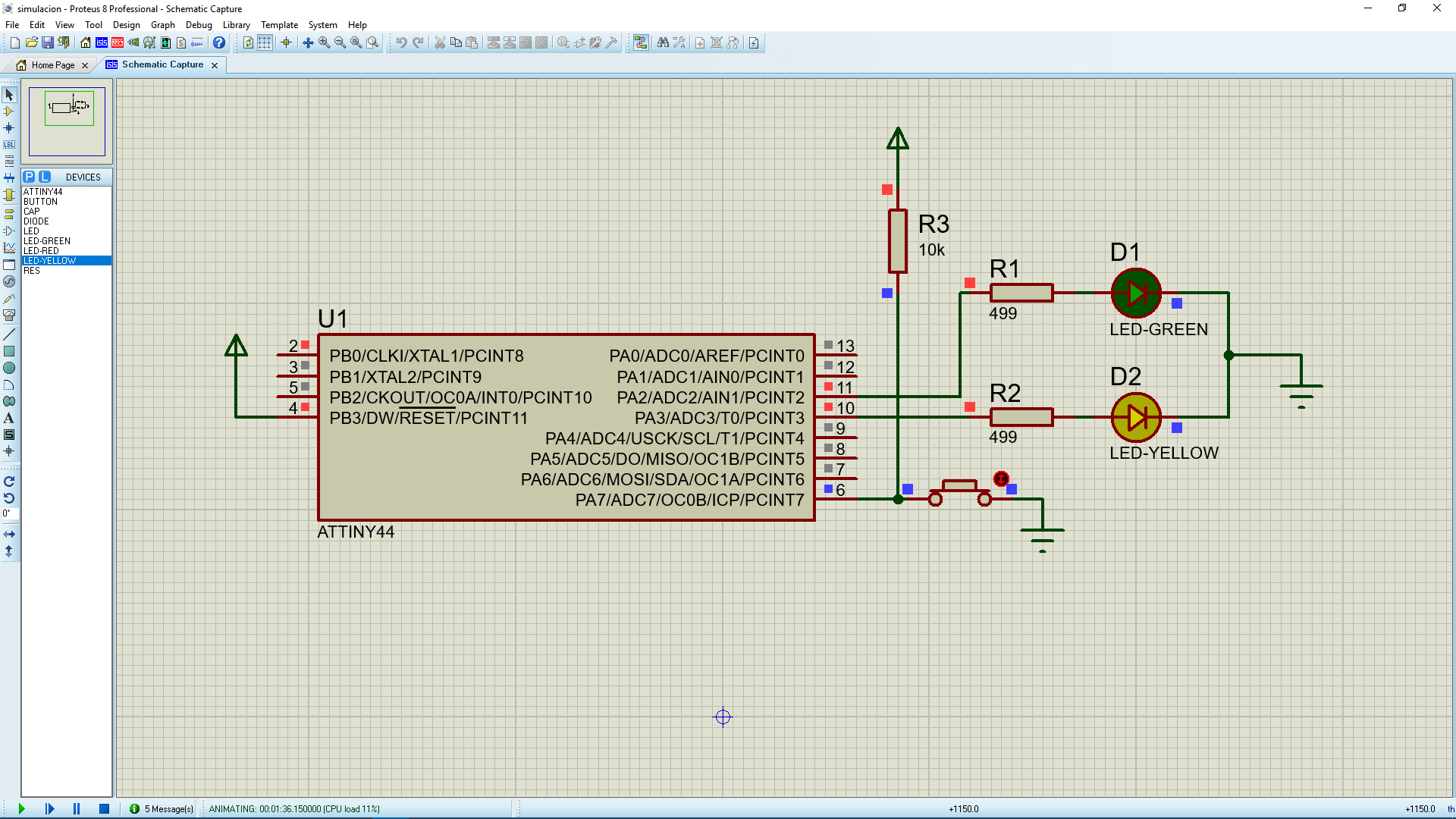
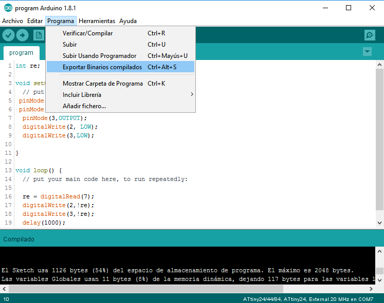
Additionally, I simulated the circuit logic on Proteus. For doing this, I exported the compiled Hex file of the program, by clicking on Program>Export Compiled Binary.
I did a short version of the shematic on proteus.
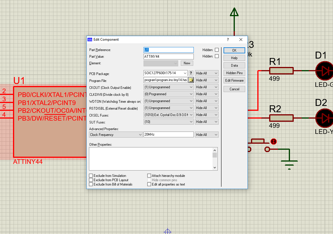
Then, I clicked on the Attiny properties and loaded the program Hex file and changed the oscilator frequency to 20 MHz
And finally, I ran the simulation: