Computer Controlled Cutting
For this assigment, we have to:
- (DONE) Make lasercutter test part(s), varying slot dimensions using parametric functions, testing your laser kerf and cutting settings (group project).
- (DONE) Cut something on the vinylcutter.
- (DONE) Design, make, and document a parametric press-fit construction kit, accounting for the lasercutter kerf, which can be assembled in multiple ways.
- (DONE) Make a sticker or a flexible circuit boards or a textured surface or a relief pattern or a screenprint resists/stencils.
All the files created for this assigment can be found on the link bellow:
---> DOWNLOAD FILES<---
a) Laser Cutting
Have you:
- Explained how you parametrically designed your files?
--> yes
- Shown how you made your press-fit kit?
--> yes
- Included your design files and photos of your finished project?
--> yes
b) Vynil Cutting
Have you:
- Explained how you drew your files?
--> yes
- Shown how you made your vinyl project?
--> yes
- Included your design files and photos of your finished project?
--> yes
Testing Parts
The first test we made consisted on finding the best settings for laser cutting for different kind materials and board thickness. For this test, we tested the materials by doing holes with different configuration settings.
The steps we followed for finding the best configuration for laser cutting were the next ones:
1. We looked for boards that were different in thickness and material (We chose an MDF board, an acrilic board, an aeromodelism wood board and leather).
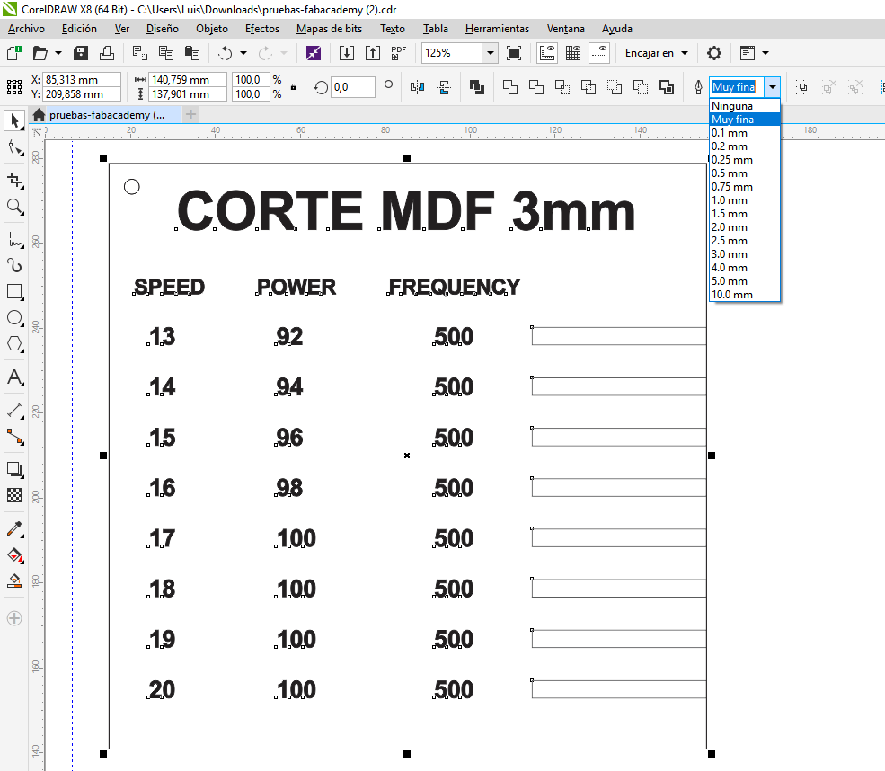
2. We sketched on Corel Draw a template for finding the best configuration for cuttting the board selected. This template consisted on a list of combinations of speed an power settings and a hole next to each combination,which should be done with the indicated settings.
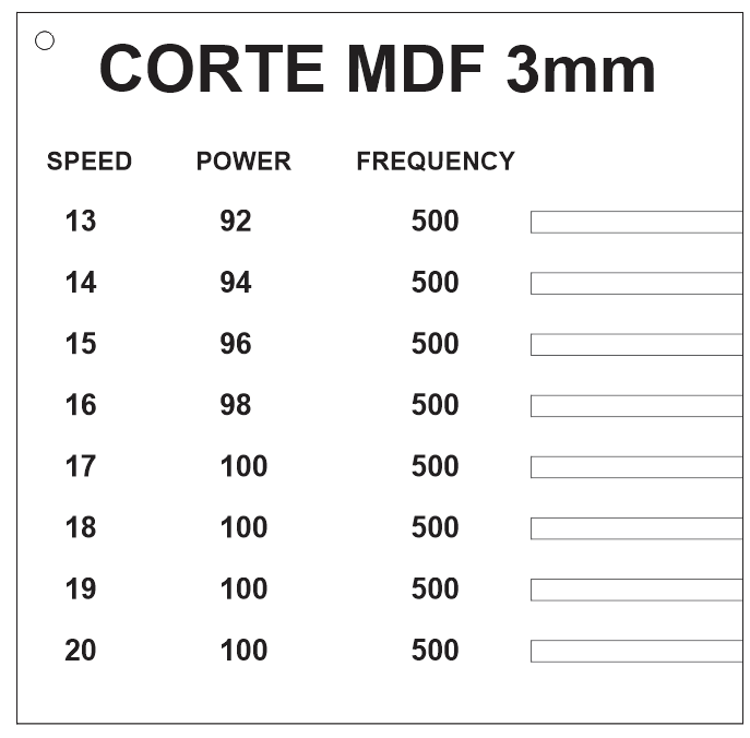
3. We selected all the holes and changed its width contour as "very fine".
4. We selected with the mouse one of the combination settings and hole pairs on the template.
5. We open the printing settings and chose "selection" as a print option.
6. We open the laser cutter printing settings and inserted the selected speed and power settings.
7. We checked on "autoFocus" and changed the document width and height to the size of the board (300x600).
8. We accepted the settings and sent it to print.
9. We repeated the steps from 5 to 9 for each configuration pair.
10. We looked on the template which holes were done without problems, and selected the one with the highest speed.
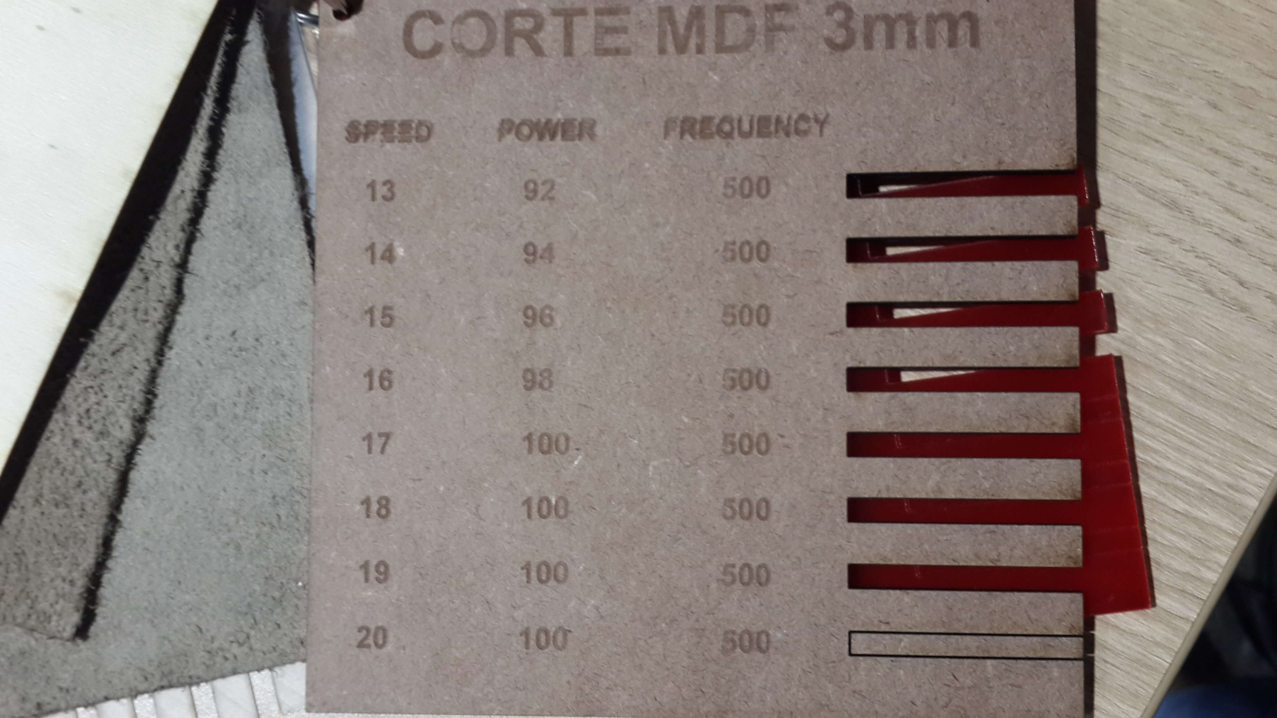
For MDF it was 100 of power and 17 of speed.
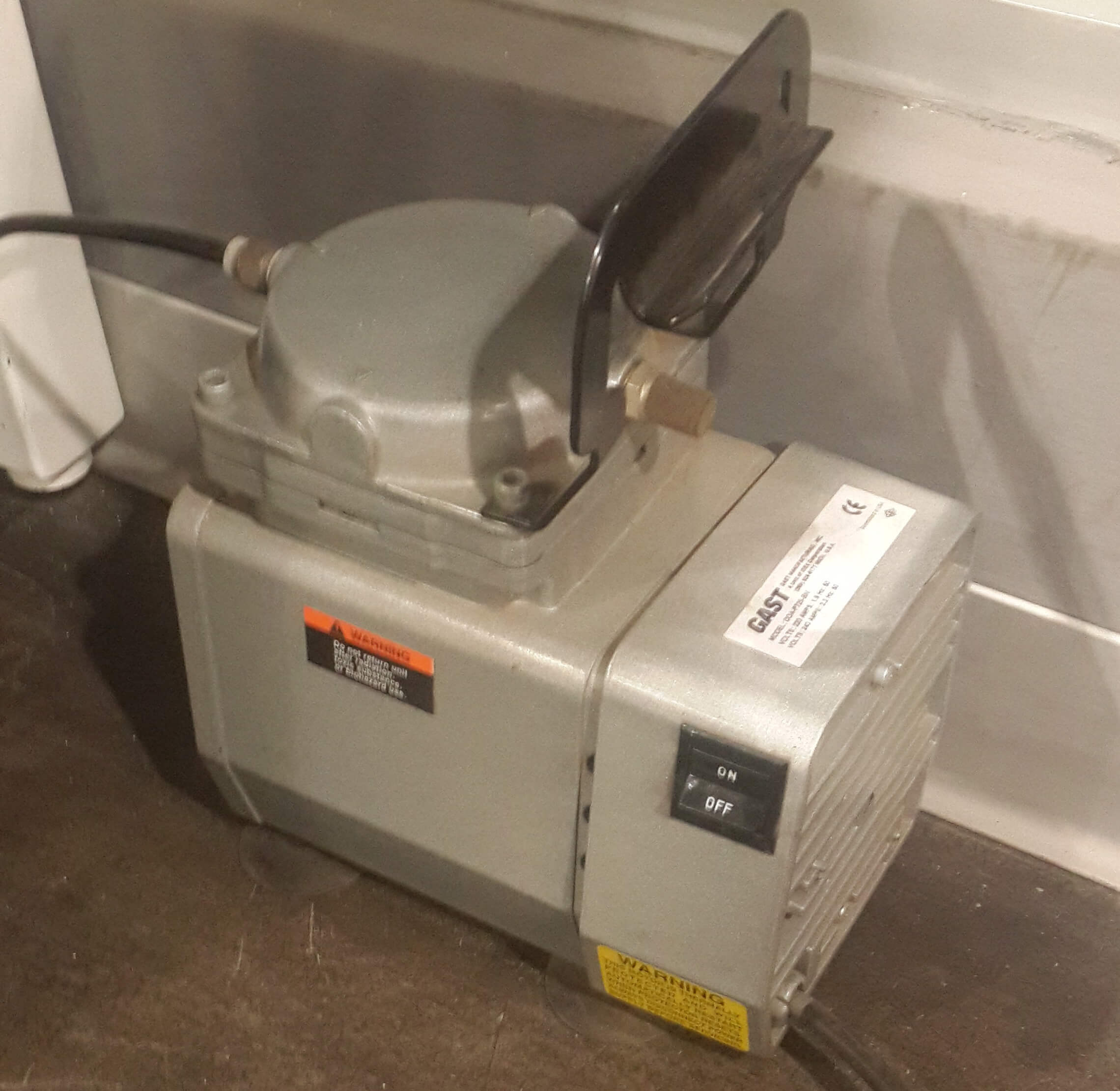
At the same time, we prepared the lasser cutter by doing the next steps.
1. We turned on the air compresor.
3. We putted the board inside the laser cutter on the top left corner.
4. We waited for the printing order comming from the pc and accepted it.
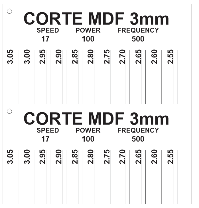
The second test we made, consisted on finding the best hole dimensions that a piece should have so that it perfectly fit into another. By doing this, we realize how much extra material does the laser removes from the board.
Basically we made the same steps done in the previous test, with the difference that this time, the template consisted on a set of holes of different sizes. The steps followed were the next ones:
1. We looked for boards that were different in thikness and material (We chose an MDF board, an acrilic board, an aeromodelism wood board and leather).
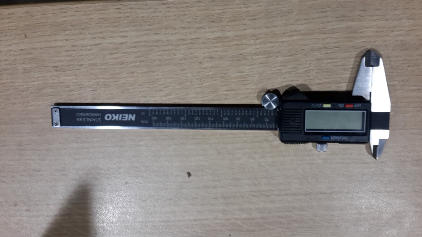
2. We meassured the thicknesss of the material by using a electronic vernier.
4. We selected all the holes and changed its width contour as "very fine".
5. We selected with the mouse one of the combination settings and hole pairs on the template.
6. We open the printing settings and chose "document" as a print option.
7. We open the laser cutter printing settings and inserted the best configuration settings found on the first test.
8. We checked on "autoFocus" and changed the document width and height to the size of the board.
9. We accepted the settings and sent it to print.
10. We printed a copy of this template.
11. We tested which size hole was the best by fitting one printed piece into the other for each hole.
12. We selected the one that did not make the pieces slide. For MDF the best size of hole was 2.9 mm.
Cutting On The Vinyl Cutter
The first things i did was to create an image on inkscape. The image consisted on a skull
and was based on tu torialwich can be found here.
1. Create a circle for the head.
2. Create an elipse for the pommels and overlap it to the first circle.
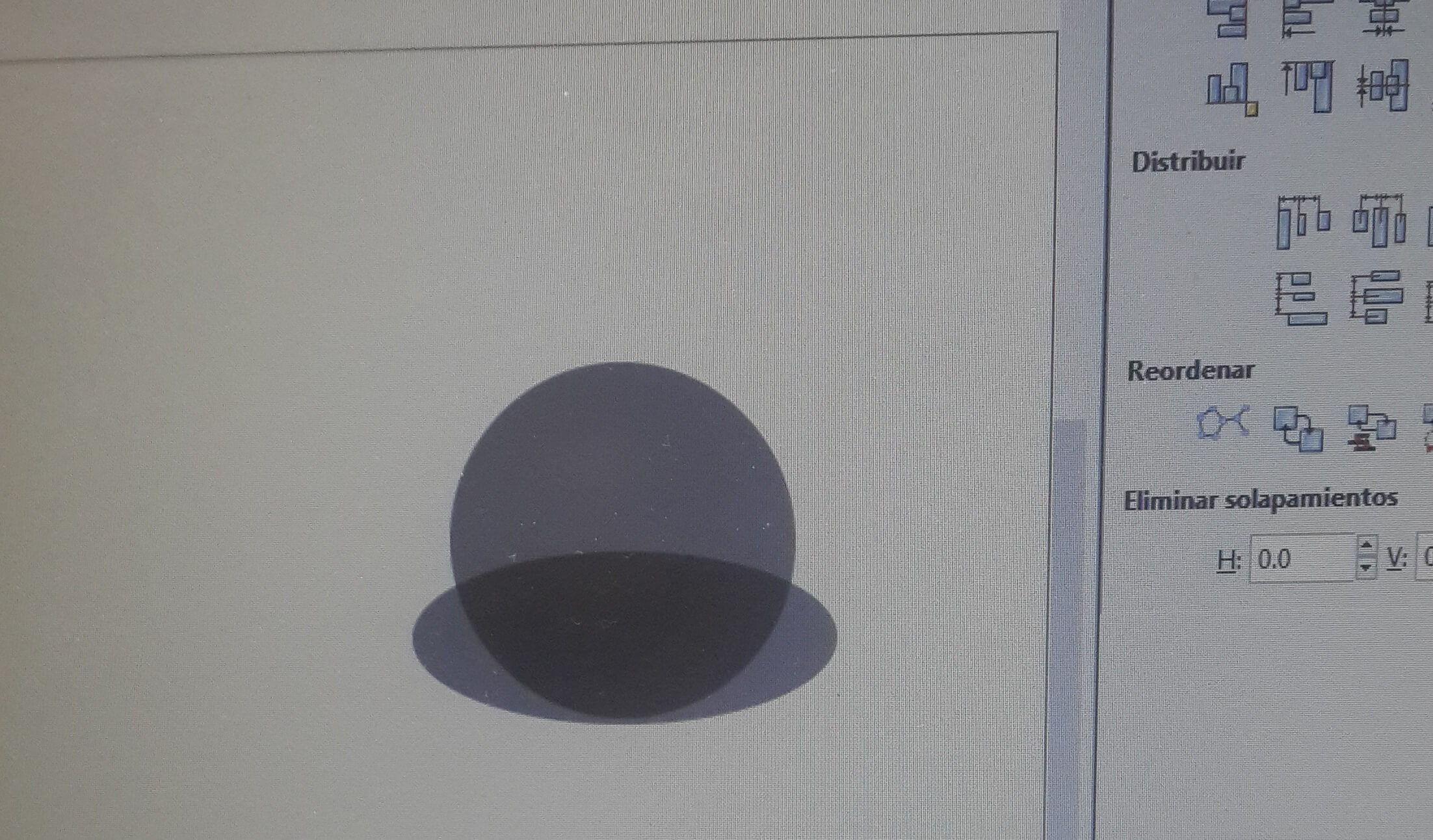
3. Combine both figures.
4. Create a couple of circles for the eyes and a triangle for the nose and put it on the combined figure.
5. Edit the nodes of the circles and the triangle as you want.
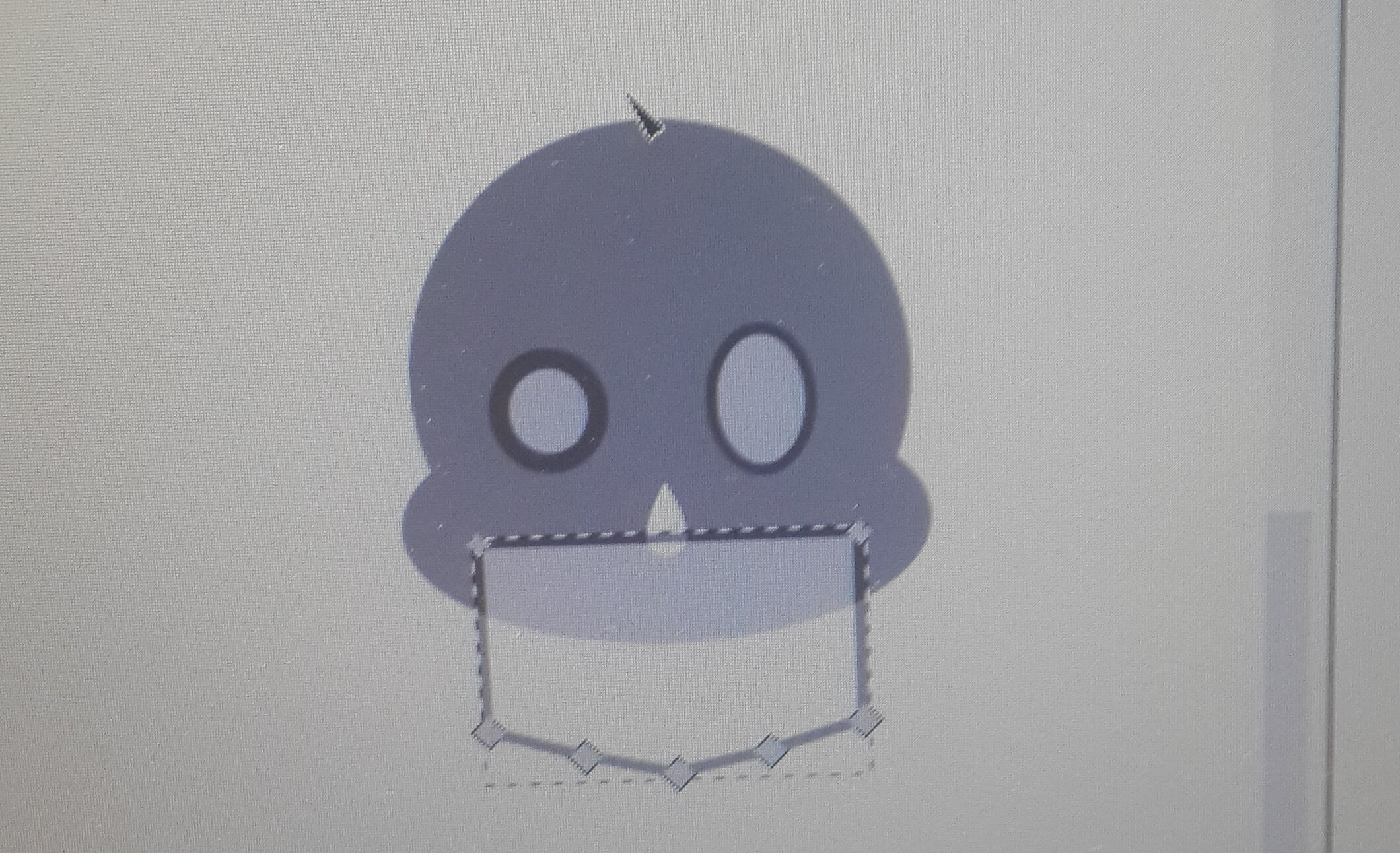
6. Create a rectangle for the jaw and put it over the combined figure.
7. Align the rectangle and the cobined figure with the align tools.
8. Add nodes to the base of the rectangle and modify it to give it the form of a jaw.
10. Create a shape similar to a imverted triangle for giving form to the backside of the jaw and modify its nodes.
11. Mirror the modified image.
12 Put both shapes over the combined figure (almost at the outer side of left and right side)
13. Differentiate the images from the combined image.
14. Differentiate the eyes and nose from the combined image.
15. Create a small rectangle for a teeth and copy and paste the until you get five of them.
16. Modify the nodes of the rectangle so that it ends rounded.
17. Distribute them over the combined figure and then substract them.
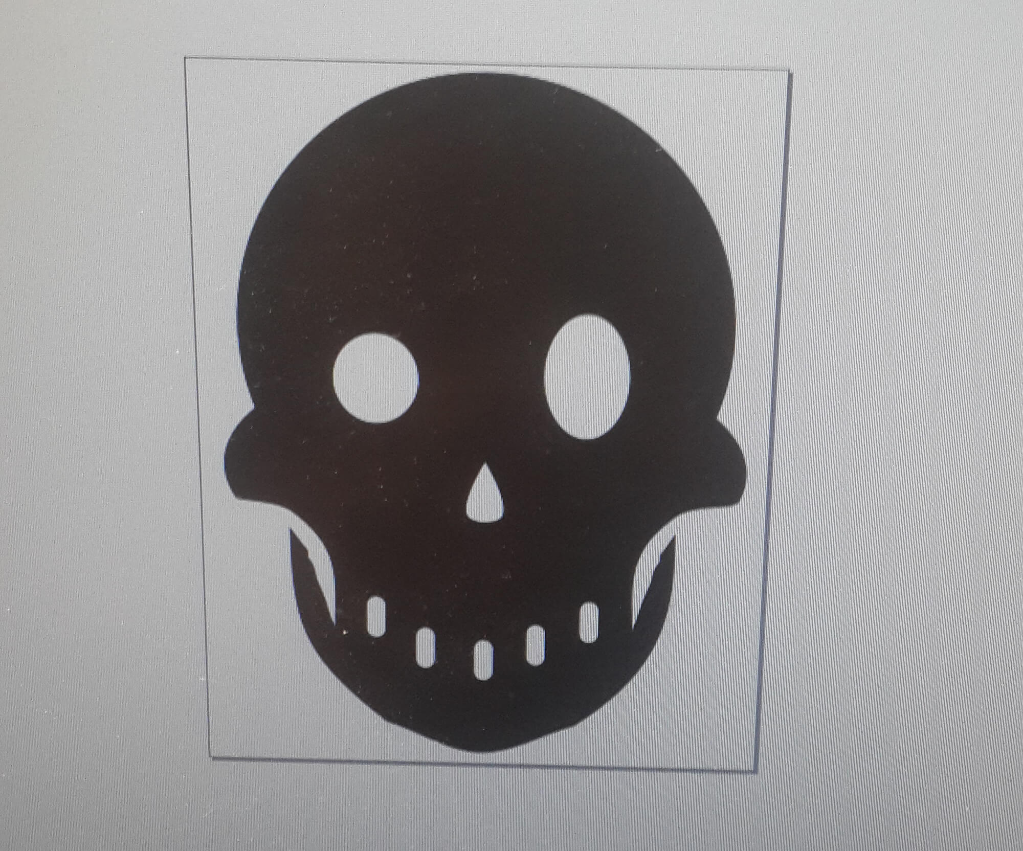
18. Modify the nodes of the resulting figure.
19. Save the image with the .png extension.
The resulting image can be found here. Then, for cutting on the vinyl cutter i did the next steps:
1. Fit the document size to the size of the image.
3. Move the reels of the vinyl cutter to the place of the roll were you want to make the cuts.
4. Turn on the vinyl cutter.
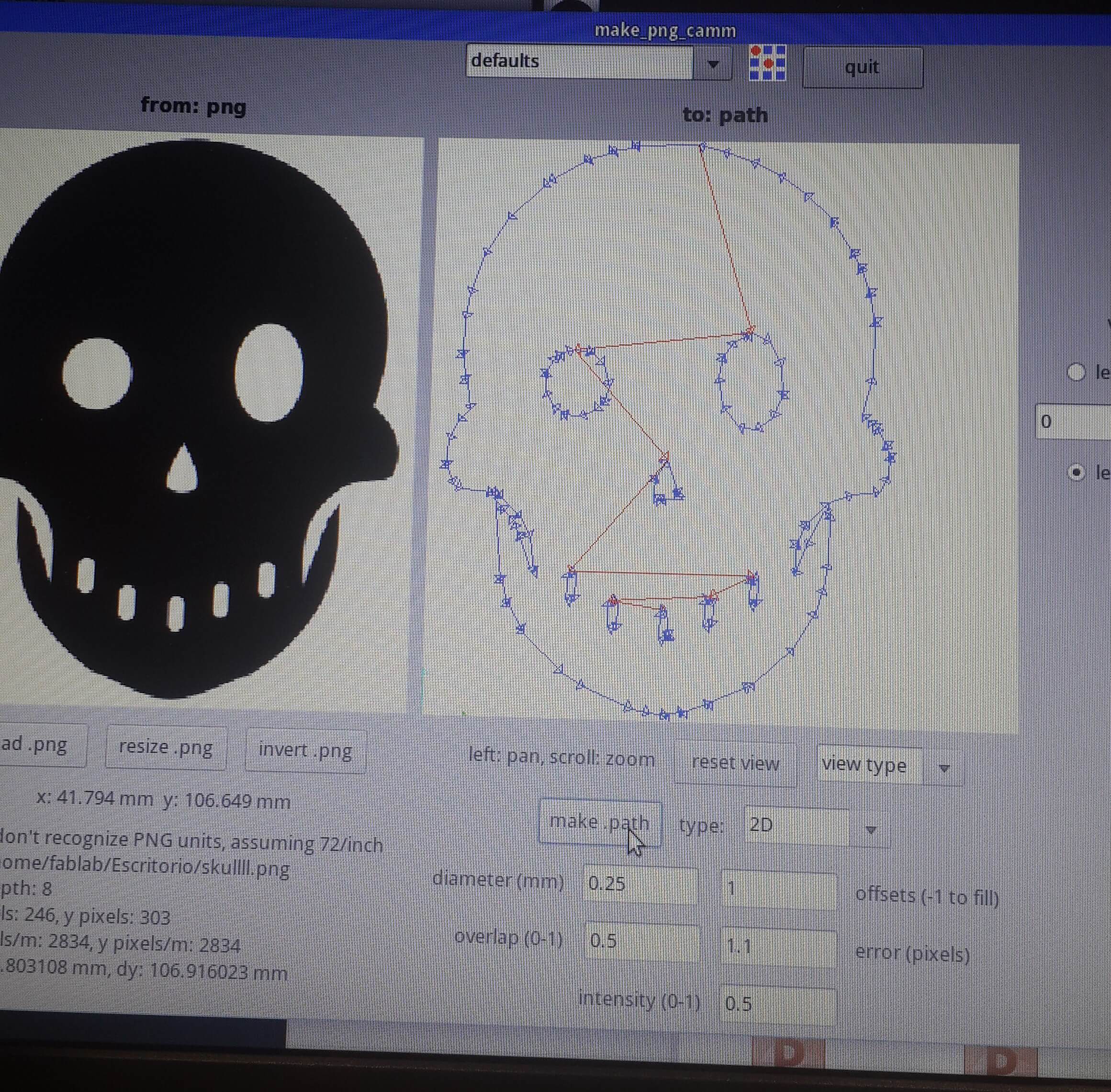
5. Open the fab module on a pc by typing sudo fab on a linux terminal and insert the requested password. 6. Select the input format as .png and select the machine to use and press make.
7. Load the image and fill the cutting settings(For the force, I chose 120 and for velocity, 5) and choose the type of material (vynil).
8. Press path to get the path that tha vinyl cutter is goint to follow and then press make_path.
10. Finally extract the residual parts from the vinyl and put a transfer foil over the vynil.
11. The resulting piece its an sticker. So pull out the transfer just when you are going to stick the sticker.
Making a Pressfit Kit 1
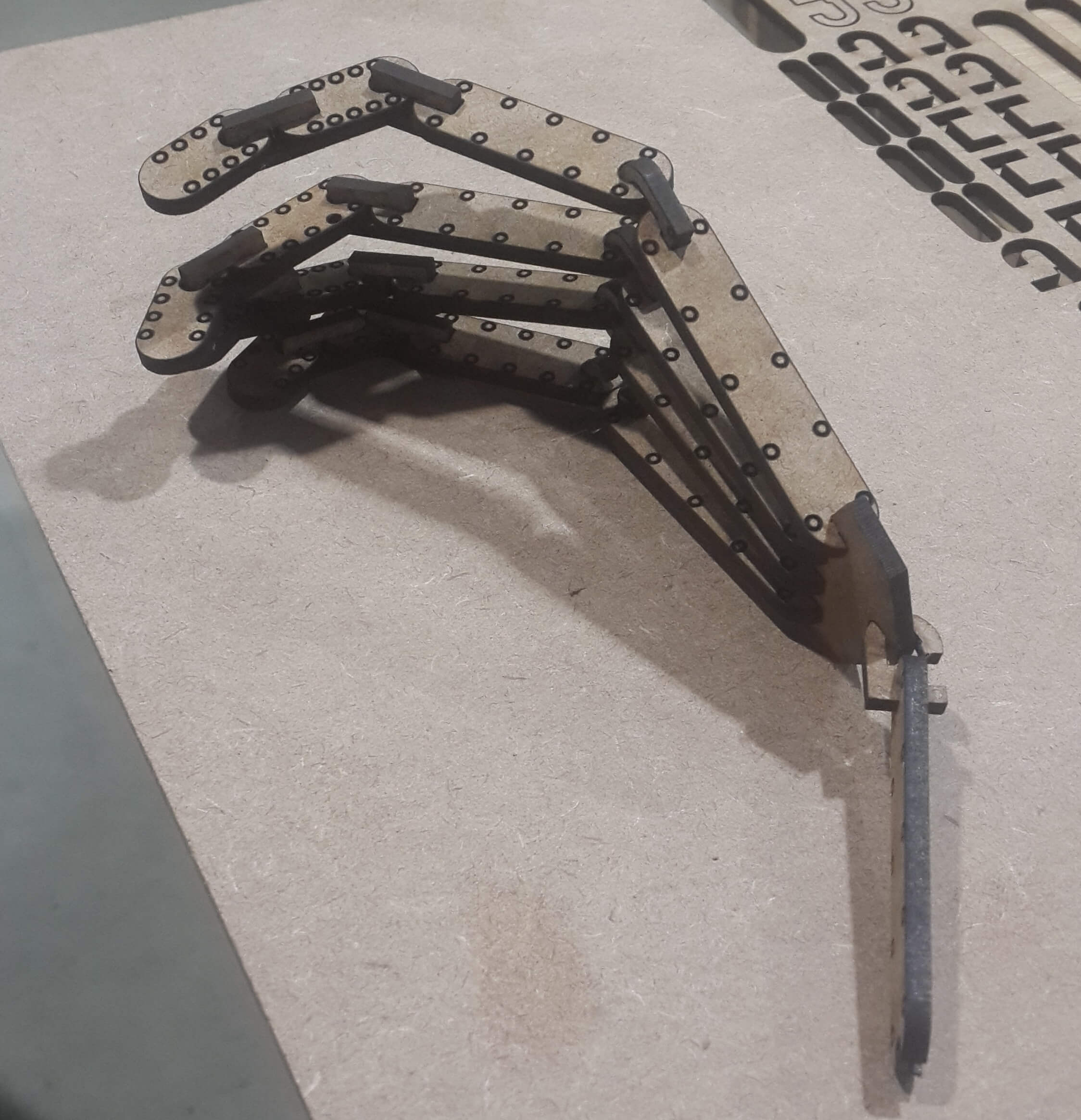
Having in mind that my final project consists on developing a robotic hand. I took this assigment for building a rapid prorotype of a multi DOF hand.
Firstly, i made some sketches on how this hand could have been built with a presfit kit, based on some previous sketches made for the first assignment. Basically, this was done just to test some ideas on how to generate movement on the fingers independently.
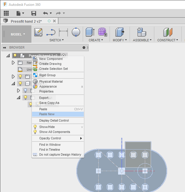
For building these pieces parametrically Iused Fusion 360, this software lets me check the final result with all the pieces joint virtuallly. I did the following steps:
1. On Fusion 360, I created a new component for making one of the pieces.
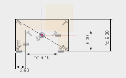
2. Inside the new component, I sketched a phalanx.
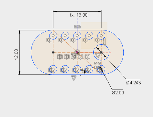
And then i made some modification to the copied phalanx.
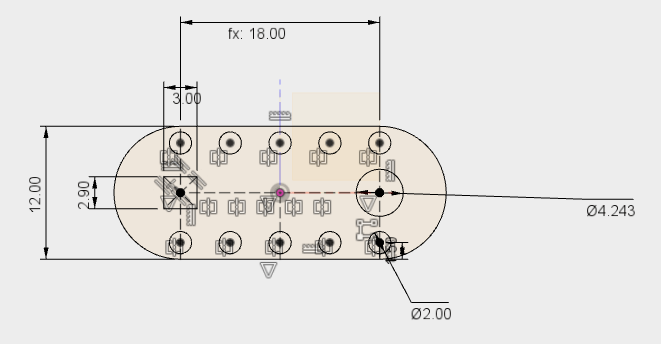
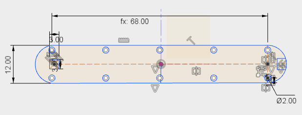
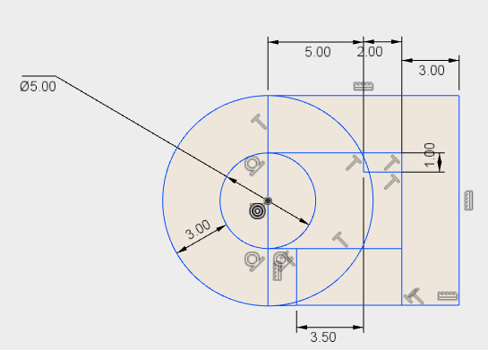
6. Then, I created piece for the carpios.
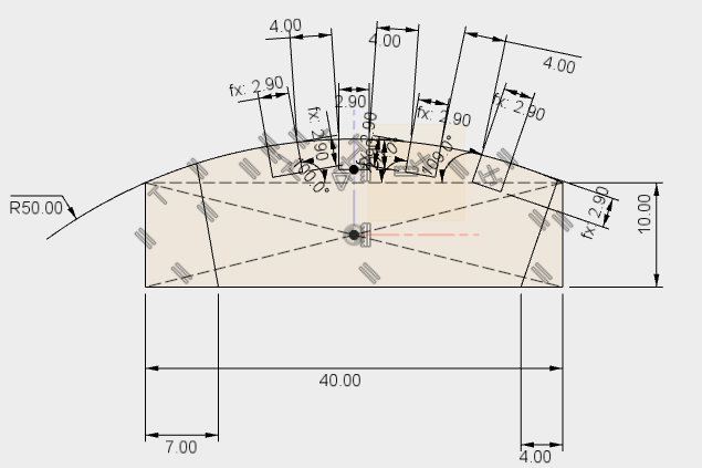
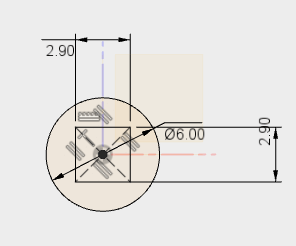
9. And finally, i modified all the size acording to my own hand size.
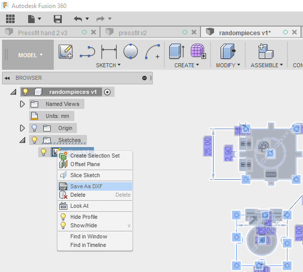
Once I finished making the pieces on Fusion 360, i exported them as a DXF file by clicking right on each sketch component and choosing the option "export as DXF file" and load each piece to Corel Draw. Once all the pieces were loaded i saved the corel draw file, which can be downloaded here .
For printing on the lasser cutter, I followed the esteps mentioned on the first section of this page.
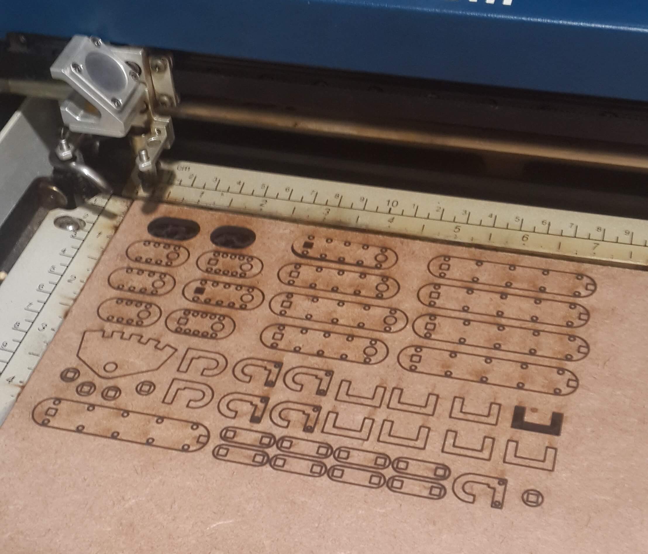
Having in mind the kerf, I printed only three pieces to check if they fit perfectly and then, once I verfied the measures were correct, I printed the rest of the pieces.
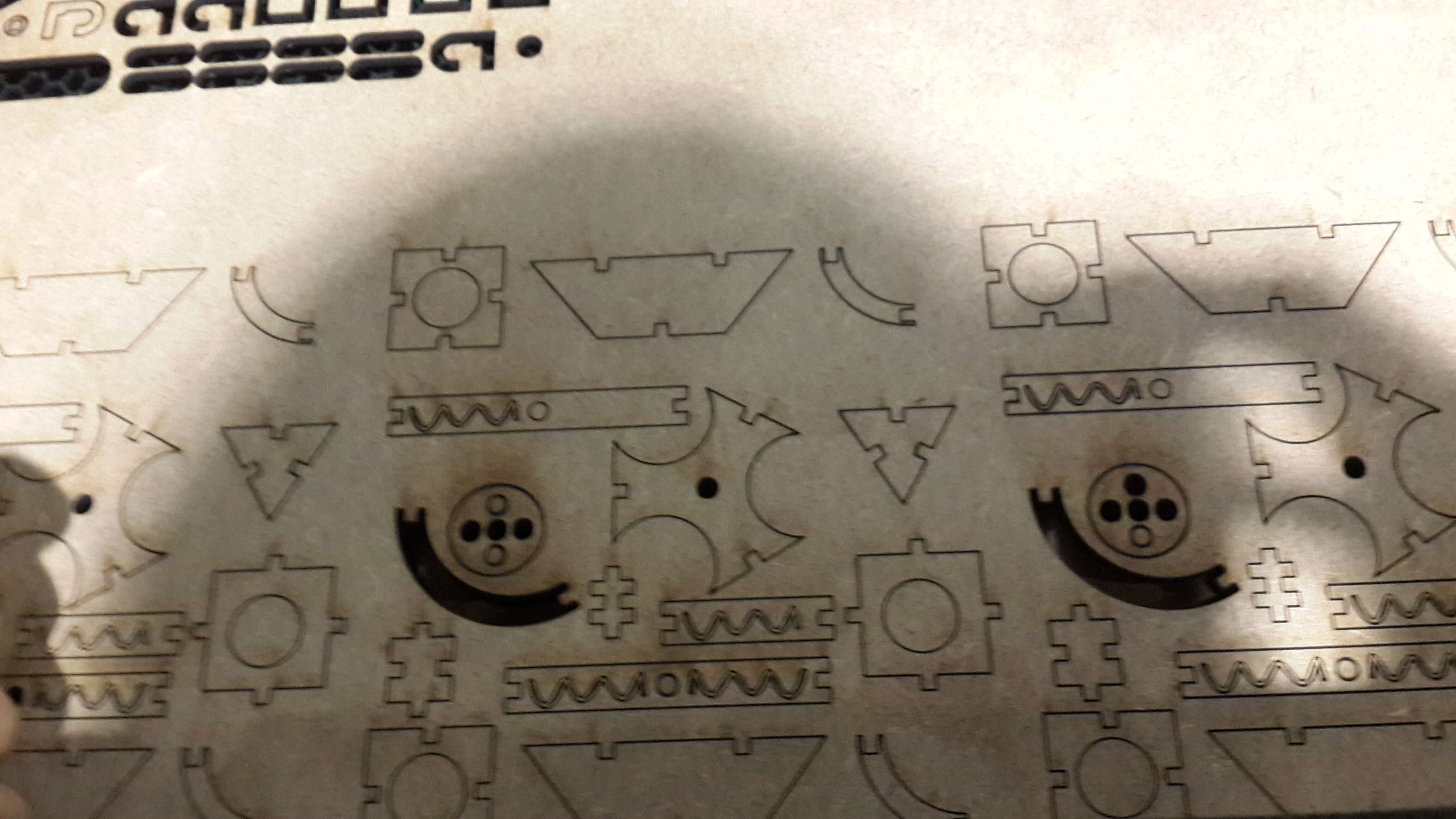
The image bellow show the pieces printed for building the hand.
Making a Pressfit Kit 2
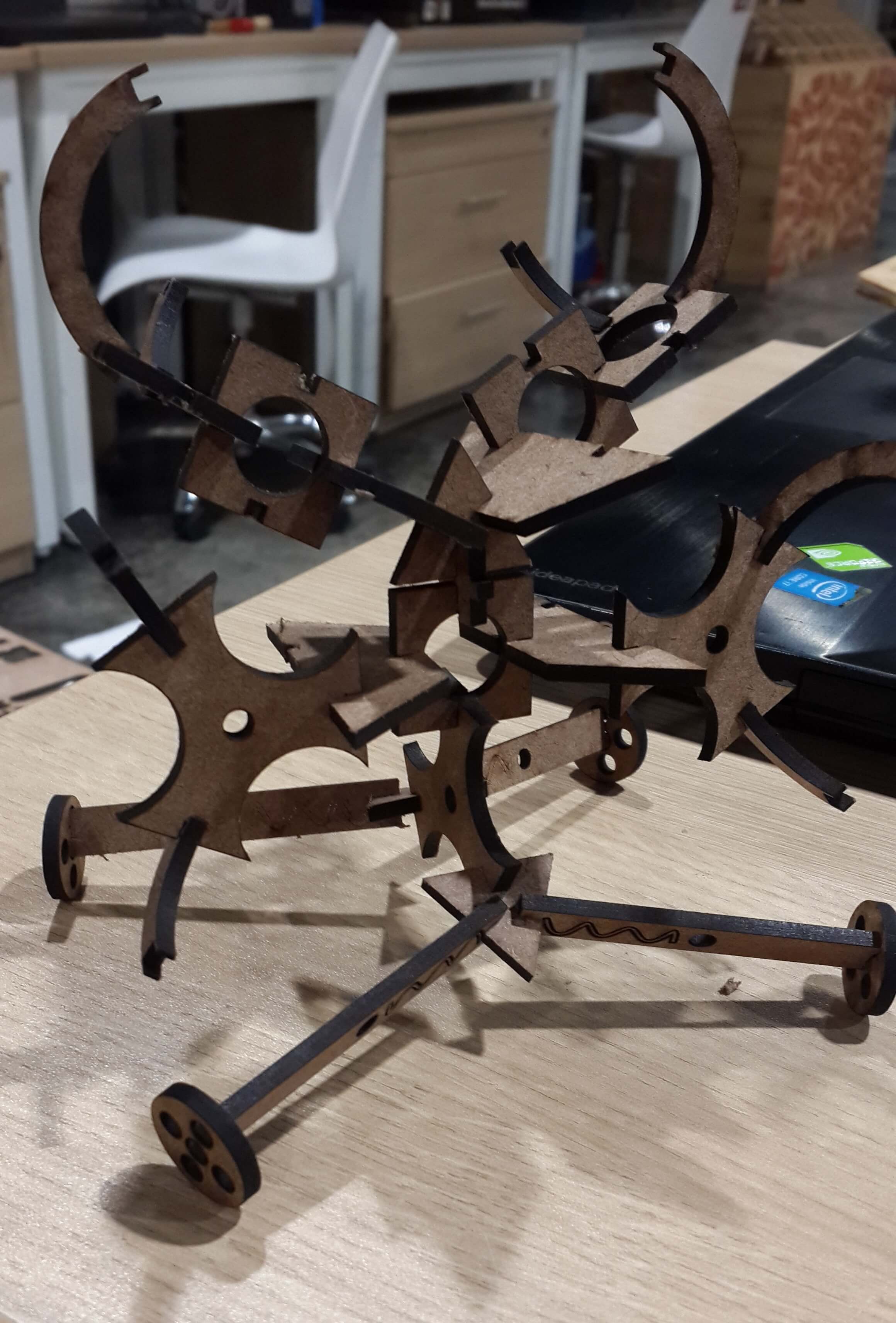
One more time, I built a bunch of different pieces in Fusion 360 for a making a modular wich can be rebuilt in different forms. .The Steps I followed were the next ones:1. In fusion 360 sketch all the pieces in one sketch, I did it this way since this time and not one on a new component, since I did not need to join them virtually.
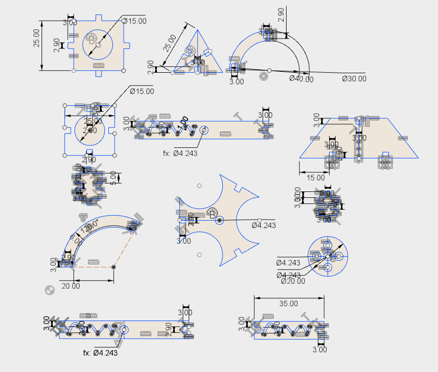
These are the pieces printed: