Computer Aided Design
For this assigment, we have to:
- (DONE) Model (draw, render, animate, simulate, ...) a possible final project, and post it on your class page with original 2D and 3D files.
All the files created for this assigment can be found on the link bellow:
---> DOWNLOAD FILES<---
Have you:
- Modelled experimental objects/part of a possible project in 2D and 3D software
--> yes
- Shown how you did it with words/images/screenshots?
--> yes
- Included your original design files?
--> yes
Introduction
My project consists on making a robotic hand, so it is basically 3D modelling, so im going to make some parts related to my project in 3D, a general sketch of my project in 2D and follow a tutorial for 2D. The softwares I used are:
- Inkscape
- Rhinoceros+Grasshopper
- Fusion360
.
Working With GIMP
GIMP is an open-sourced (GNU Licensed) raster graphics (bit map) editor, in wich you can edit images by modifying its bitmap.
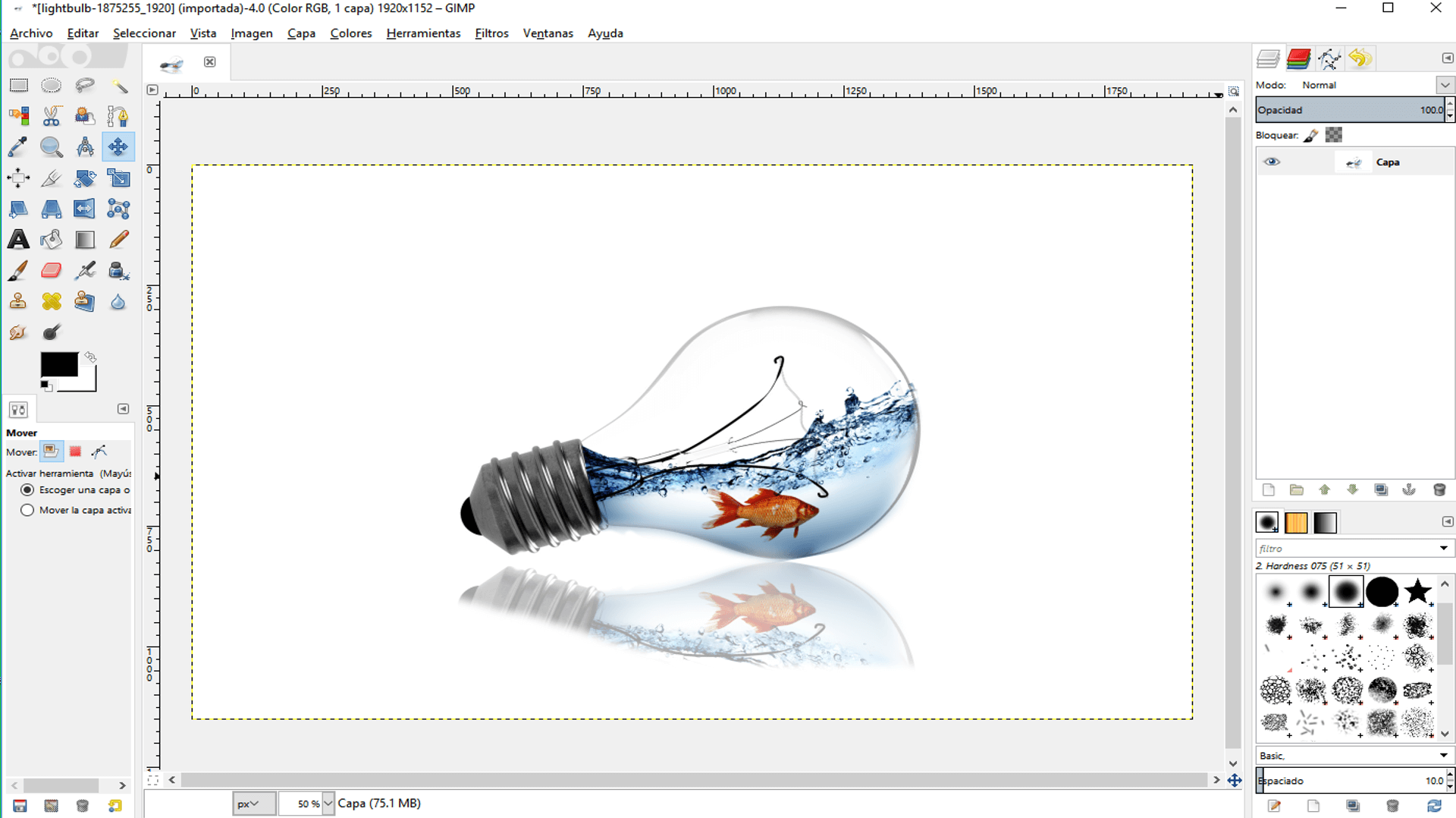
For working with GIMP, I followed this tutorial for making a lightbulb fishtank. This are the steps I did:
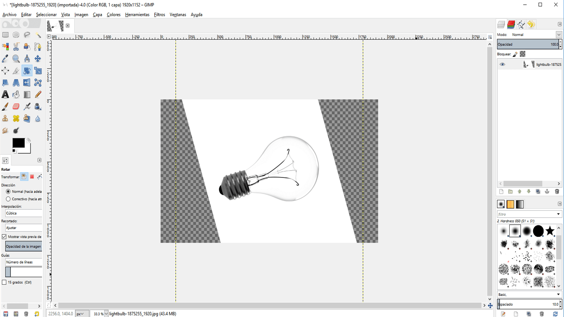
1. First, I loaded a lightbulb image
2. Then, I rotated the image with the rotation tool until it looks that its over a surface .
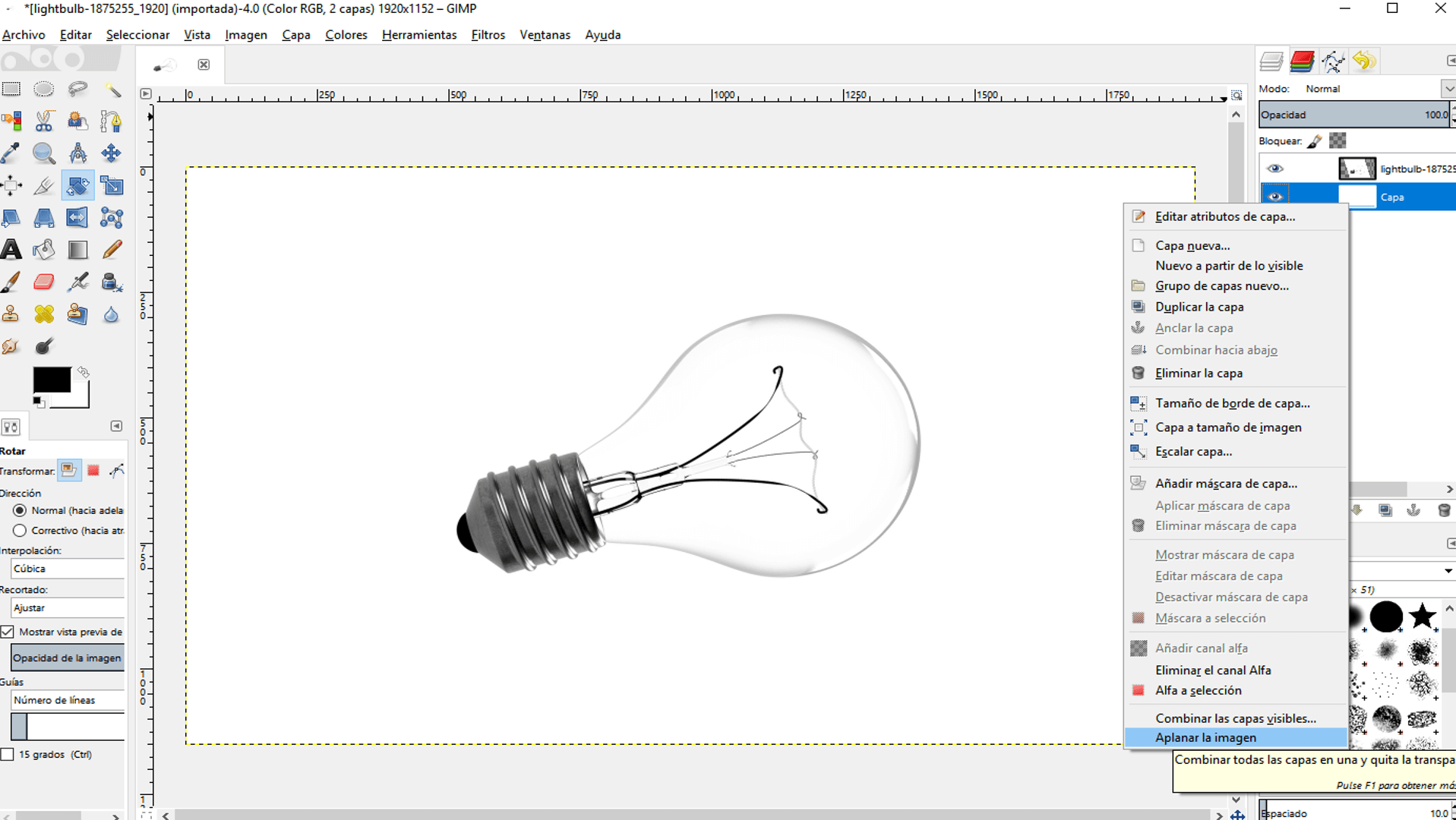
3. I filled the transparent parts of the image by creating a new white layer, putting it under the original layer, mixing both layers by right clicking on the white layer and selecting flatten image.
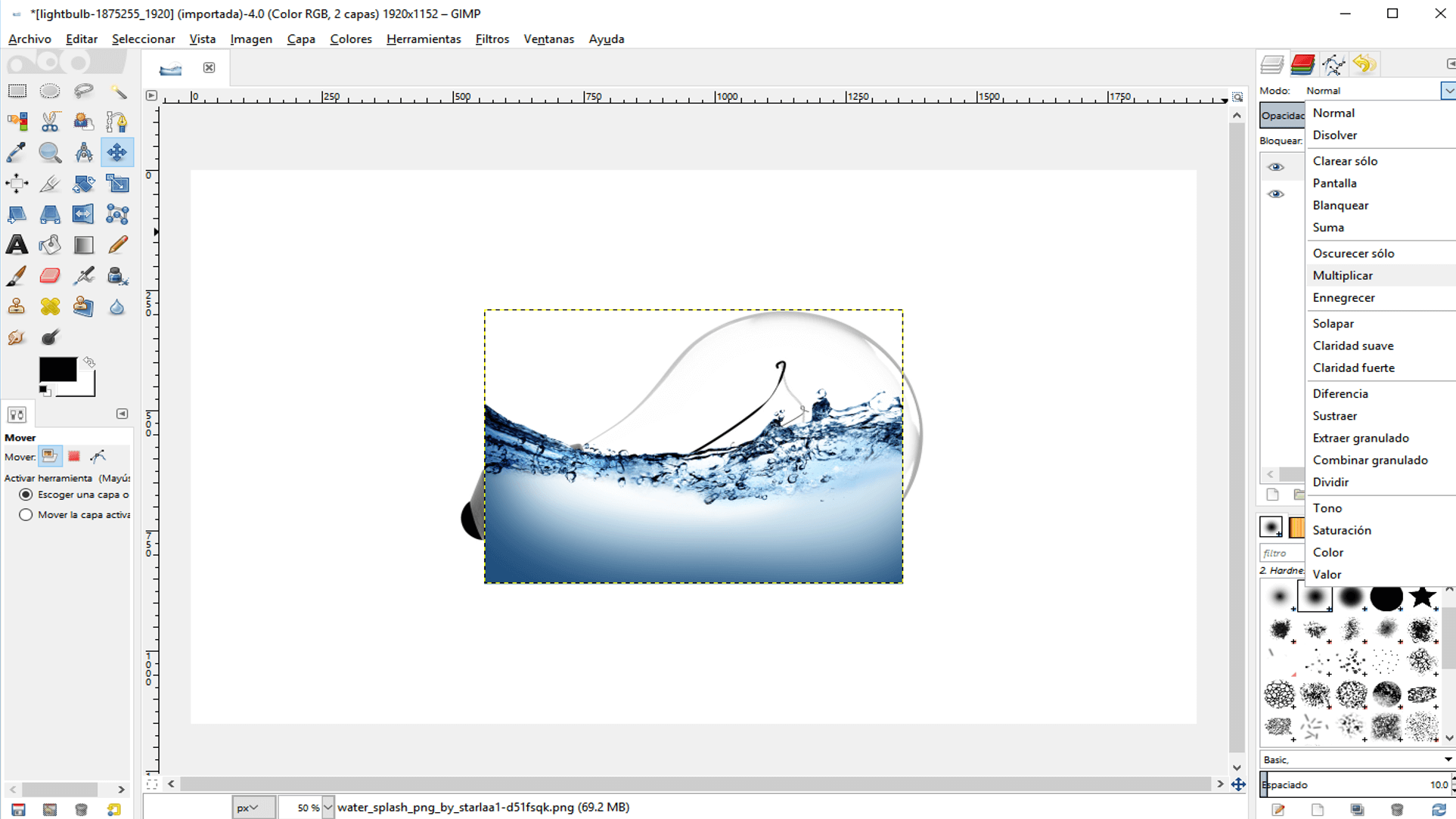
4. Then, I loaded a water image as a new layer
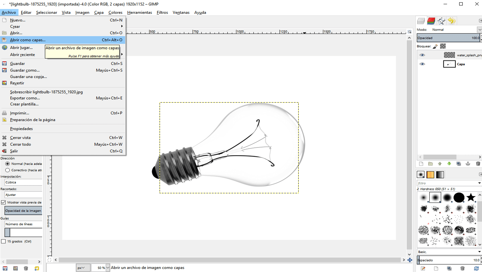
5. I went to the mode dropdown menu and selected multiply. This multiplied the bits from the original layer with the bits of the loaded layer and permitted to see features of both images.
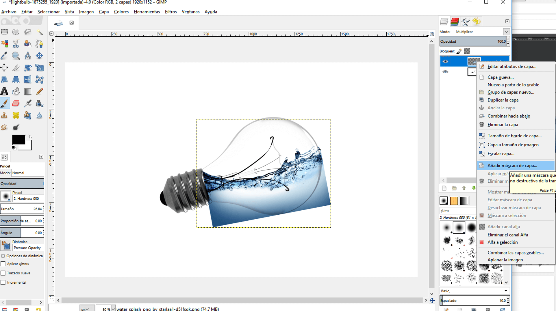
6. Then, I scaled down the water image with the scale tool until it fitted inside the lightbulb and rotated it a little, so that it looked that the watter was splashing inside the bulb.

7. I right clicked on the water layer and then clicked on create a new mask layer and selected white. This created a white layer over the water layer with a black background (not seen), so if this image was brushed with black the background covered the original image and seemed that was ereasing it.
8. I selected the brush tool and the black color and then bruched the outside of the bulb until there was no more water outside the bulb.
9. I loaded the fish image as a new layer, scaled it down and then moved it inside the bulb
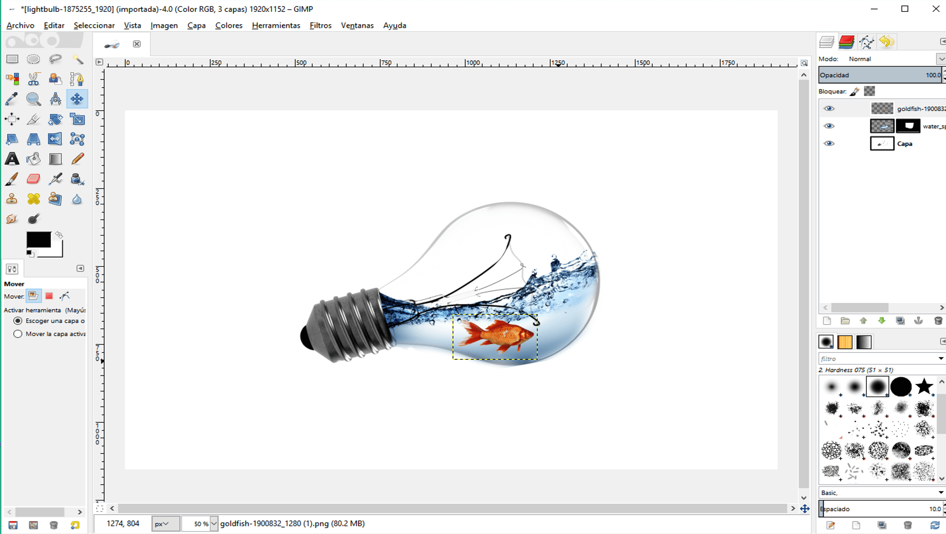
10. Then, I chose multiply to combine the fish image with the water image and flattened the image.
11. I added a reflection to the image by copying the resulting layer and flipping it vertically.
12. Then, I chose multiply and putted the reflection under the image.
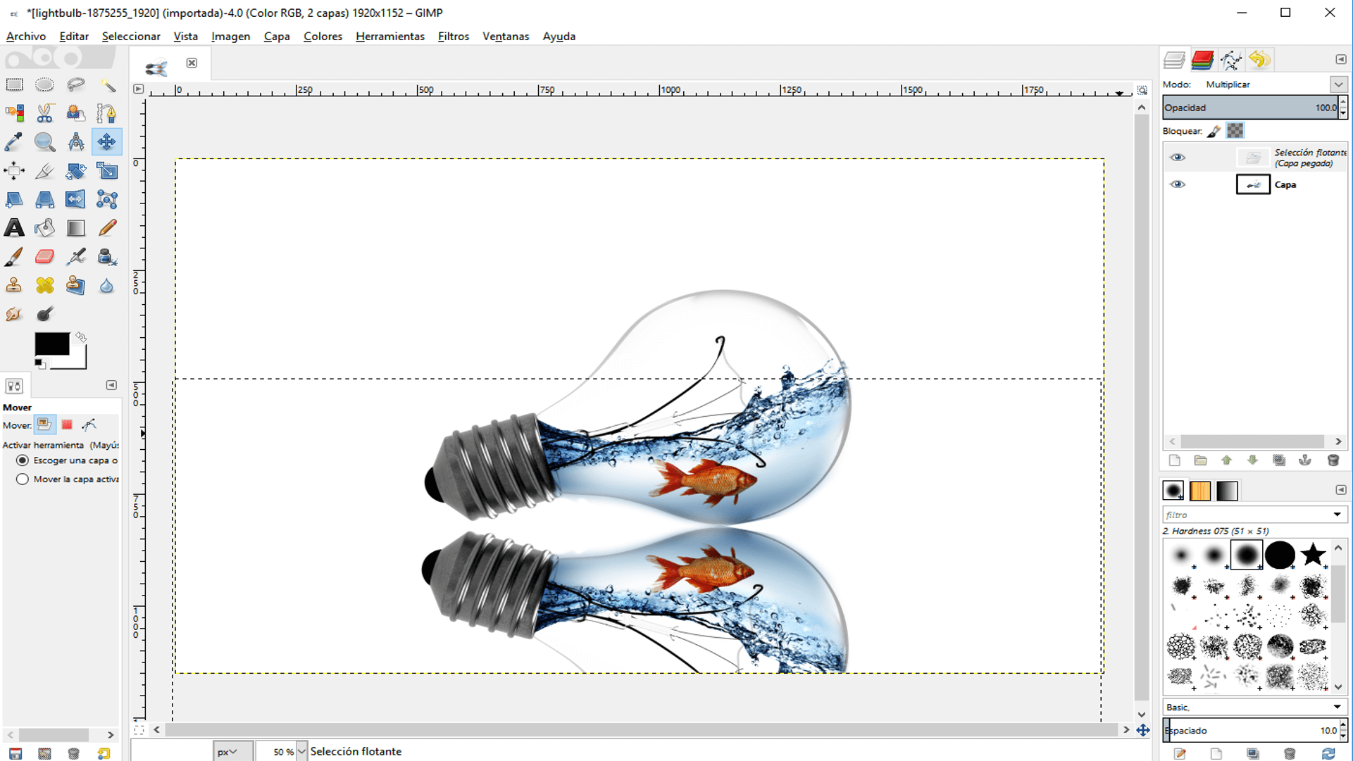
13. I changed its oppacity and erased parts of the reflection.
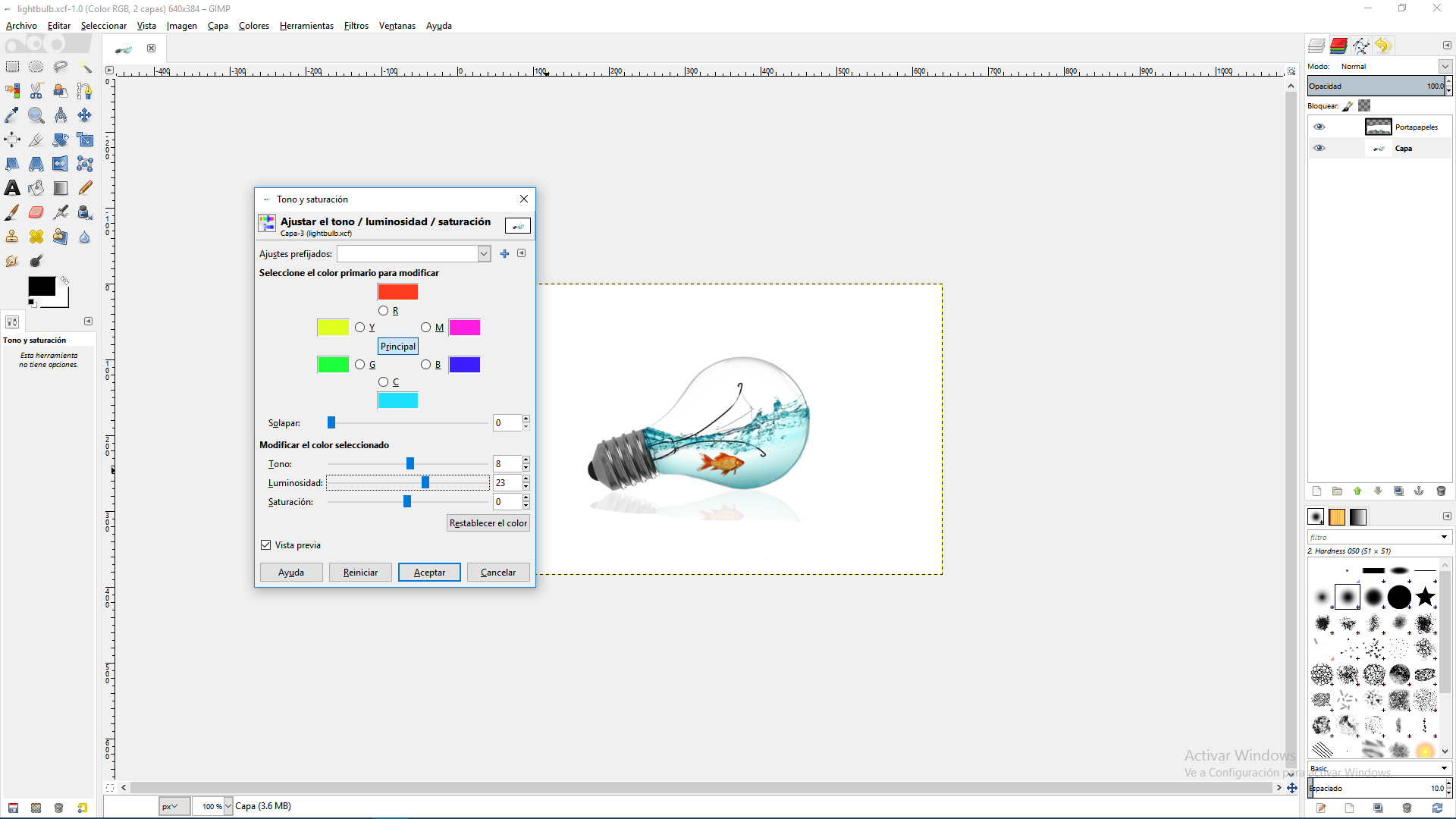
14. Finally, I changed the colors with the hue-saturation option on the color menu.
Working With Inkscape
Inkscape is an open sourced (GNU Licensed) vector graphics editor. In which you can edit vectorized images (which do not depend on bits, since its features are defined by mathematical equations).
For working with Inkscape, I sketched a general explanation of my project. This are the steps I did:
1. First, I draw a rectangle and a circle on the base of it. And by using the command union, I make them a unique figure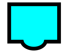
2. Then, I drew some elipsoids which represented the phalanx of the fingers
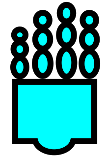
3. I drew the thumb by drawing a couple of elipsoids and rotate one of them by double clicking it

4. I drew the arm by making union of an ellipsoid and a rectangle
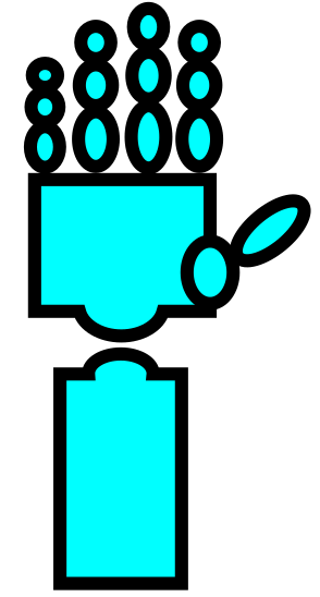
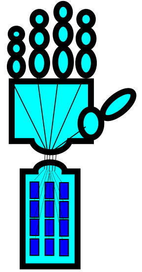
5. I drew some rectangles inside the arm, which represent some motors; and some lines, which represent the threads that are going to pull the fingers.
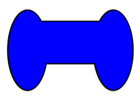
6. I drew the shape of a controll by making union of two ellipsoids and a rectangle.
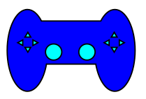
7. I drew some triangles on the control for representing some buttons and a couple of circles for representing joysticks.
8. Finally, I drew some lines that represent wireless waves and added some text
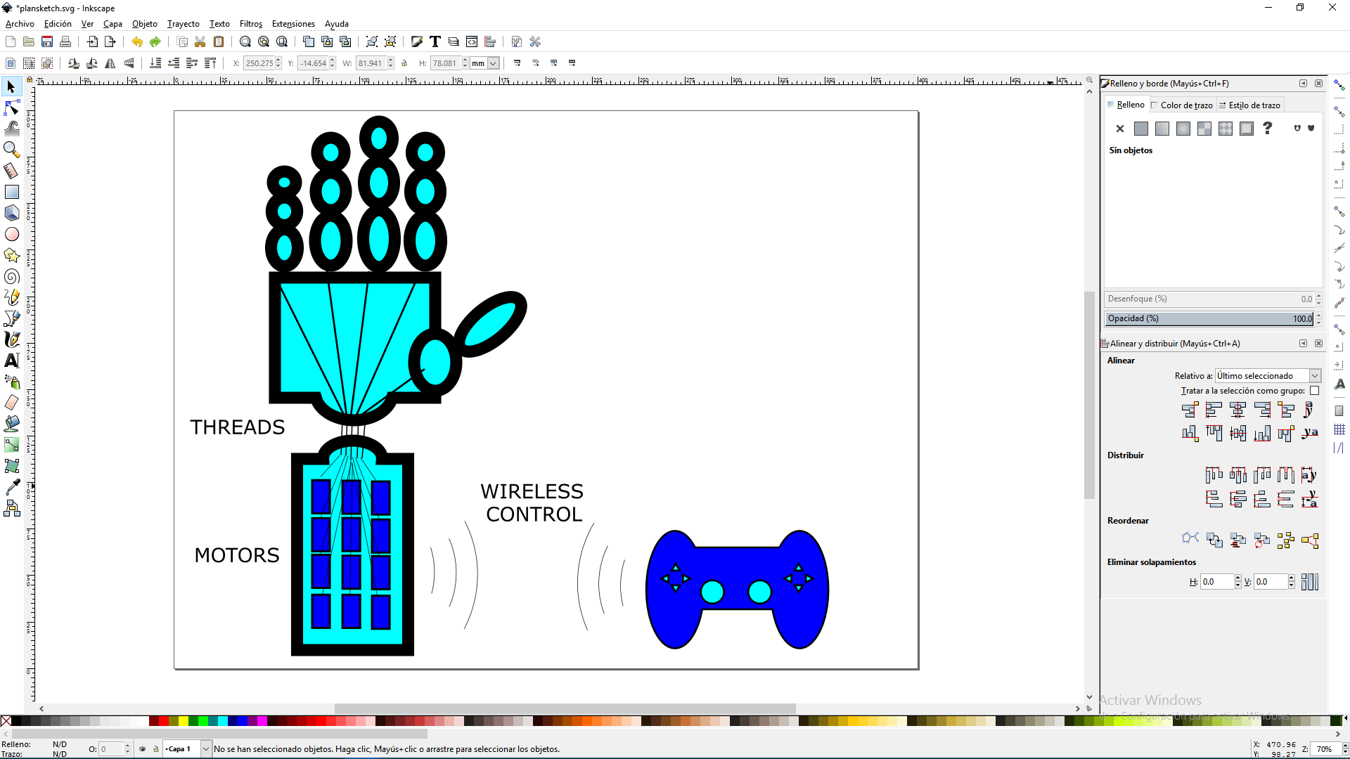
After following the instructions, i got the same image and made it some changes.
The resulting image and the necessary files for its development can be downloaded here
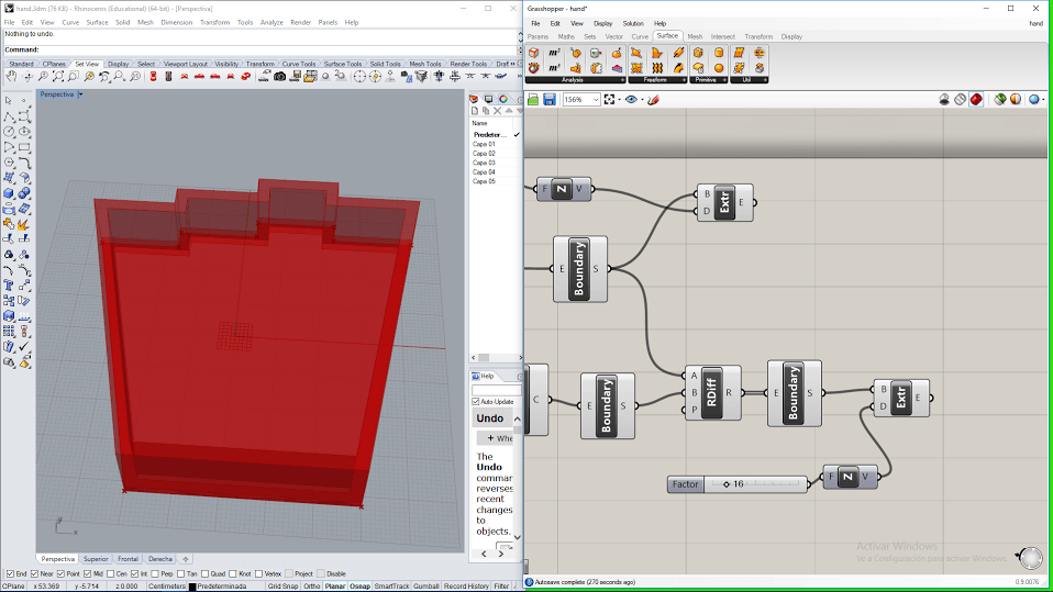
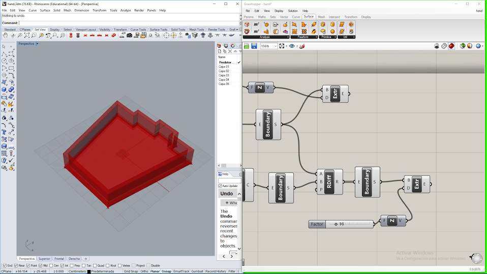
Working With Grasshopper
Grasshopper is a plugin for Rhinoceros 3D, which permits to create objects on Rhinoceros by visual programming language, For testing Grasshopper, I decided to model the base of a hand. In general this are the steps y did:
1. First, I drew a single point in Rhinoceros and then wrote _Grasshopper on the command bar
2. Then, on the window that appeared, I dragged a point block from the top bar, right clicked over it, chose "set one point".
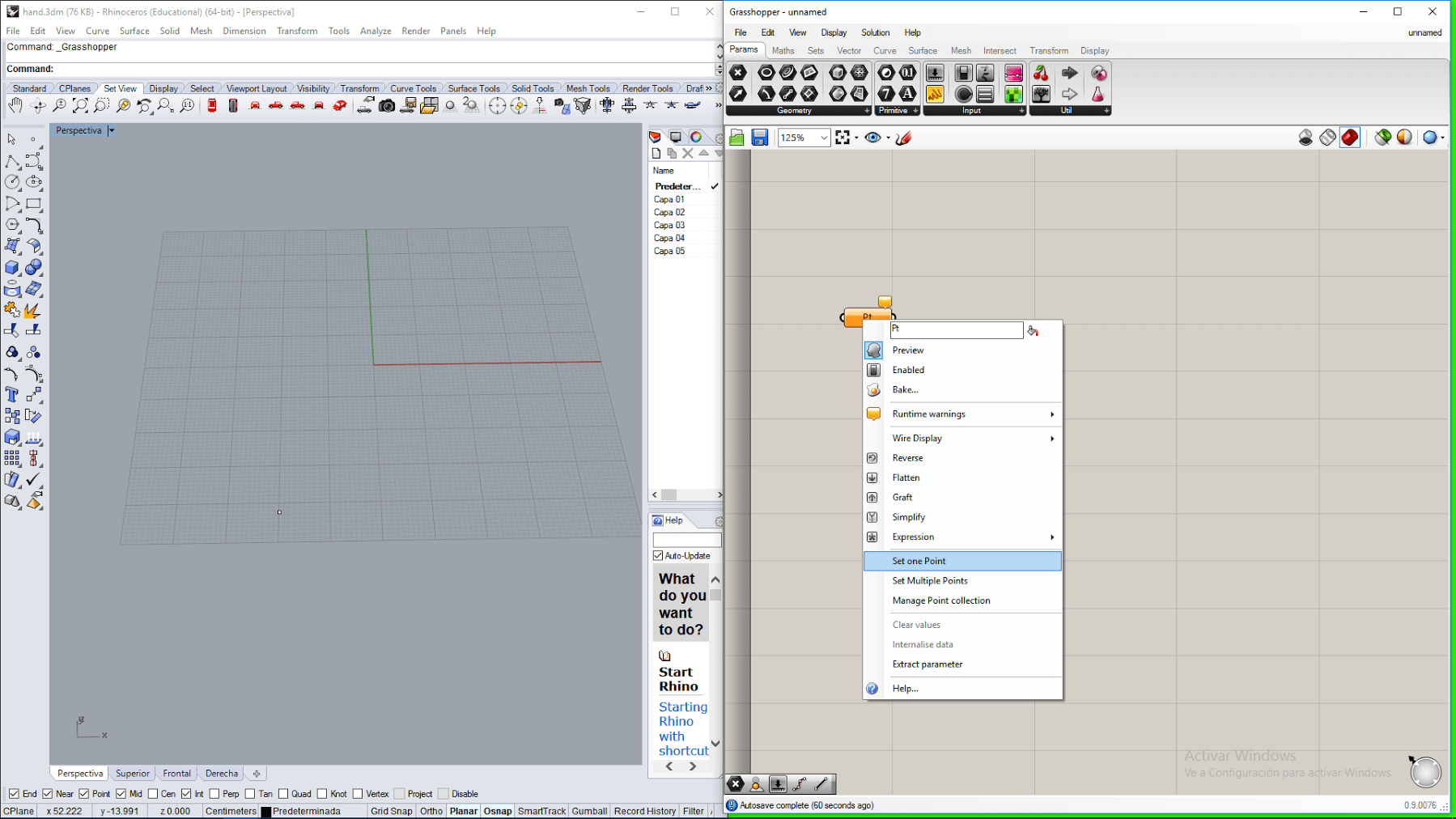
3. Then, I clicked over the point previously created on the Rhinoceros IDE and the appereance of the point changed to a small cross.
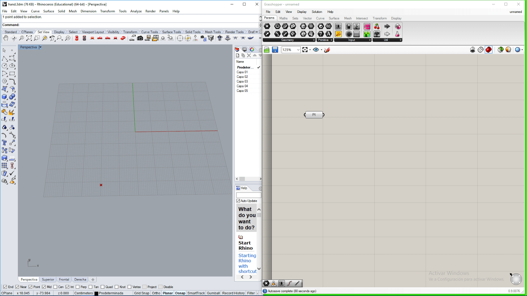
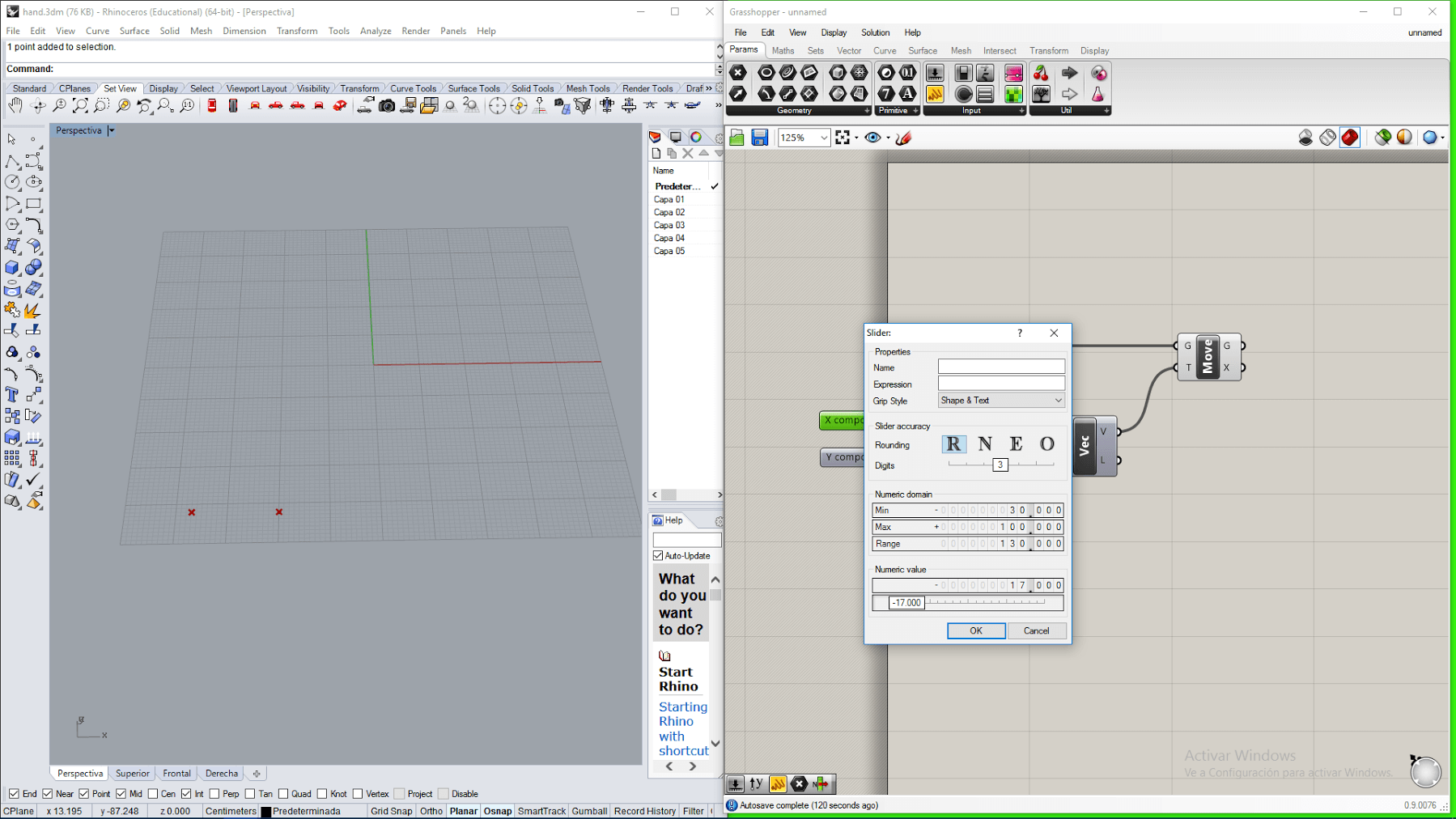
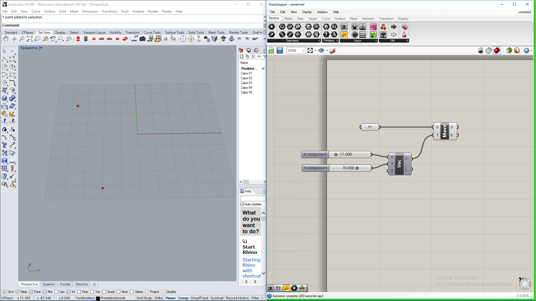
4. After that, I draged a move block on the grasshopper IDE, a vector block and a couple of sliders. And then connected them all, so that the inital point moves in the direction x and y indicated by the sliders.
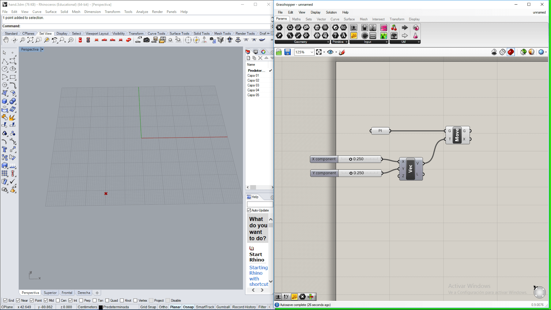
5. Then I setted the sliders to -17 and 70, so that the point moved -17 units in the direction of x axis and 70 units in the direction of y axis.
6. Then, I continued by moving the new point 20 units to the right, so that it forms the base of a finger
7. I continued moving the point until I got all the vertices that delimit the shape of the hand.
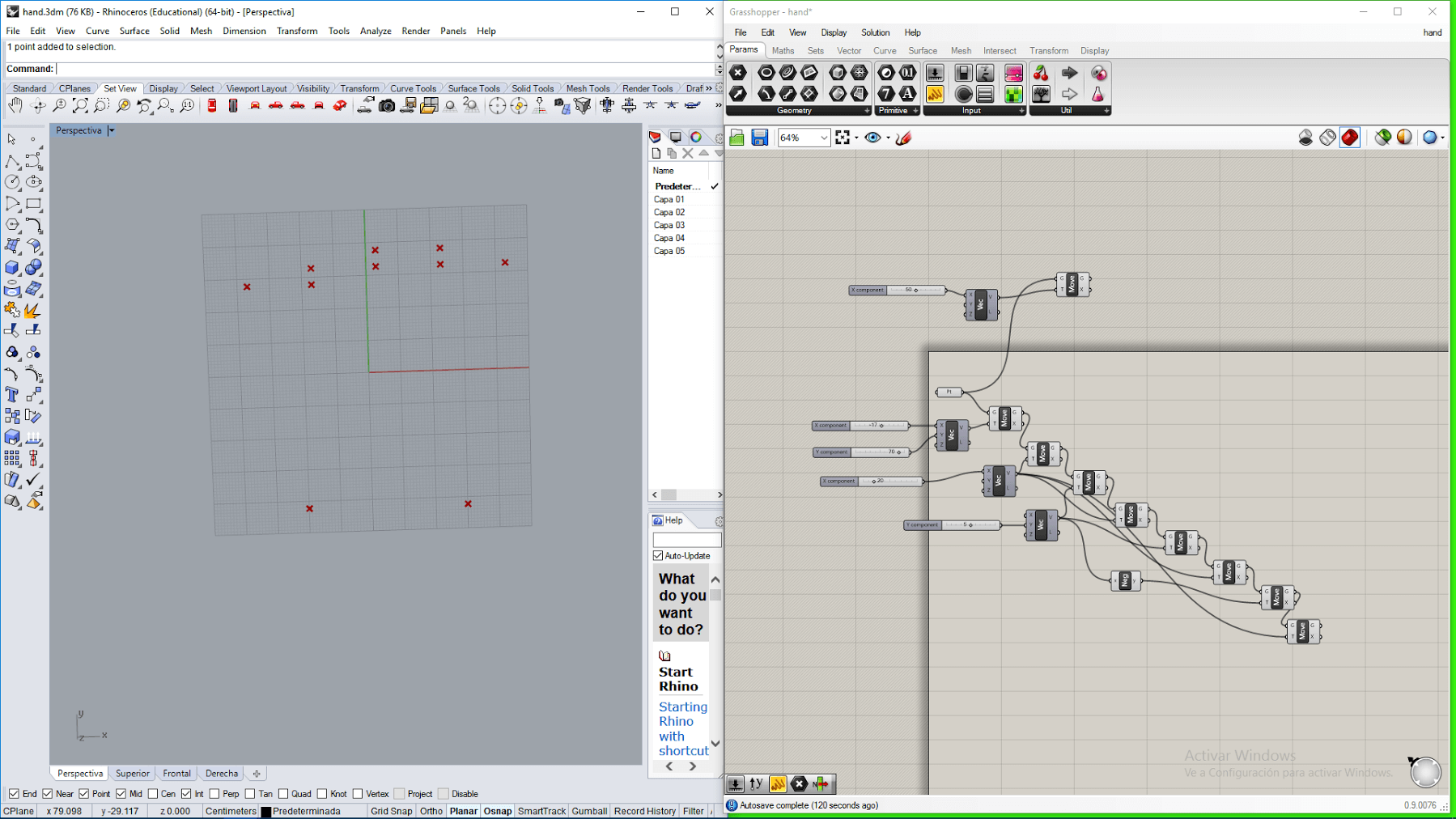
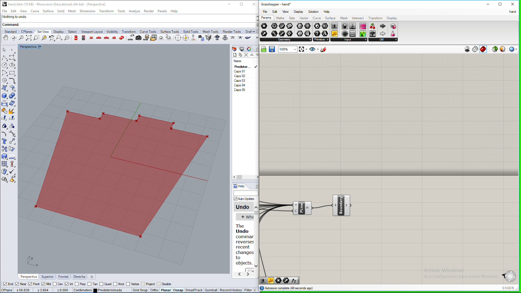
8. Then I dragged a polyline block, and attached to it all the points created in the same order in wich they were created, for doing this, I pressed shift while connecting each output to the input of the polyline block.
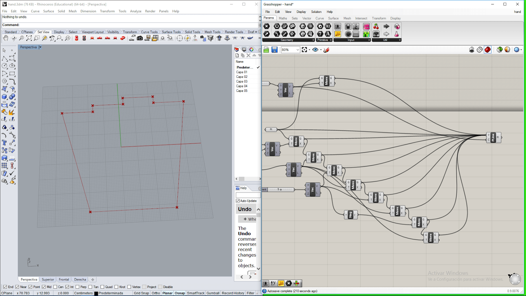
9. After that, I dragged a boundary block and connected the output of the polyline block to it. This creates a surface limited by the edges of the polyline
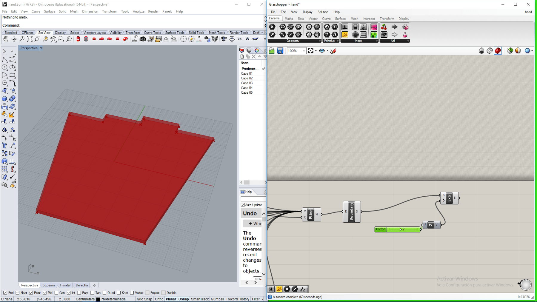
10. Then, I dragged and extrude block, a Z vector block and a slider, and connected them so that a solid is generated by a extrusion in the Z axis with a height indicated by the slider.
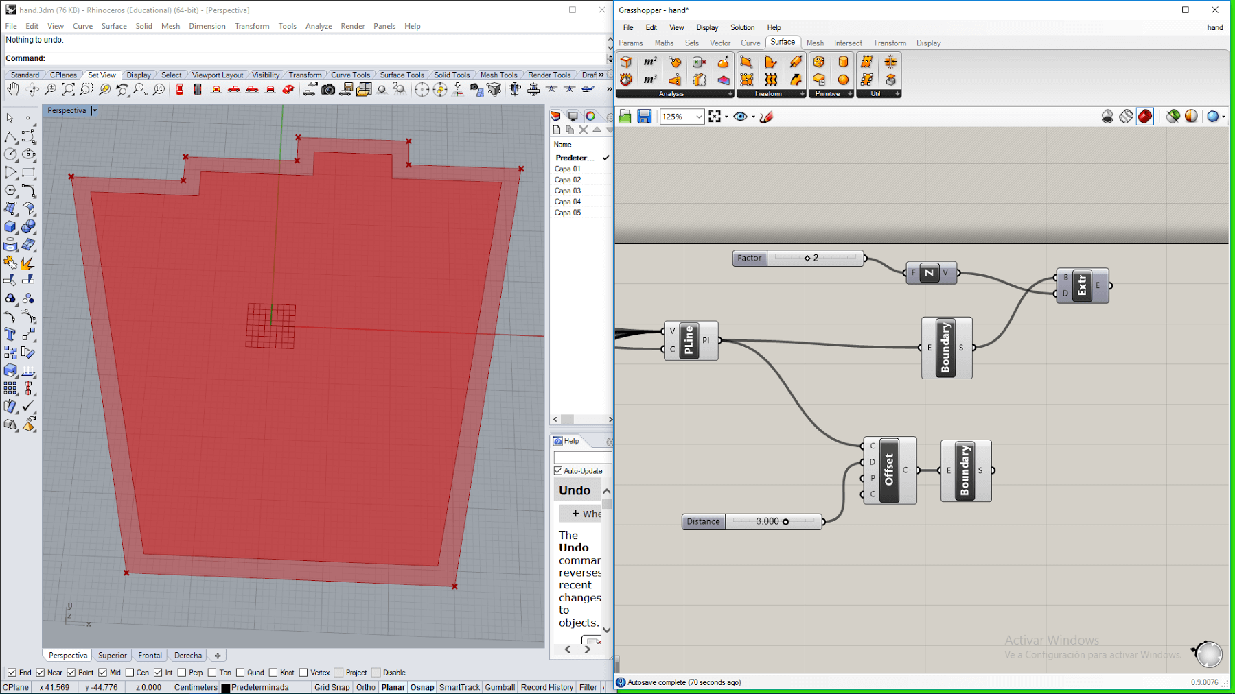
11. I dragged an offset block and connected it to the polynline, and dragged a boundary block for connecting to the output of the offsetblock. The result is a smaller surface than the base of the palm.
13. Then I differentiated the surface of the base of the palm with the smaller surface for getting the base of the walls of the palm.
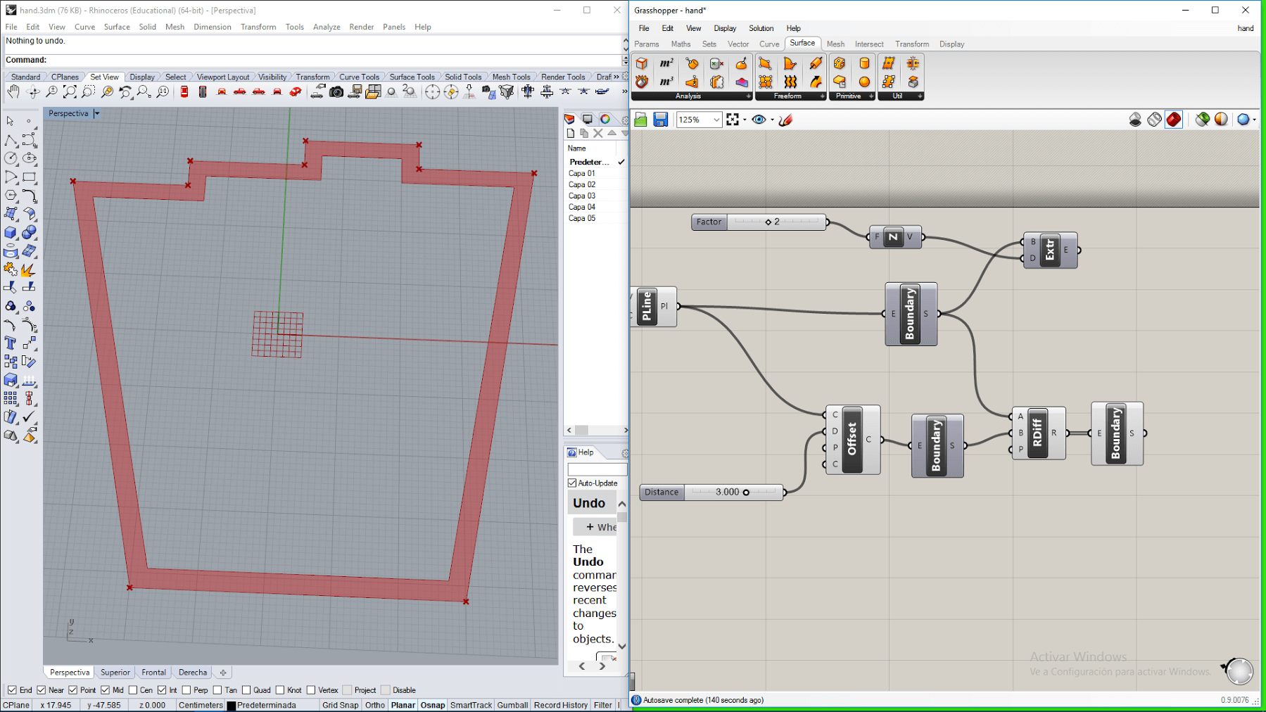
14. Finally, I dragged an extrude block, a Z vector block and slider. I connected them so that the previously generated surface was extrude in the Z direction forming the walls of the hand .
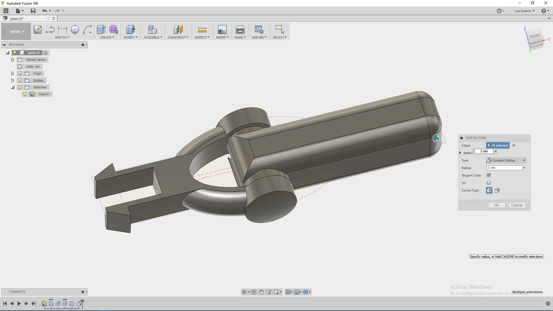
Working With Fusion 360
Finally, I worked with Fusion 360, which is a CAD, CAM and CAE tool licensed by Autodesk.
For working with Fusion 360, I tried to make a joint. This are the steps I did for developing the joint.
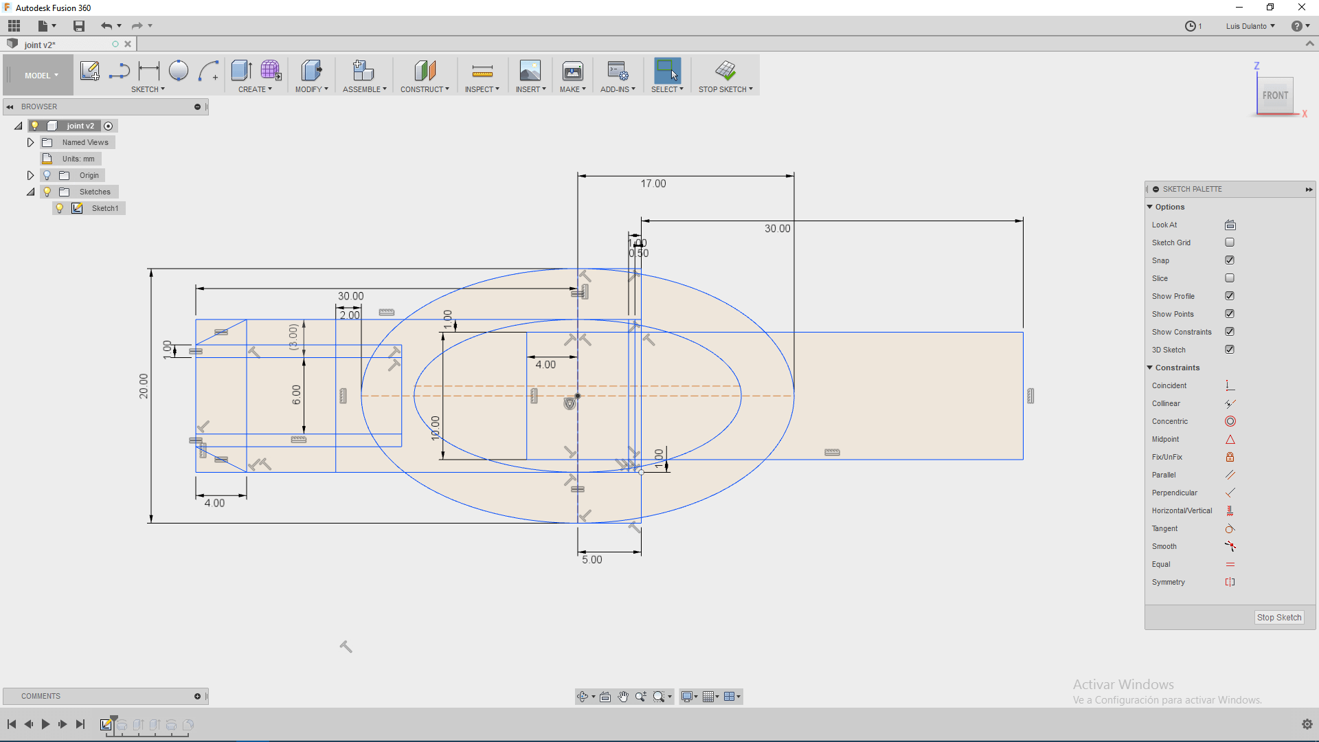
1. First, I drew a projection of the object on the front plane
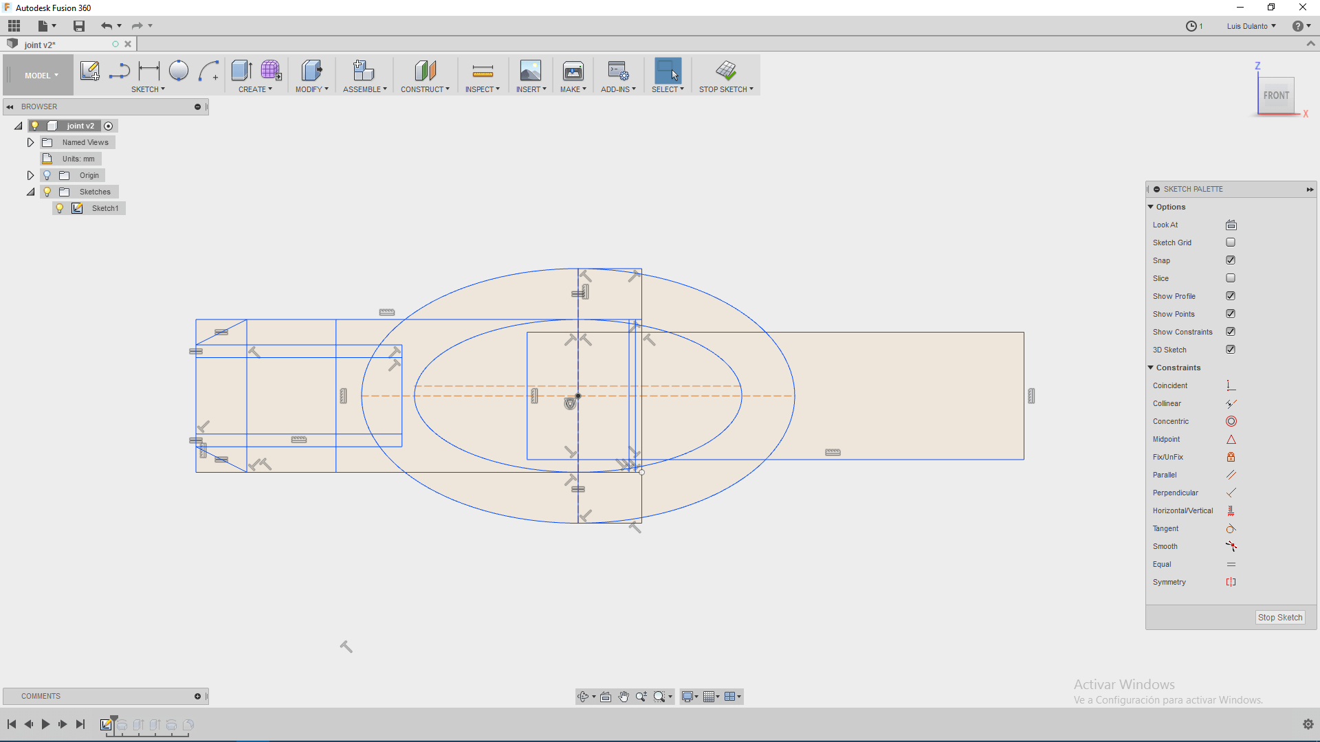
2. I started to assigne dimensions to all the lines, by clicking on sketch dimension.
3. I calculated the dimension the attatching joint, so that when the piece is compressed, the secures go inside the hole, for this I assiged to the hole the same dimension of the double of a secure (6 mm for a secure of 3mm).
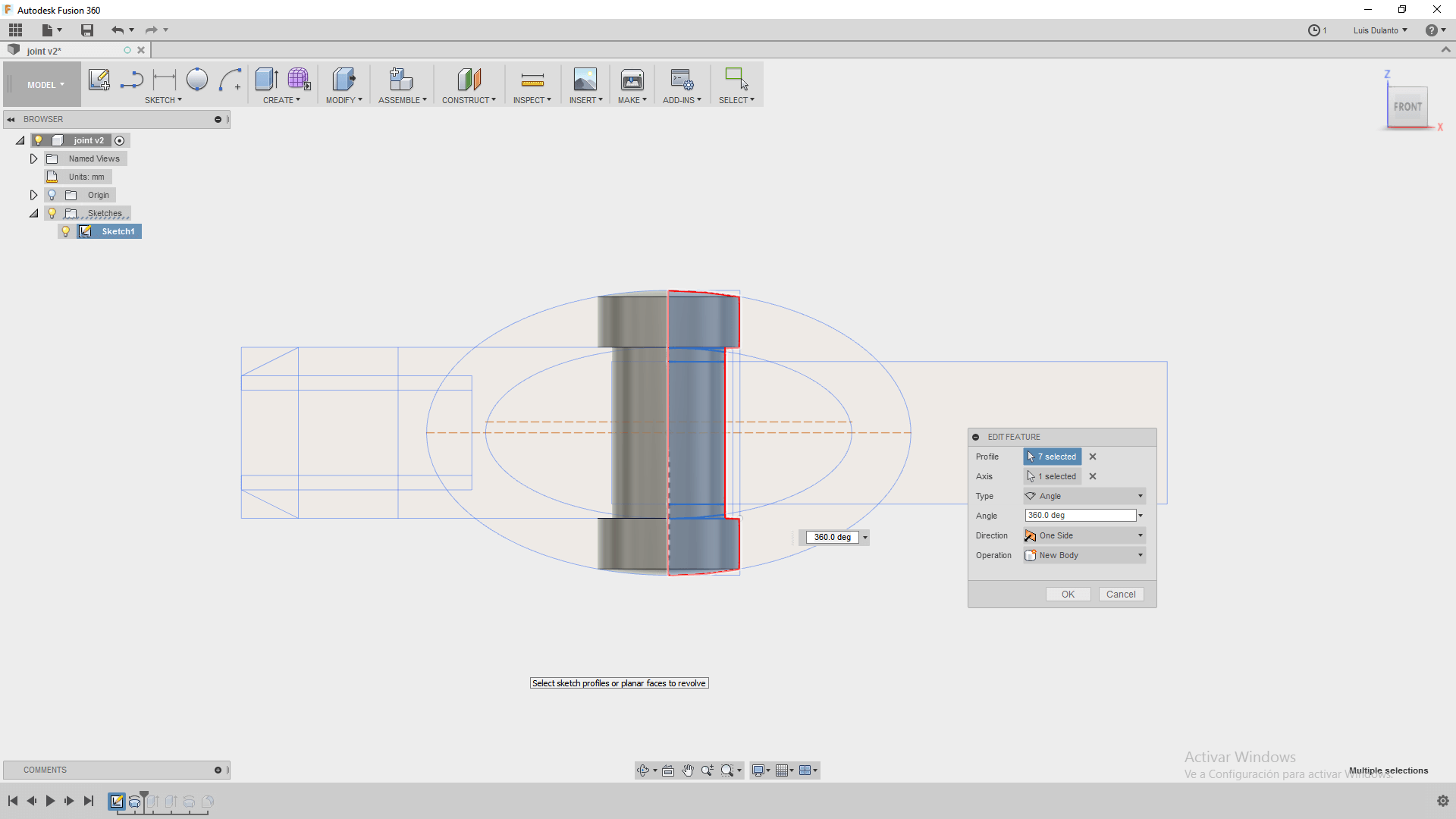
4. Then, I made a revolve (Create->revolve) operation on part of the sketch for making the base for a cilindrical joint .
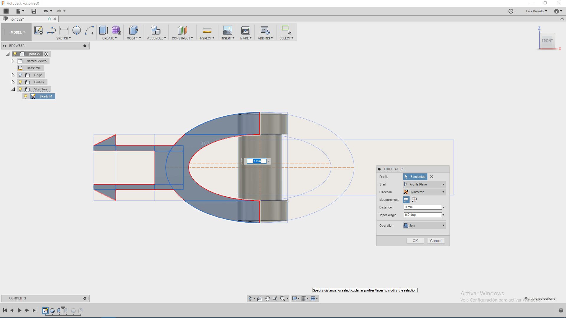
5. Then, I extrude out the rest piece which consisted on a joint for attatching to a body.
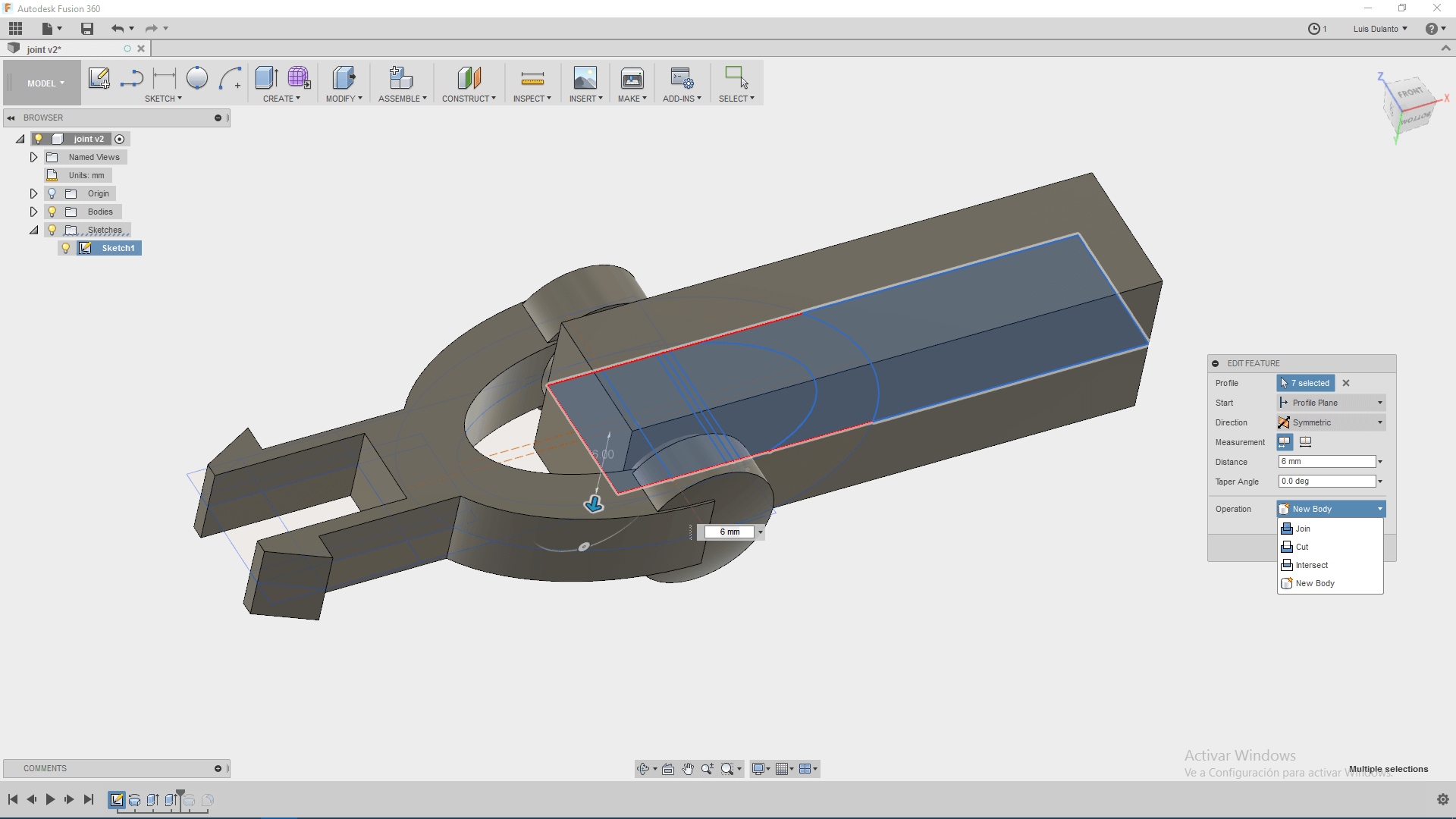
6. After that, I extrude out the second piece as one new body, this piece overlapped the second piece
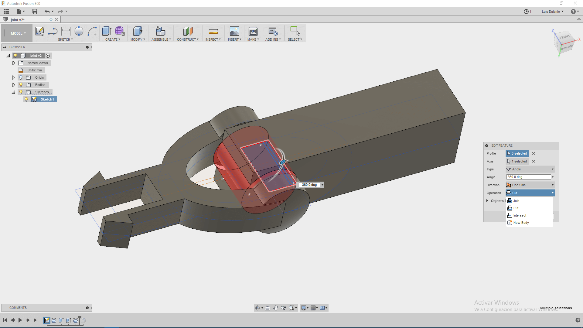
7. So, applied a revolve operation for cutting part of the new solid so that it dont overlaps to the first piece.
8. Finally, I applied a fillet operation for roundindg the sharp edeges of both pieces