Assignment 13
Input Devices
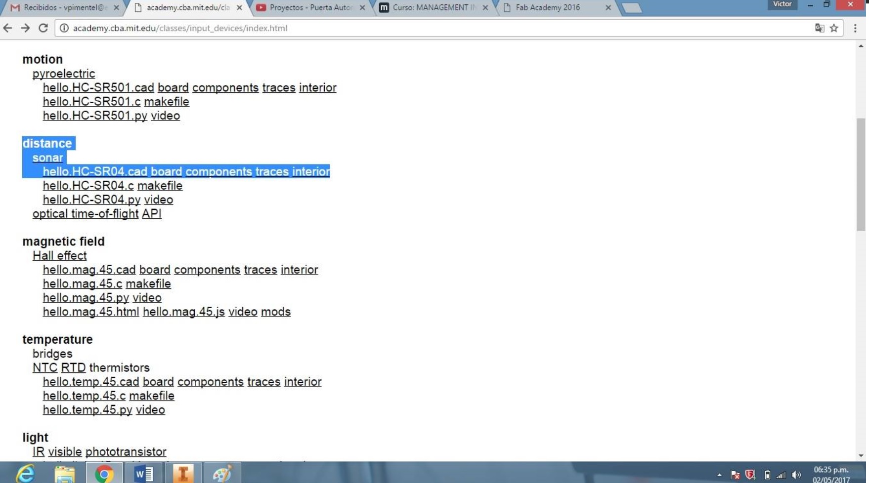
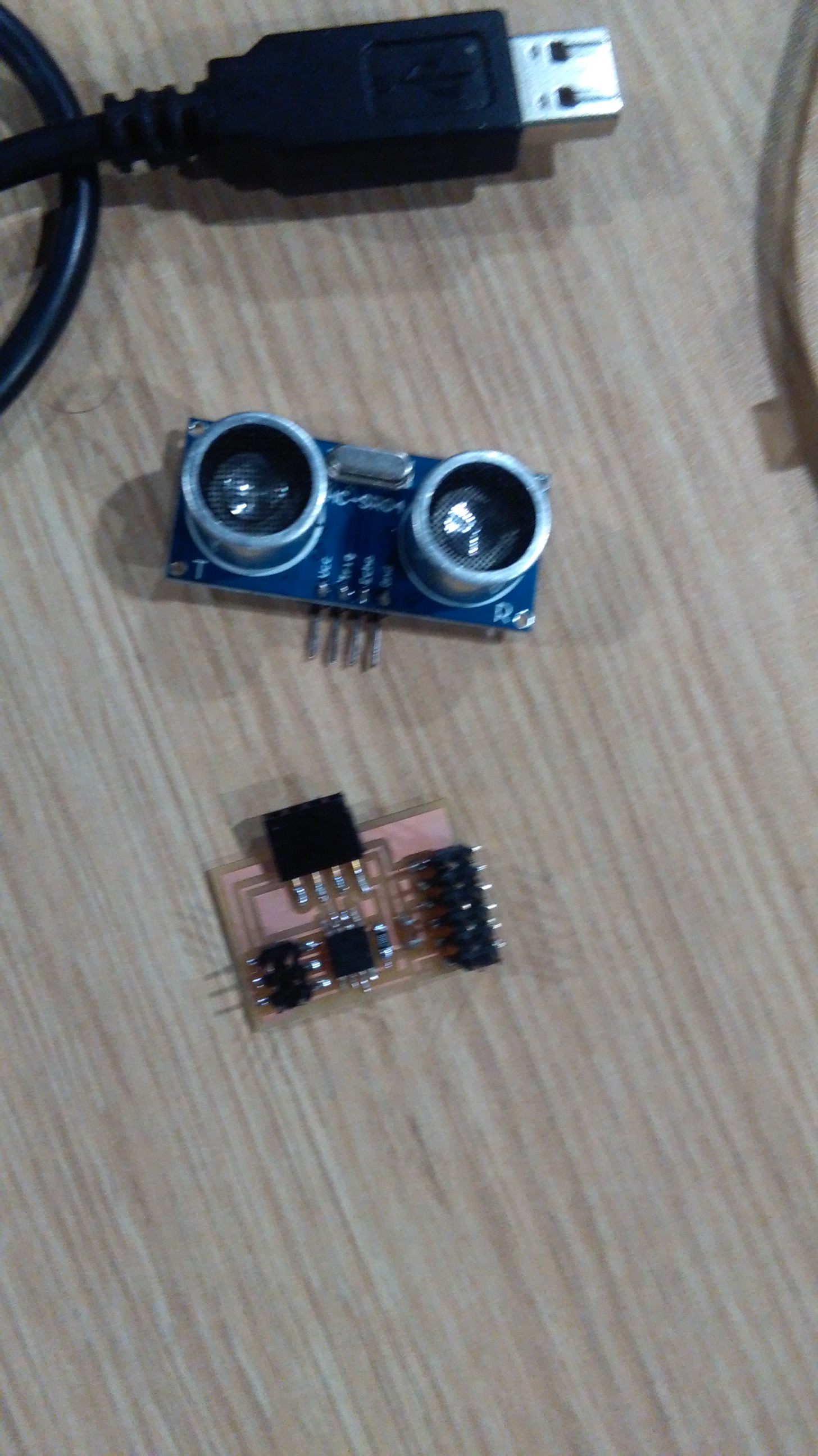
I decided to make a board for Ultrasound, which I would need for my final project, if I consider measuring the front distance for a Kart.
First, I download the board to mill the schedule.
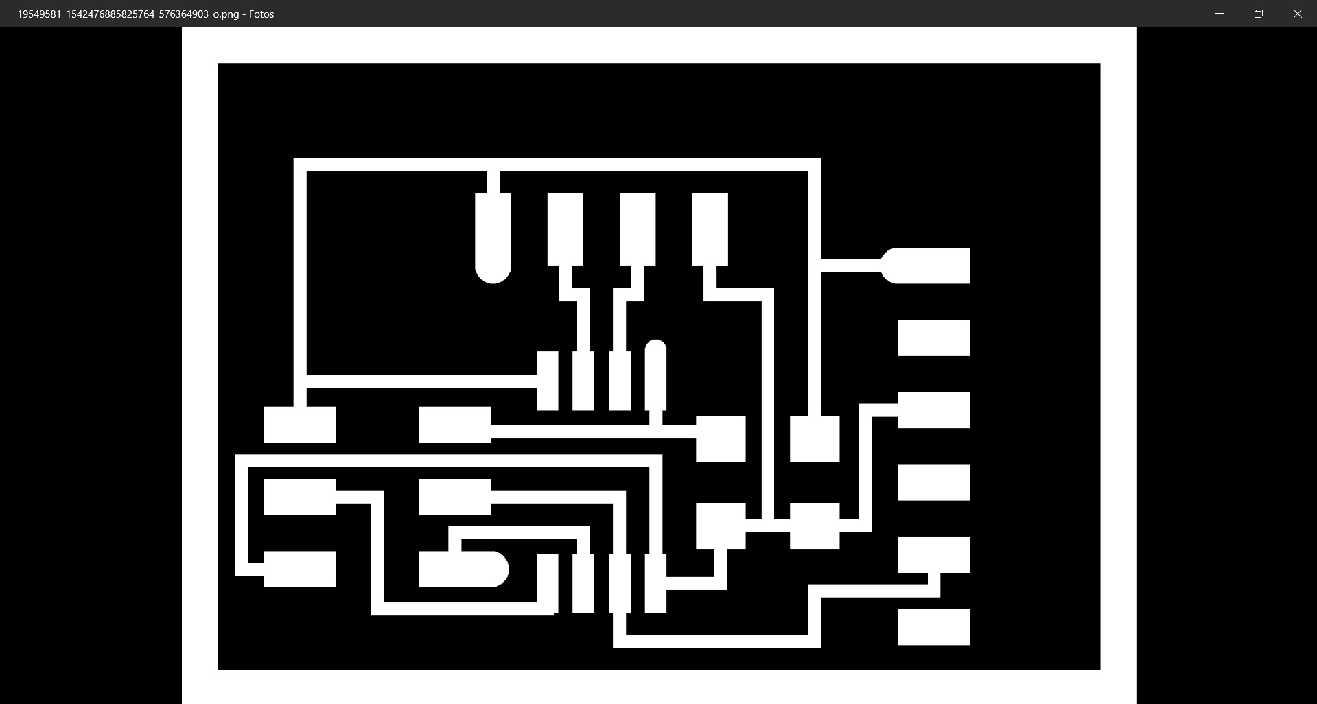
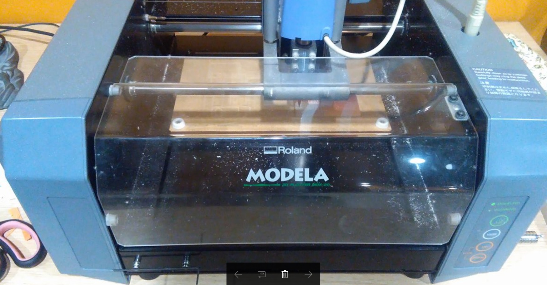
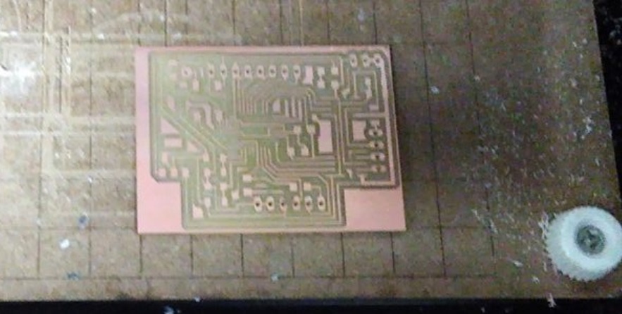
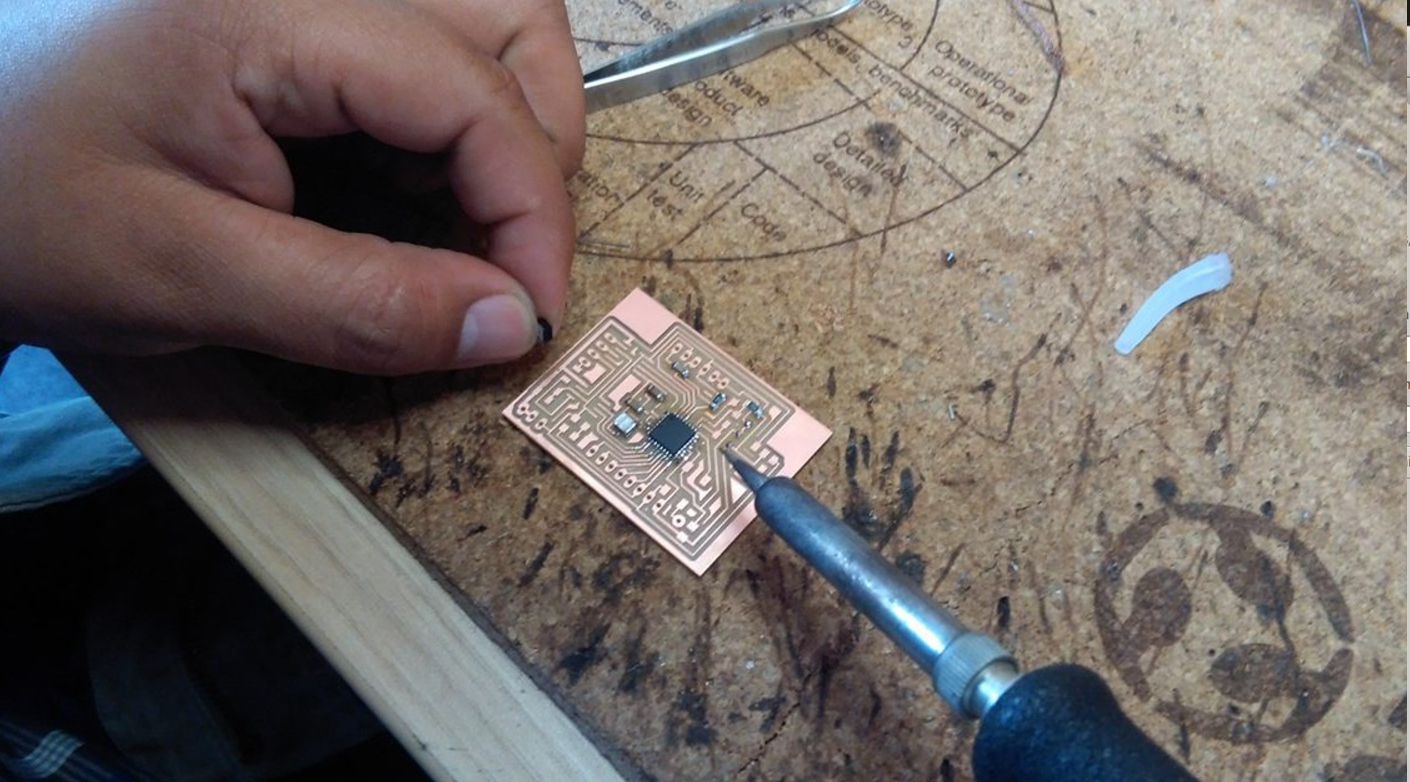
Then we milled him in the modela, and we got the board.
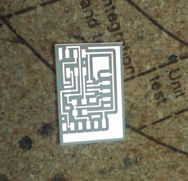
Then the required header pins and Attiny are soldered for the ultrasound
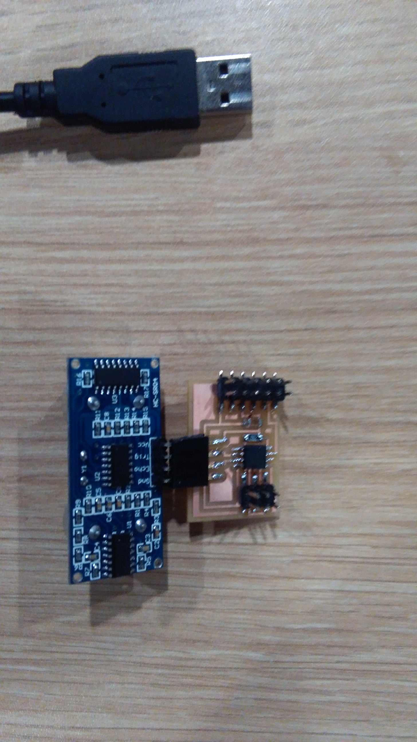
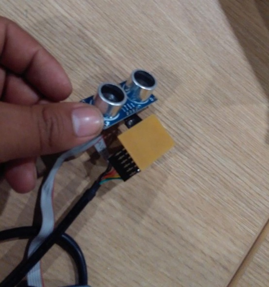
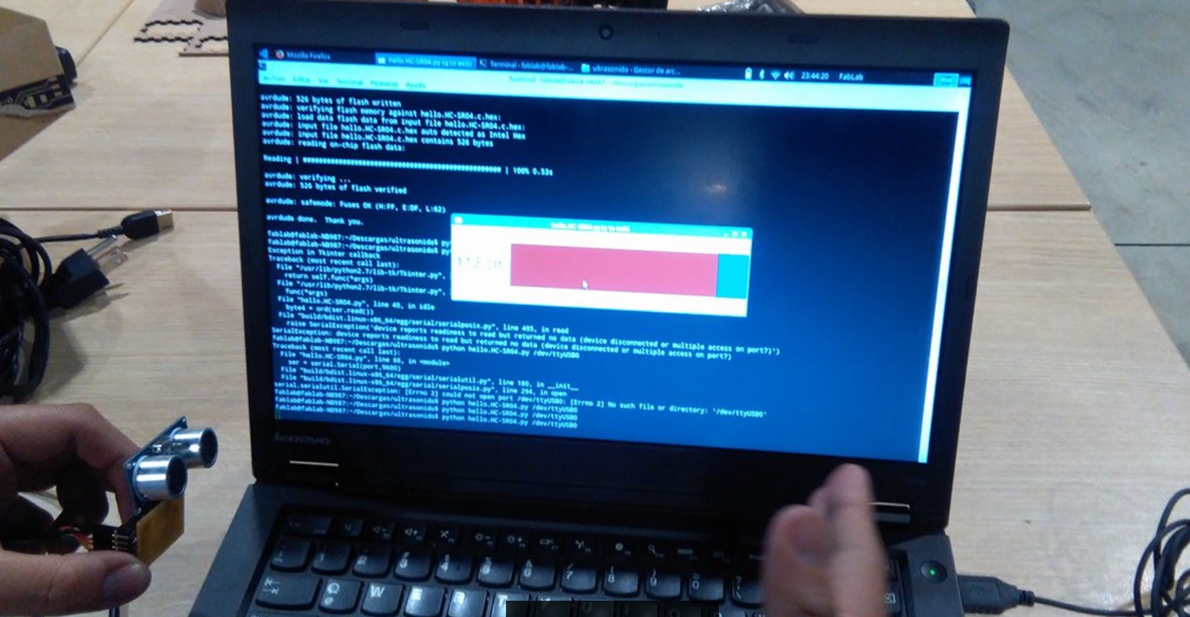
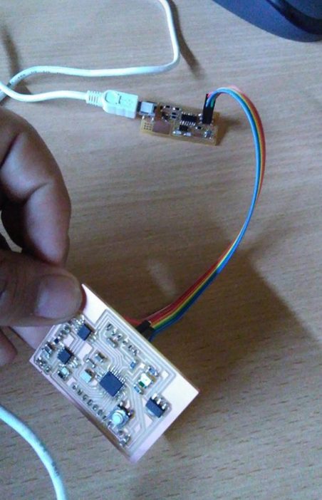
Finally , I use the code found in the schedule to program the UltraSound And I was able to run the Input.
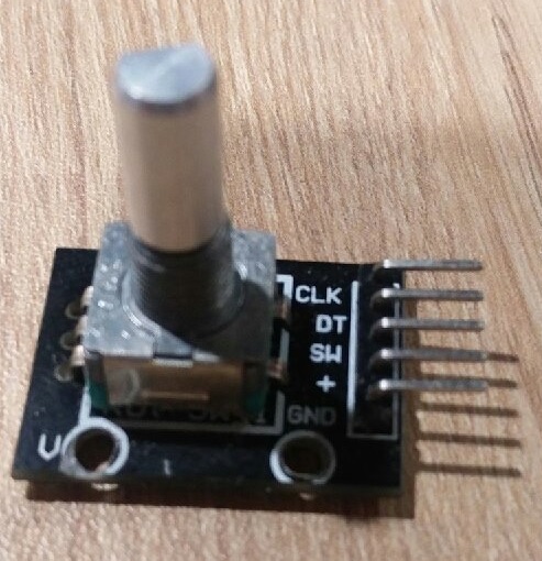
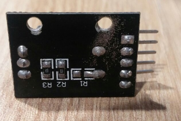
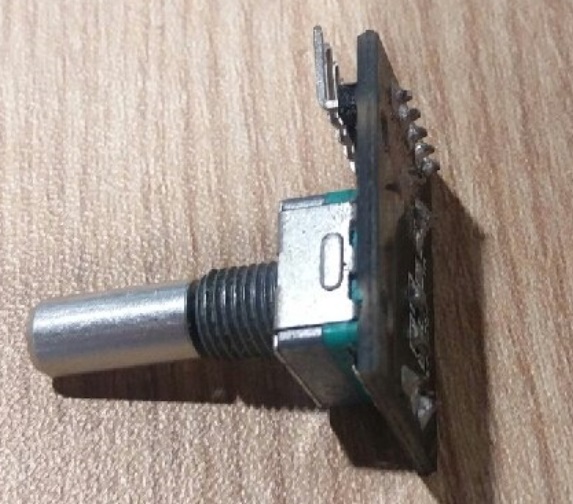
Encoder
As an advance for my final project, I started to make my board or board for an ENCODER that I will use to be able to measure the speed of the revolutions that the motor shaft rotates.
Then, first design the board in Eagle to be able to solder the component.
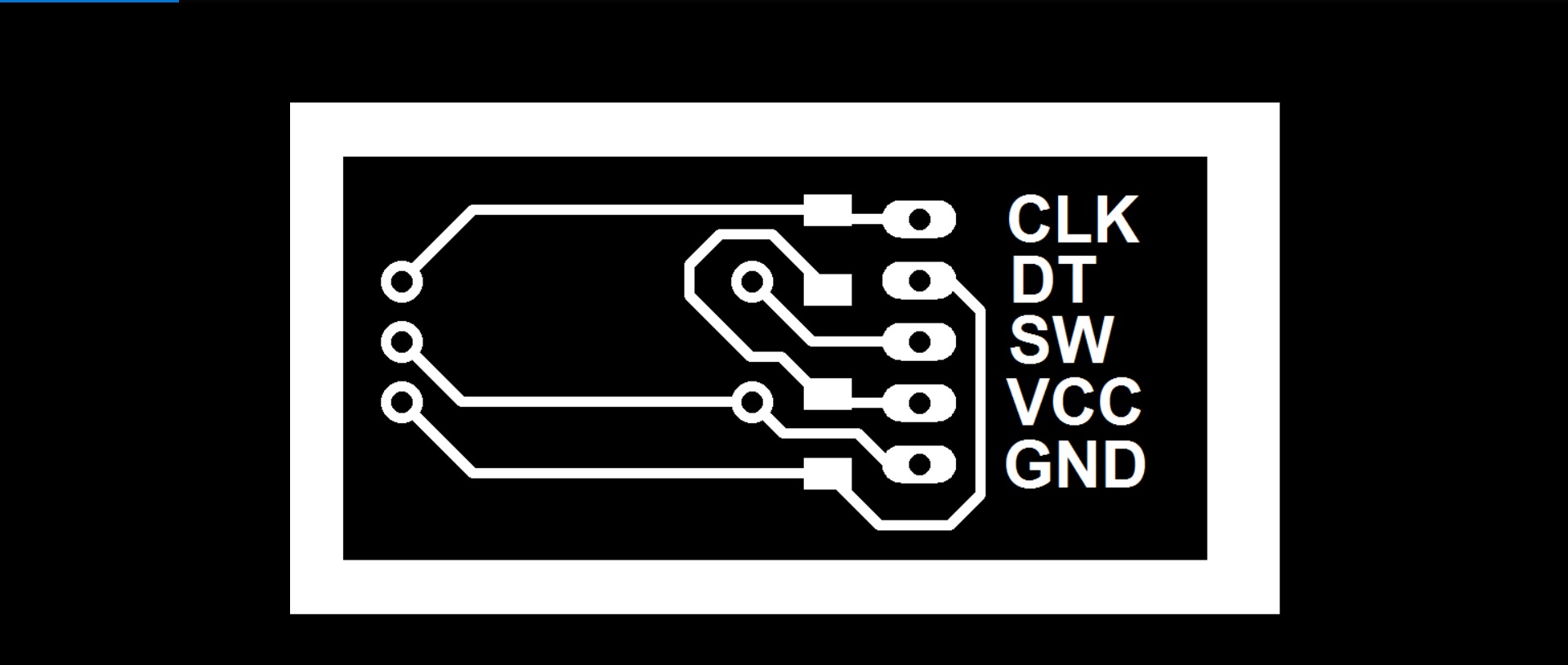
Finally the components are solved and it is ready for its programming, which will be programmed in Arduino for the final project.
CLICK HERE FOR DOWNLOAD THE BOARD ENCODER

Click here for watch the video
Improving my assignment.
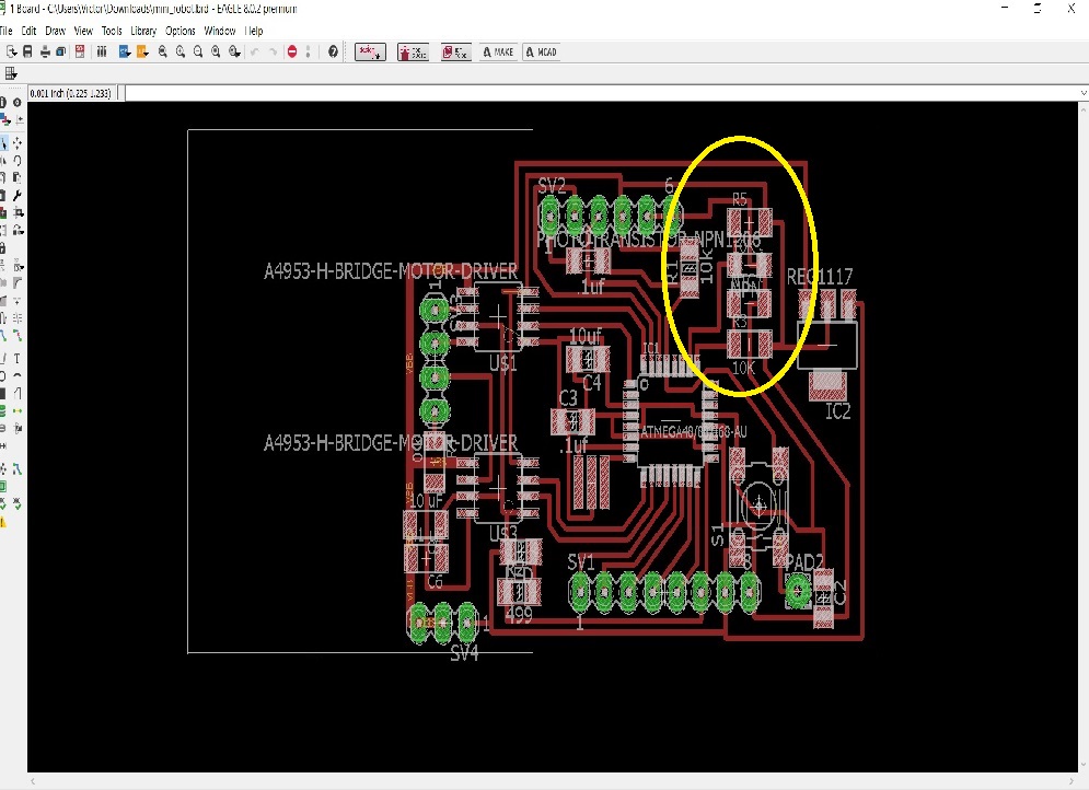
To improve my assignment, I manufacture a Board that has in its design a controller (ATMEGA) two Bridges H for DC motors, a Temperature sensor, and a Light sensor.
This board was designed in order to be able to use it as a mini robot that would have many functions.
The idea is to be able to use it as a roboto that is didactic for the user, so that the robot allows to move during the darkness and when the light comes on it stops.
Then to achieve these functions the plate will be divided into three parts:
- THE FIRST PART:
Embedded Programming (in this Assignment upload the files and showned the codes of programming of the controller, Budloader)
will be the manufacture of the plate in general and the programming of the controller as task of this assignment.
- The second part :Output Devices
will be the programming of the two H-bridge with DC motors, which will be Outputs, this will be documented in the week of the Output assignment.
-
THE THIRD PART :Input Devices
will be programming the THERMISTOR and PHOTRANSISTOR sensors as assignment task of INPUT. This will be documented in that week.
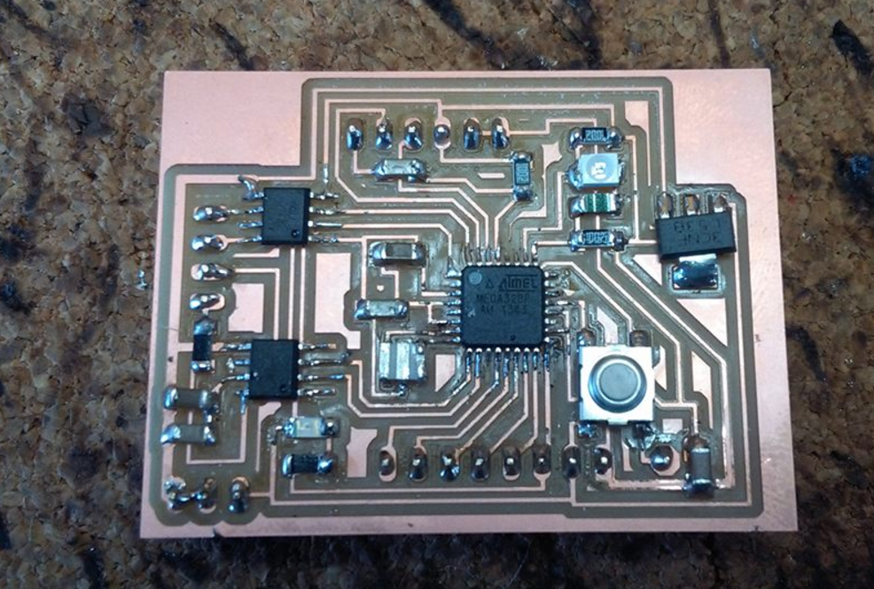
In this assignment, I use the Embedded Programming board which has the controlled ATMEGA328, two INPUTS (PHOTOTRANSISTOR AND THERMISTOR).
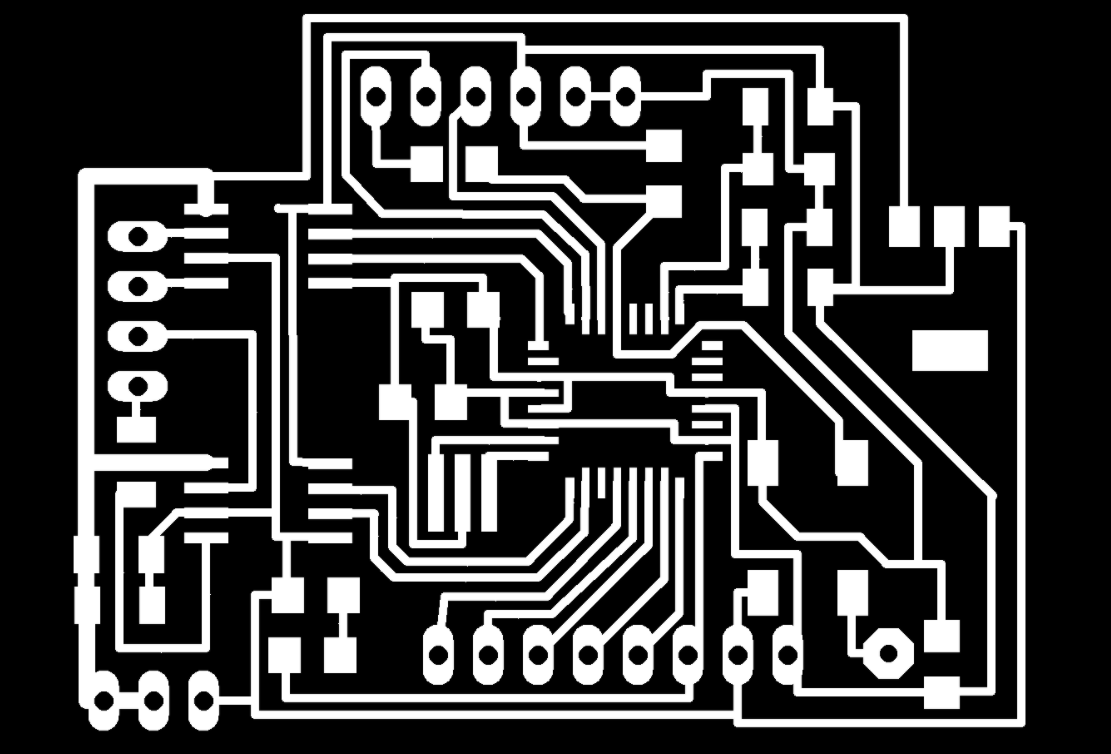

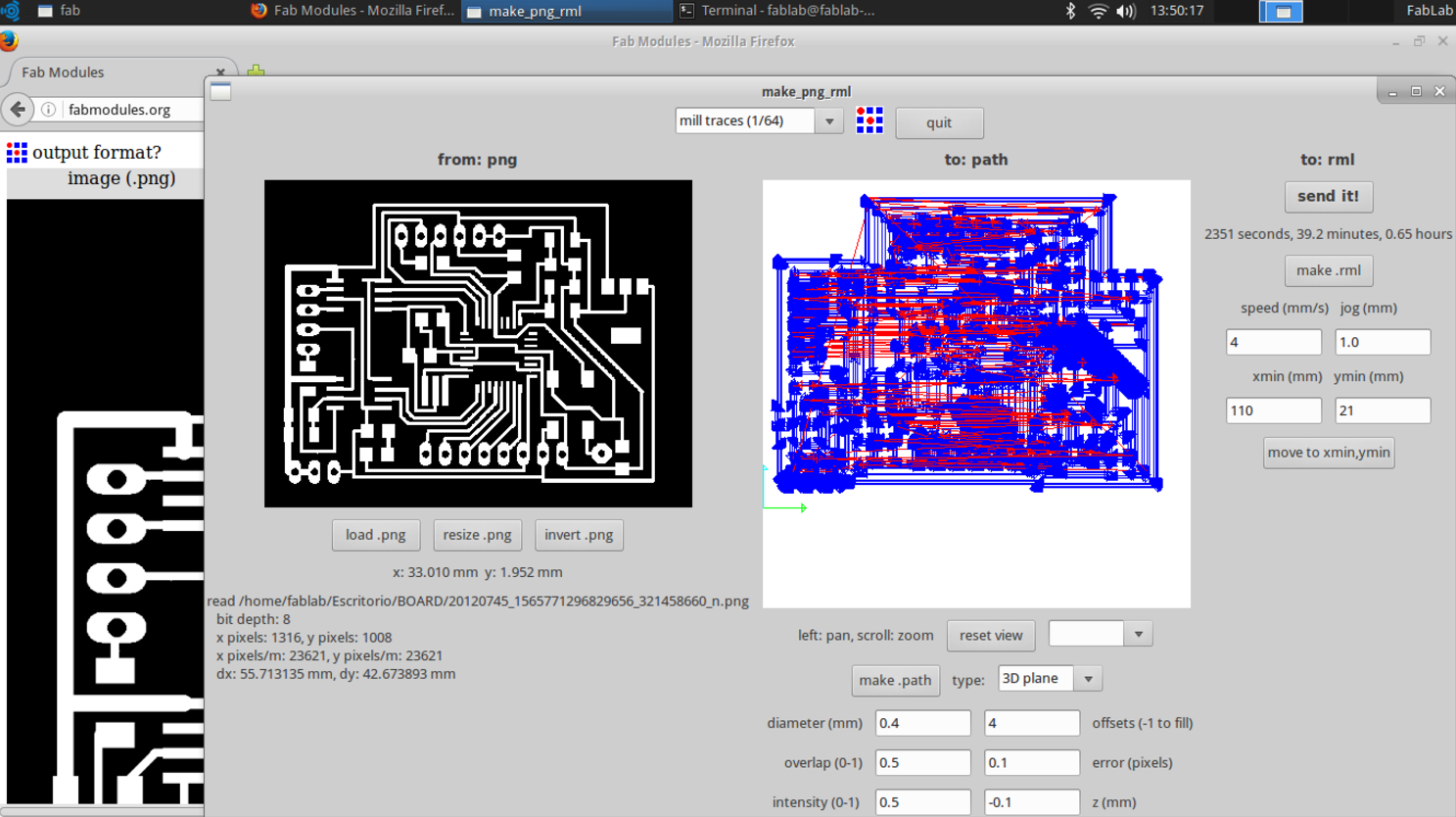
As previously mentioned, this board was designed and milled with the fabmodules.

As noted, this is the board, which has two INPUTS (phototransistor and thermistor) on the upper right side, which will be controlled through the ATMEGA328.
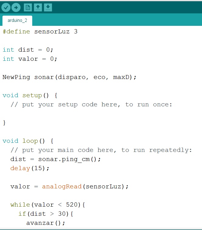
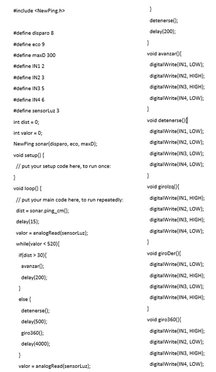
Finally, the BOARD is programmed in ARDUINO, for this it is indicated with the code that while the Photransistor detects a value less than 520 the programming done with the H-BRIDGES and motors DC must be executed, otherwise the motors stop, that is Because when the sensor detects a higher value to this is because there is light in contact and according to the didactic explained previously this must stop.
CLICK HERE FOR DOWNLOAD THE BOARD FILES
CLICK FOR DOWNLOAD THE ARDUINOS FILES