
Assignment 8
Embedded Programming
First, download from the schedule, the boards in EAGLE and the PNG files.
These are the schematic boards .


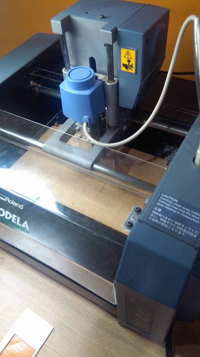
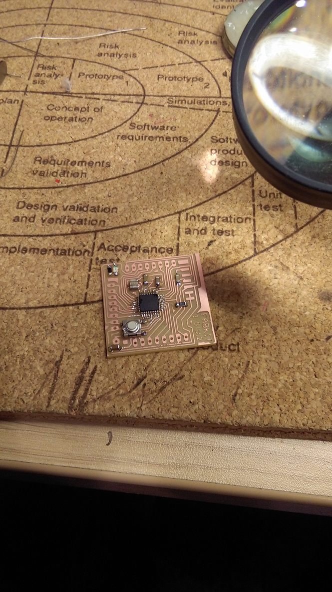
hen, use the MODELA to be able to mill my hello board.
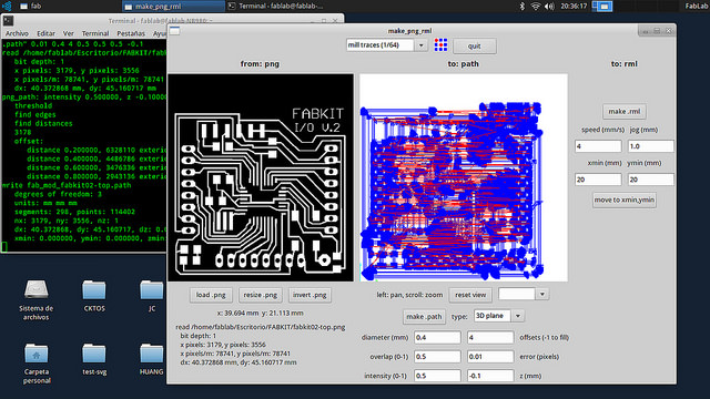
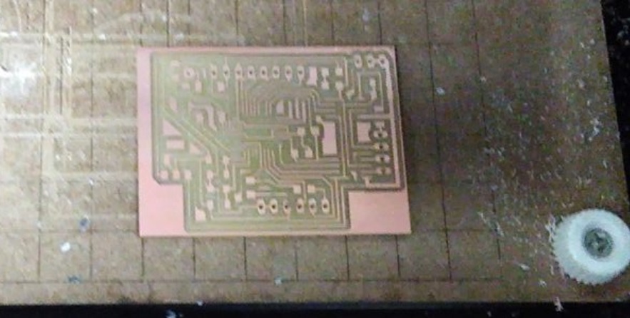
This is my hello board.

Click here for download the board files
![]()
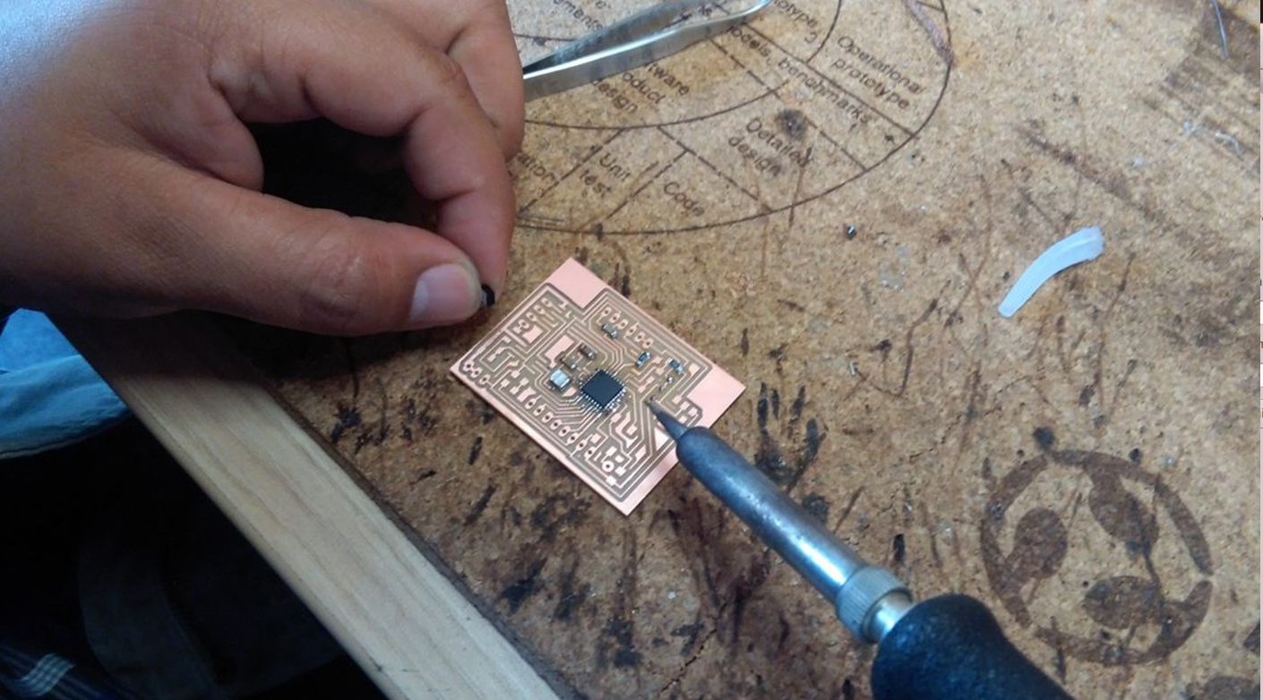
FOR THIS ASSIGNMENT I USED ATMEGA 328 MICROCONTROLLER
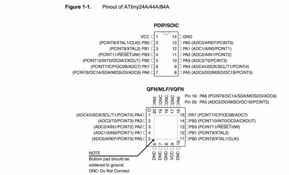
In this assignment I learned to use the data sheet of the electronic components that are involved in the BOARD, this document contains the technical specifications of the devices, in this case I use it to know the value of each pin of the ATMEGA 328, also being able to identify Which is a VCC and GND pin to avoid a short circuit. Know how to identify which are Digital or Analog Pines and their functions. And to be able to structure.
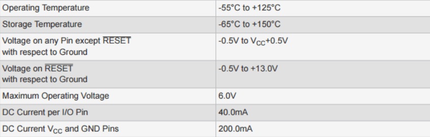
Electrical Characteristics
Before using any kind of chipset, we must read the electrical characteristics section on its datasheet, so that we can avoid that the chipset get burned accidentally.
Some basic parameters we must look for in a datasheet are the maximum and minimum power source voltage, the maximum curent that can be obtained from its output pins and the maximum current that the chipset can give summing the current from all its output pins. If one of this limits values is exceeded on the chipset, it will get burned
On the Atmega 328p this parameters are specified in Absolute Maximum Ratings and its corresponding values are 6 V ,40 mA and 200 mA respectively
Internal Components
The internal components of the chipset are usuallly specified on a section called "Block Diagram". The image below shows all the Atmega 328p internal components.
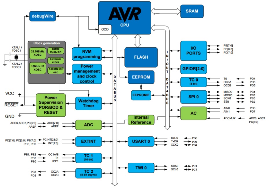
We can see from the image that this microcontroller has 3 main memories, which are the SRAM, the Flash and the EEPROM. The SRAM is the fastes of the three, thus it stores all the variables used in our
program in some of its 32x8 bit general purpouse registers; the flash memory, which is the second fastest, stores the line codes of the program and can be used to store not frequently used variables;
while the EEPROM, which has a limited number of writings, is used for storing constants that are not going to be changed almost never.
Comunication:
The Atmega 328p can communicate with other devices by serial communication (this means that the data is transmitted in a serial way by its comuncation interfaces). This Microontroller
has an internal USART, which is a piece of hardawre wich can comunicate by sending TTL signals, and it also counts with internal SPI and TWI modules which permit it
to comunicate in SPI and I2C protocol respectively.
CLICK HERE FOR LINK DATA SHEET ATMEGA
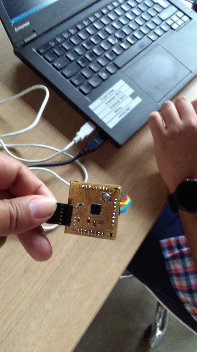
Then I solder the components that are needed according to the SCHEMATIC of the HELLO BOARD.
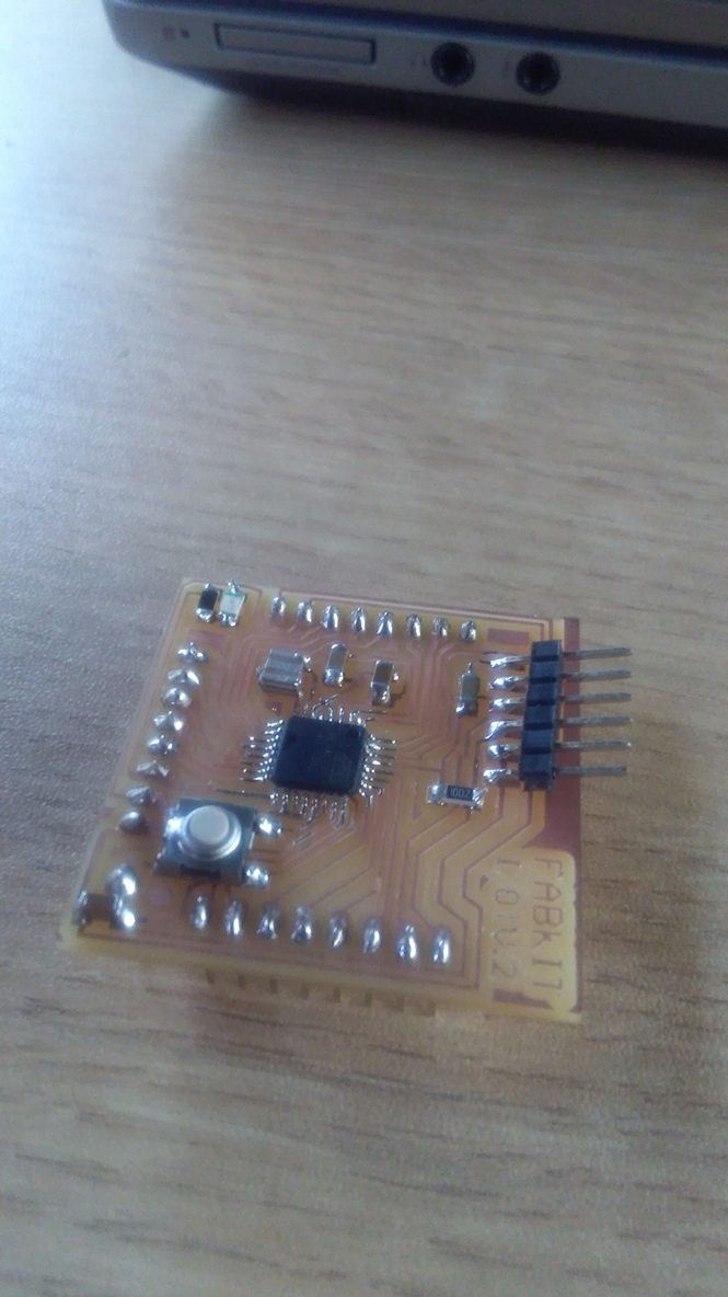
For the programming of my board I use ARDUINO software.

For this I use my ISP, a 3.3 V FTDI cable, and a USB cable.
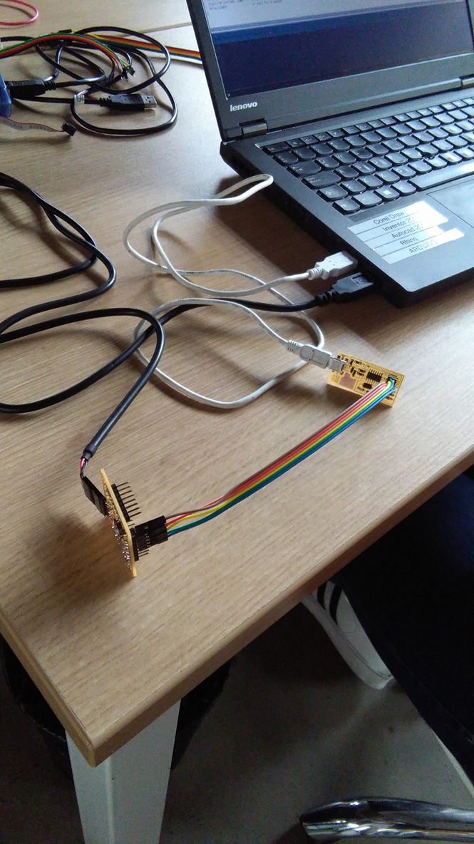
Now I will program my board with the ARDUINO program as the first Programming Language.
For this I only need a 3.3V FTDI cable.
I program that the led light comes on twice a certain time interval.
To do this enter the command DIGITALWRITE (13, HIGH) which mean that in the pin 13 where the LED is, send a high current and this causes the light to turn on.
Then the command DIGITALWRITE (13, LOW) , which means that a low current is sent, then the LED light is switched off.
And to be able to visualize that it is turned on and off twice, I set the time (DELAY) that has a unit of measure in milliseconds.
I enter 100 in DELAY of all the commands so that it is turned on and off in a constant time, but in the last DELAY I enter 10000, so that there is a longer interval between the second time the LED goes out and the start of the new one programming.
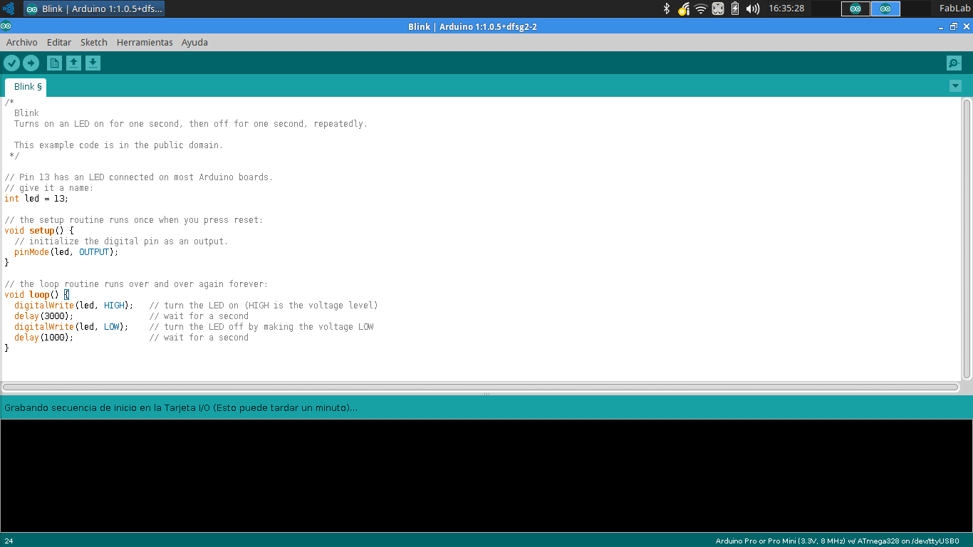
Then, we click on LOAD and wait for the program to load.

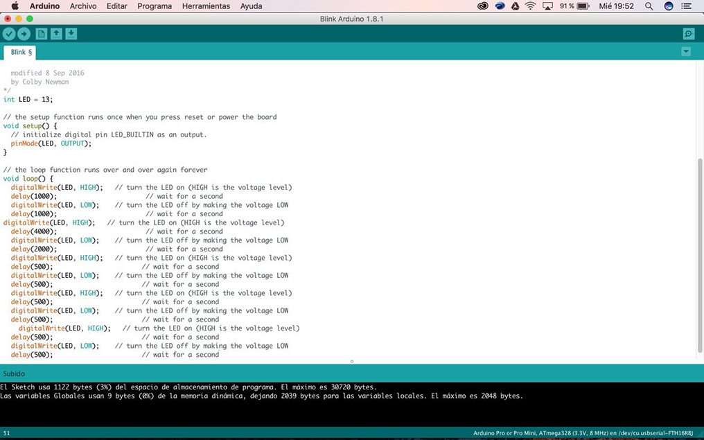
And as it is observed, the led light turns on twice for each time interval.

Click here for download the ARDUINO FILES
![]()
Improving my assignment.
To improve my assignment, I manufacture a Board that has in its design a controller (ATMEGA) two Bridges H for DC motors, a Temperature sensor, and a Light sensor.
This board was designed in order to be able to use it as a mini robot that would have many functions.
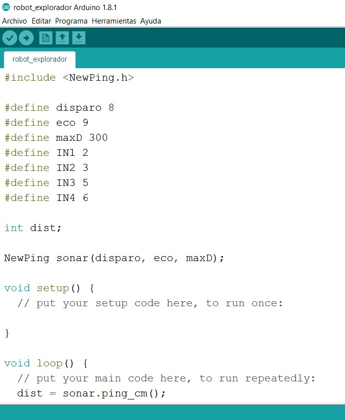
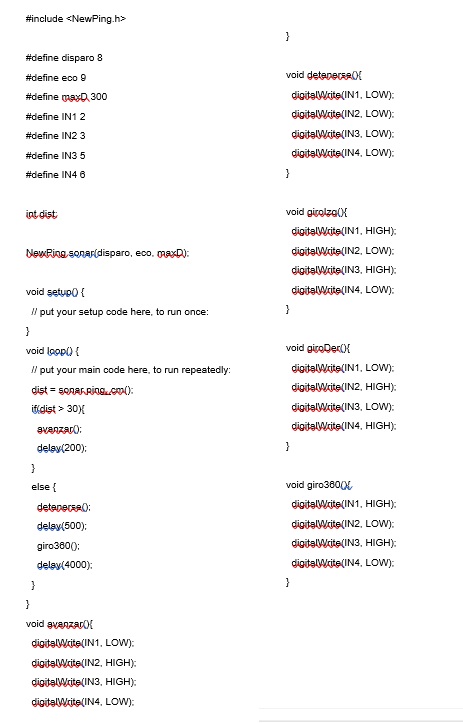
For this week, I did a simple code for a small robot that uses an ultrasound sensor and the bridges H to freely move around and evade obstacles. I like this robot because we use it to teach simple Arduino coding to students, but it ends with many wires because we use arduino+protoboards, so with my board it is much simpler.
I will test other codes using my new board for OUTPUT and INPUT assignments.
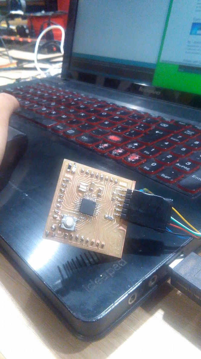
First, I design a board that has all the components indicated above, and a controlled ATMEGA328 which will be programmed in this assignment.

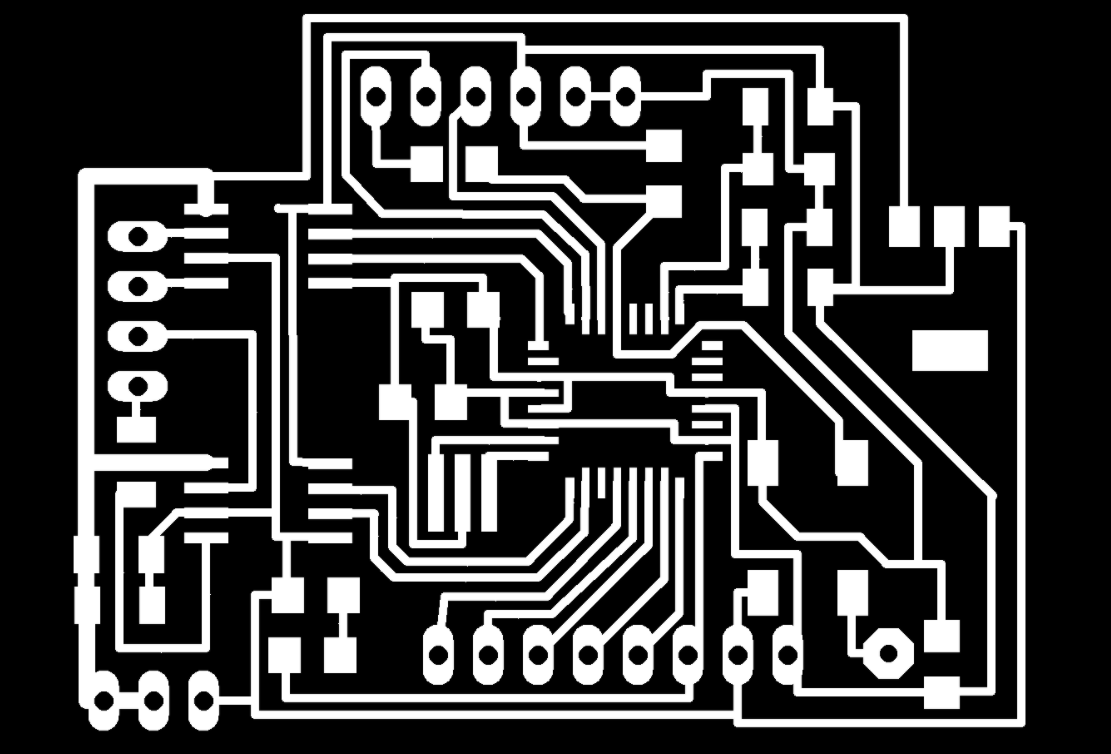
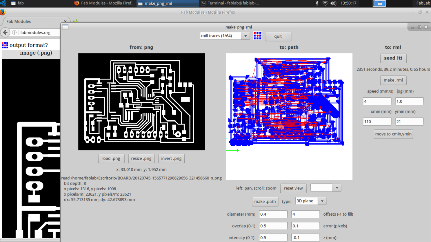
Then, I milling the board with the fabmodules, and solder the components.

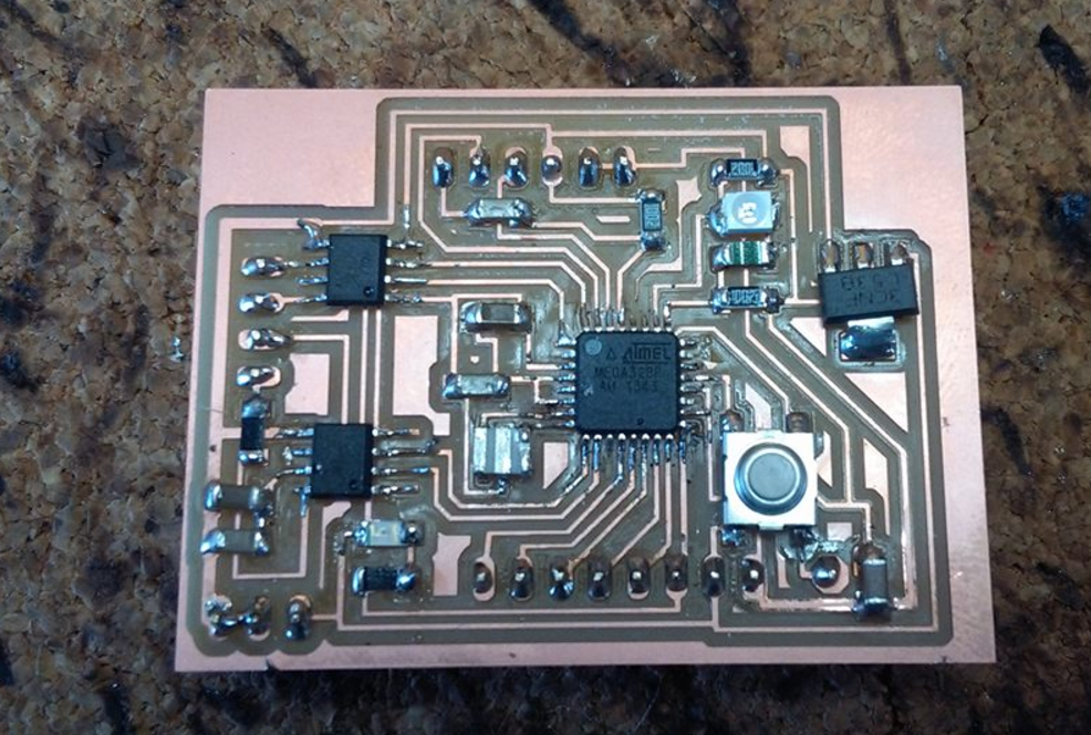
And this is the board, as you can see, the board has 2 H-BRIDGES for DC motors, a controlled ATMEGA328, a phototransistor sensor, a thermistor sensor and two additional pins to add some other INPUT DEVICES.
Programming with my ISP
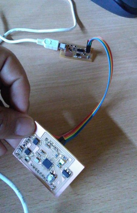
I upload the codes
Click here for DOWNLOAD THE BOARD FILES
CLICK FOR DOWNLOAD THE PROGRAMMING FILES