Greetings, here lies my work-log at
______    _      ___                _                             _____  _____  __   ______
|  ___|  | |    / _ \              | |                           / __  \|  _  |/  | |___  /
| |_ __ _| |__ / /_\ \ ___ __ _  __| | ___ _ __ ___  _   _       `' / /'| |/' |`| |    / /
|  _/ _` | '_ \|  _  |/ __/ _` |/ _` |/ _ \ '_ ` _ \| | | |        / /  |  /| | | |   / /
| || (_| | |_) | | | | (_| (_| | (_| |  __/ | | | | | |_| |      ./ /___\ |_/ /_| |_./ /
\_| \__,_|_.__/\_| |_/\___\__,_|\__,_|\___|_| |_| |_|\__, |      \_____/ \___/ \___/\_/
                                                        |_|
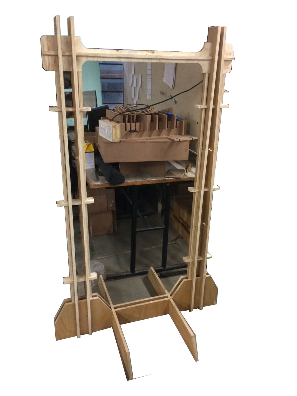
I wanted to do several things for this week including a framework for a practice drumkit, several exercise equipment like the olympics gymnasium rings, a pull-up stand or dips stand or a multi-gym (>.>) . I was getting ahead of myself quite often. I ended up making a pull-up stand for kids :/ OR a cloth hanger(the thing all home-bound exercise equpment end-up being eventually. ) or a hanging display framework, whatever be it called; I made something bigger than myself. B)
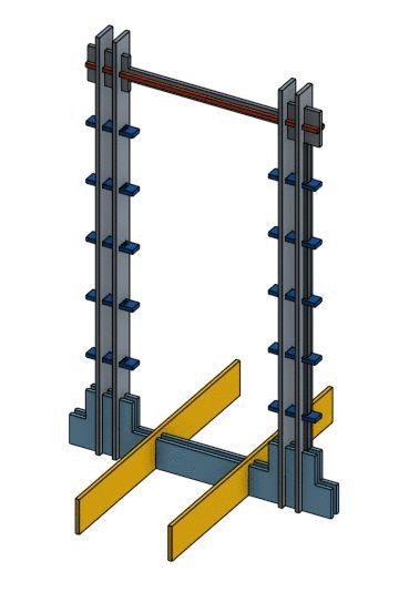
the above image is the design i modelled in Onshape, it has a nice pricing model ( free for hobbysits who open-source their designs )
Sketching in OnShape is based on constraints and relative relationships between geometry; the more constraints set on the geometry, the more defined it is said to be.
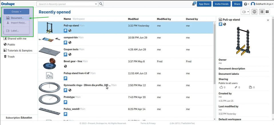
Step 1 : Sign up on Onshape.com for an education plan or the Free plan for public designs, and from the home-page go to -Create >> Document
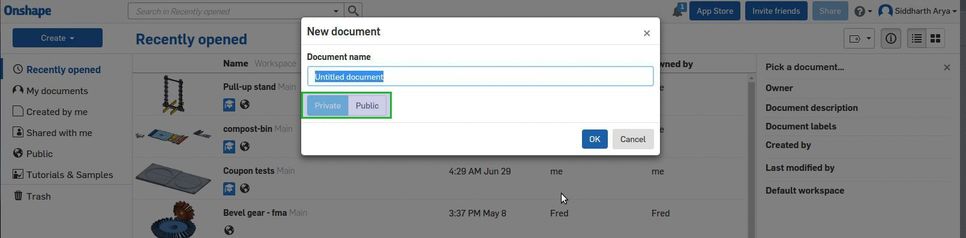
Step 2 : Name the document and select 'public' document.
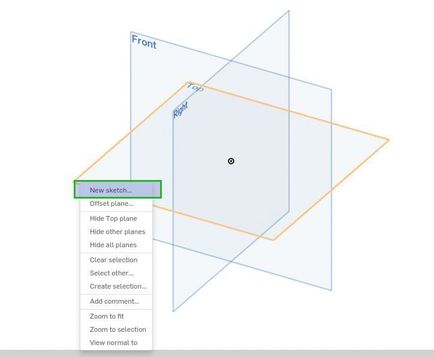
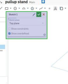
Step 3 : Right-click in the model space and select 'new sketch' and select the plane on which the sketch will be drawn on.
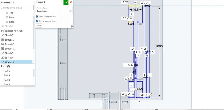
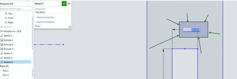
Step 4 : Check 'show constraints' to see constraint icons and relationships(parallel / perpendicular / equal ) between entities like lines and points
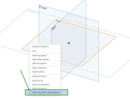
Step 5 : Right-click on the model space, and click on 'view normal to sketch space'
To create planar geometry, these are the tools available - most of them were familiar to me as they are similar to other CAD tools

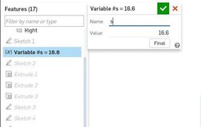
this feature right here - 'VARIABLE' blew my tiny little drafting mind. It's a definable variable which can be used to dimension geometry which can be later 'varied'. Parametric stuff - yeah. I used it to define all the dimensions pertaining to the slot widths which depends on the material thickness which was going to change after I determine the tolerance adjustment from the test cut. I defined 's' as a variable and 's' was initially defined as 16.7 mm, to dimension a line as equal to 's', one has to reference it by typing '#s' in the dimension box
All the little icons are indicating constraints and relationships amongst geometrical entities
So, I finished all the profiles of the parts in sketches
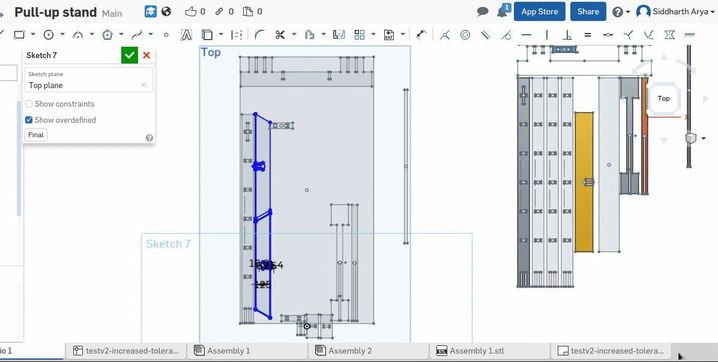
Here it is again. The variable feature. It saved a lot of time
In a product design workflow like OnShape's - you make parts in part studio through sketches and modelling and then assemble the parts and define the relationships between them in a new enviornment called 'Assembly'
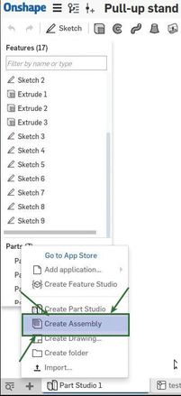
To start an Assembly, select 'New Assembly'
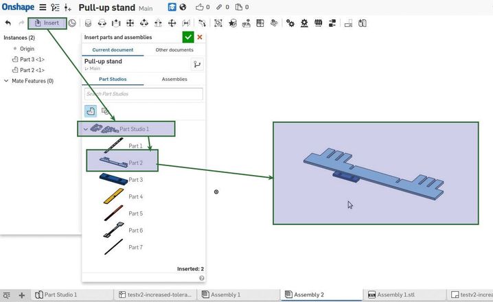
Import all the parts
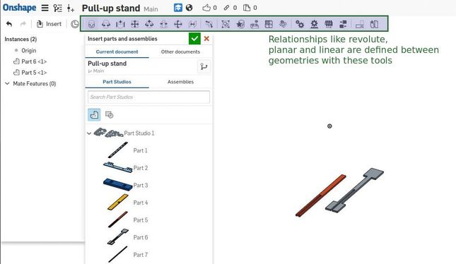
Select 'Fastened mate' to join the parts
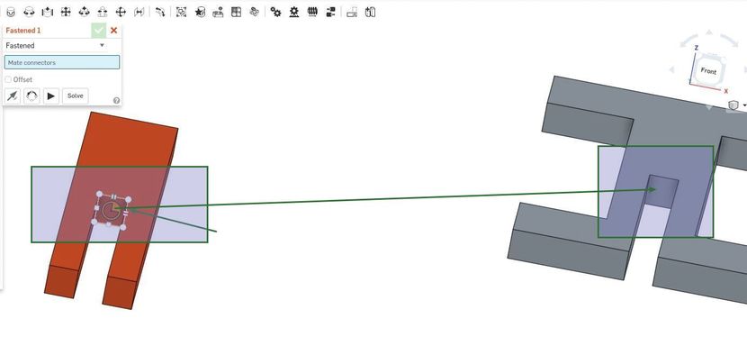
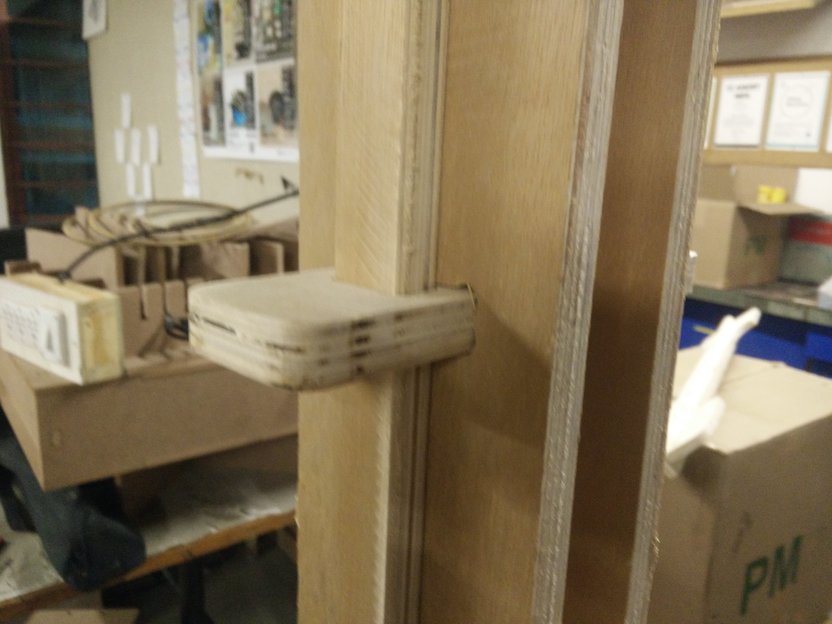
Two interlocking parts
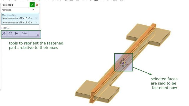
Forming the handle of my pull-up stand
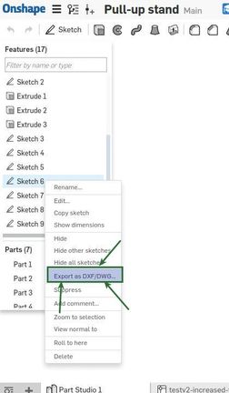
Exporting in OnShape is quite straightforward - we need DXF formats to open in PartWorks
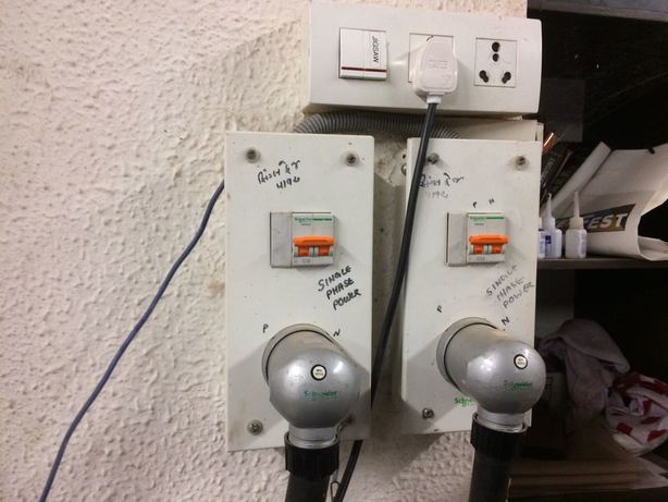
The shopbot requires 2 power feeds - A 220V power source that powers the control box and the 220V power source that powers the VFD (Variable Frequency Display (display???)), that controls the speed of the spindle.
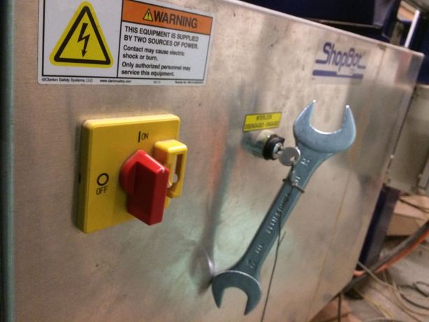
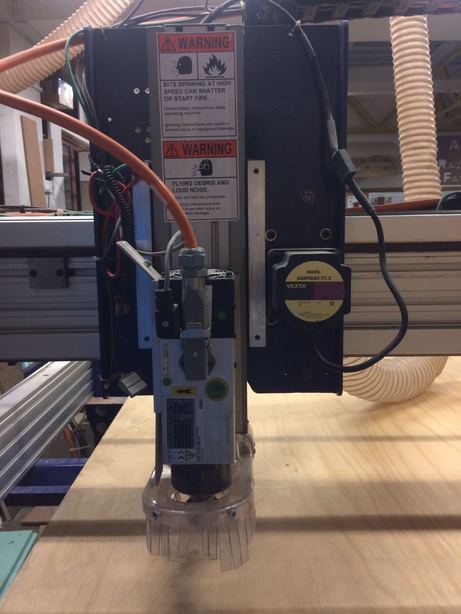
This is the main power-on&off switch, the key engages or disengages the power to the spindle
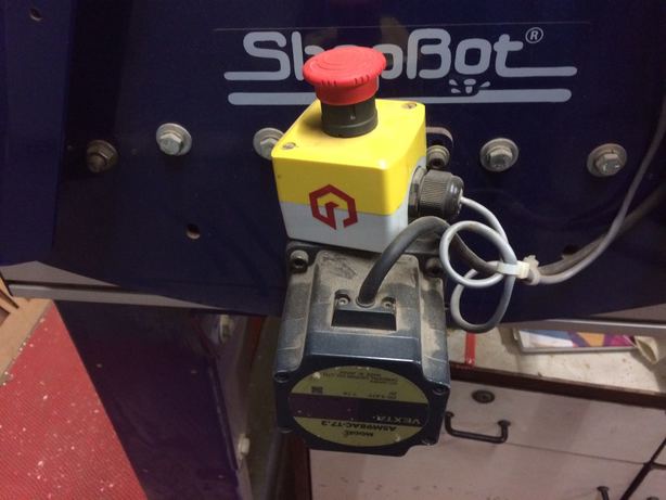
This is the aptly designed emergency stop button, which if used has to be uncocked before using the machine again.
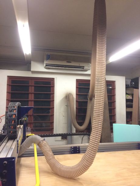
This is the exhaust system which collects the milled sawdust/scrap, dust from MDF is considered harmful - so an efficiently running exhaust system and a mask would be prudent.
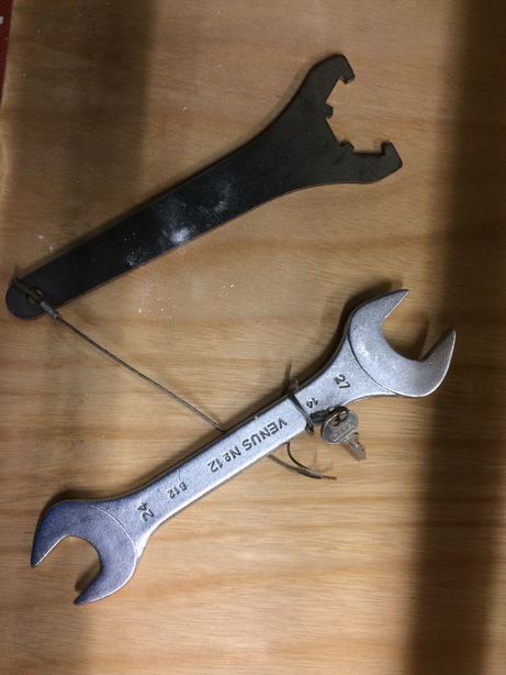
This is the spanner and complimentary 'lock'er (don't know what it's called) to open the collette/milling bit assembly.
The next thing I did was to move the gantry/spindle/milling head to the origin
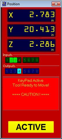
This is the software workflow to move the origin, it starts by this dailog of the control box
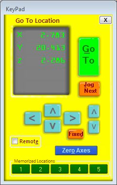
And then the 'move' dialog, with corresponding arrow buttons for each direction.
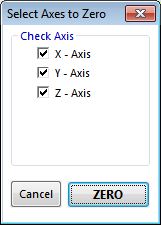
When the bit is at the right position in space, you zero all the axes to set the origin
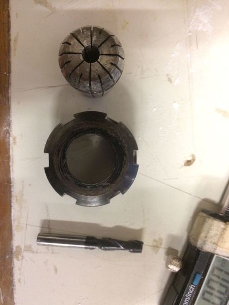
These are collette, chuck and a 1/4th inch up-cut 2-flute milling bit
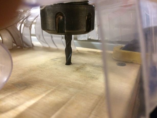
the assembly in position
Up-cut and Down-cut are types of spiral milling bits; up-cut bits scoops the chips upwards .
Climb and conventional cutting dictates the direction of movement of the bit - in conventional - the cutting edge bites into the material and in climb the bit shaves away at the material .
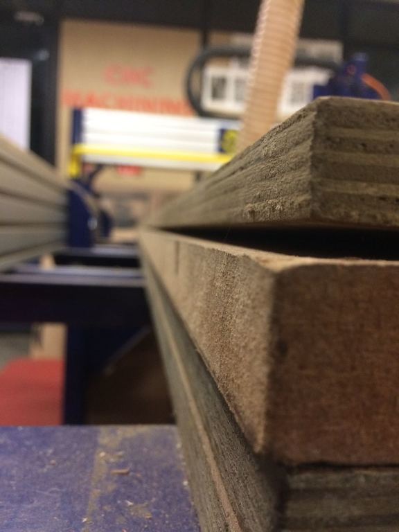
FIxturing is the process of affixing the stock to the bed of the ShopBot, here you see in this glorious smartphone photography that my plywood is bent and needs robust fixturing for uniform milling
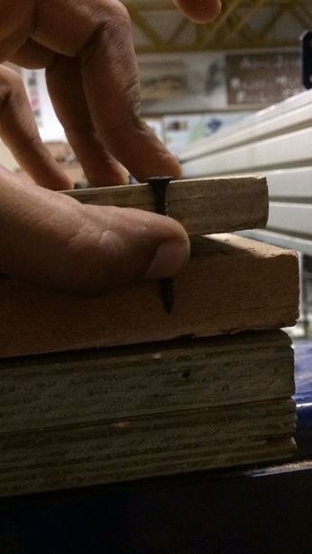
A nail wouldn't suffice
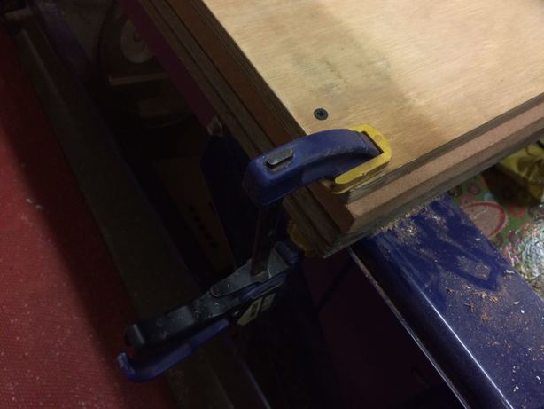
So, a clamp is needed as well
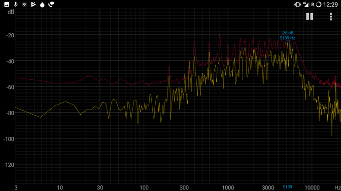
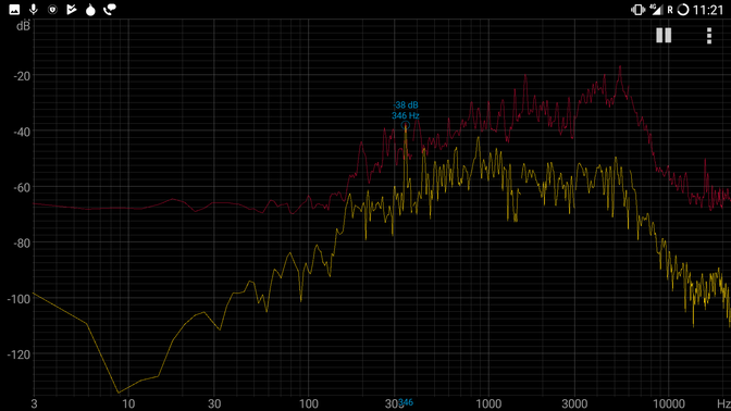
In this video below, I make the CNC mill 3 profiles at 3 different feedrates to determine the optimal feedrate - I tested 1.5 to 2.5 inch/sec feedrates at the maximum spindle rate and determined that at 2 inch/sec the milling sounded the most like it was growling and not screaming
Frequency recordings at optimal CNC milling sounds, *sob* when the beast growls.
the test profiles I cut
Starting at 1.5 inch/sec
Another profile at 2 inch/sec
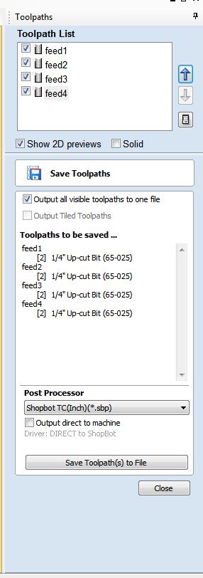
Then saved all the toolpaths as a single toolpath
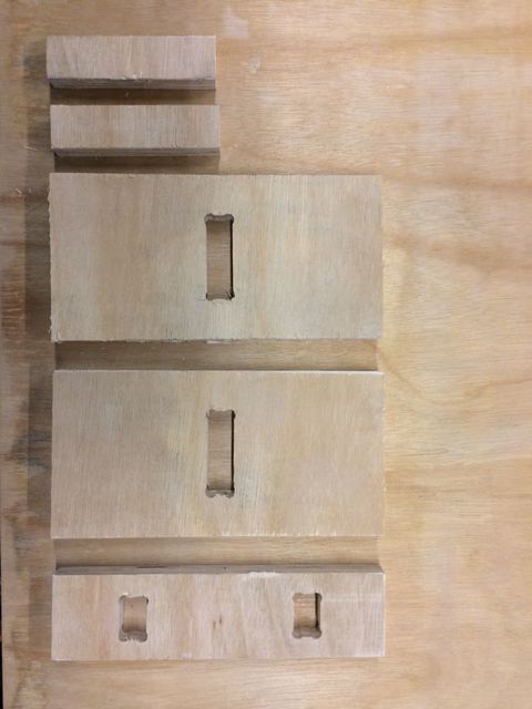
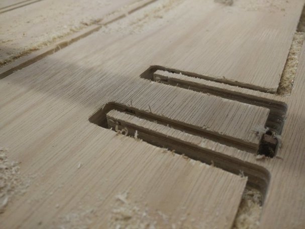
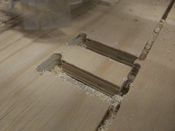
I milled a small test assembly to test the joinary
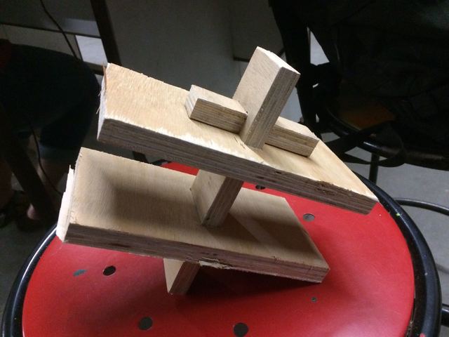
It fit quite snugly, the tolerance i had to account for was about +0.7mm
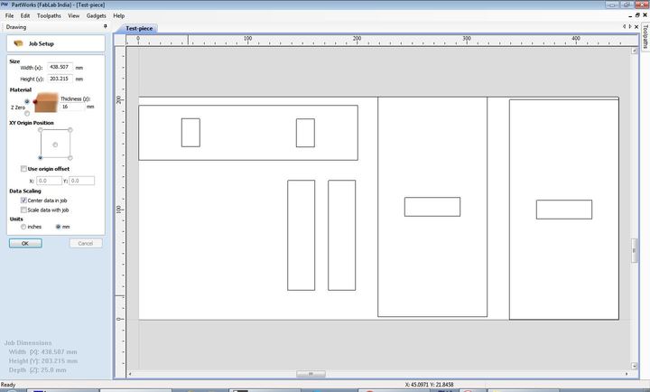
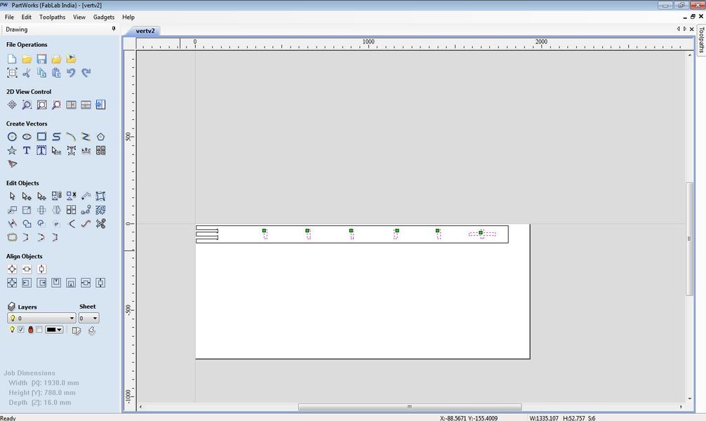
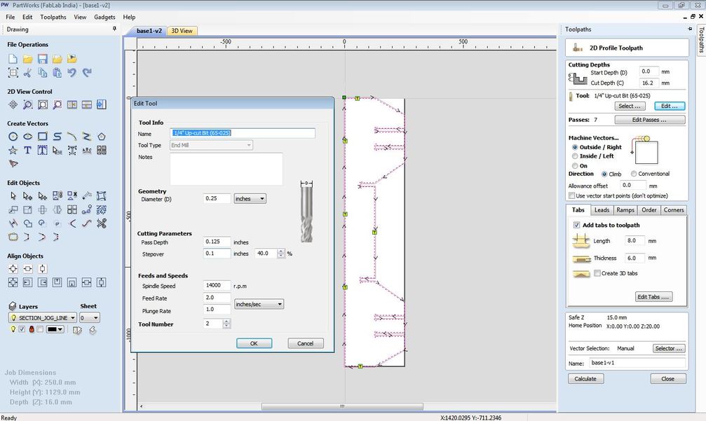
Workflow to create the toolpath in 'Partworks' is as follows - here are the profiles of the cuts to be made for the test piece
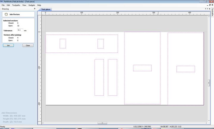
I'm making sure all the profiles are joined loops with the 'join open vector loops' tool
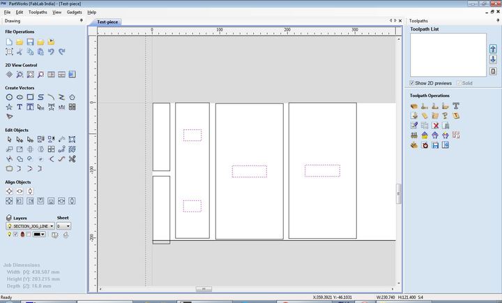
here I'm selecting the profiles that need the milling to happen inside the profiles - the slots
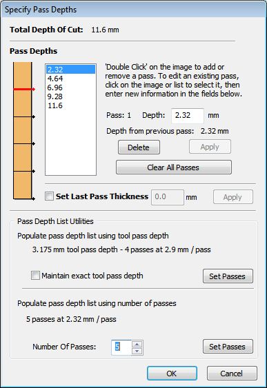
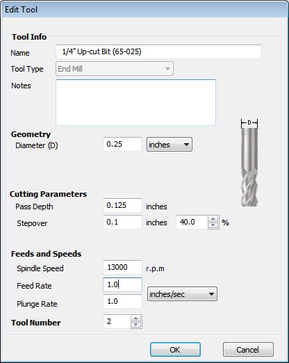
Pass depth is the depth at which the milling bit will go to during each pass
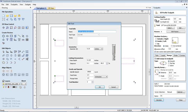
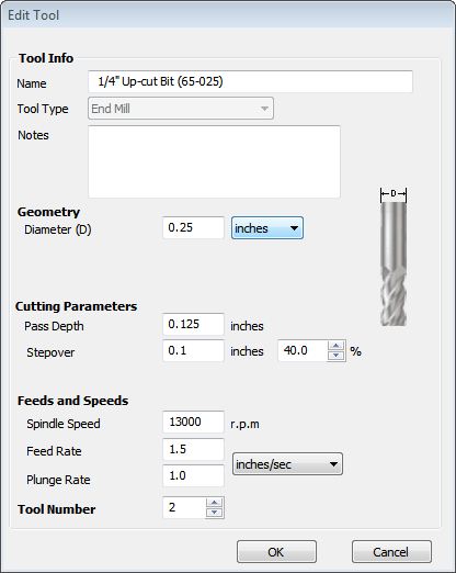
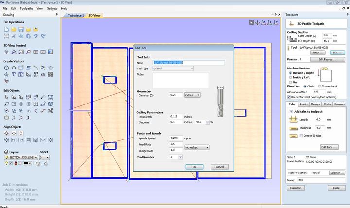
Here I'm specifying the 'feedrate' , 'spindle speed' , 'plungerate' - values for which were determined by testing the bit I was using against the stock I had
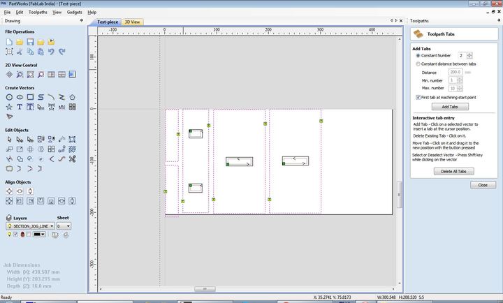
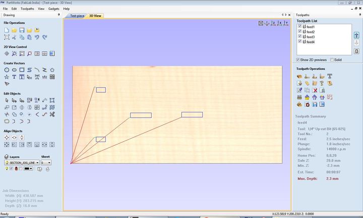
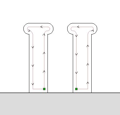
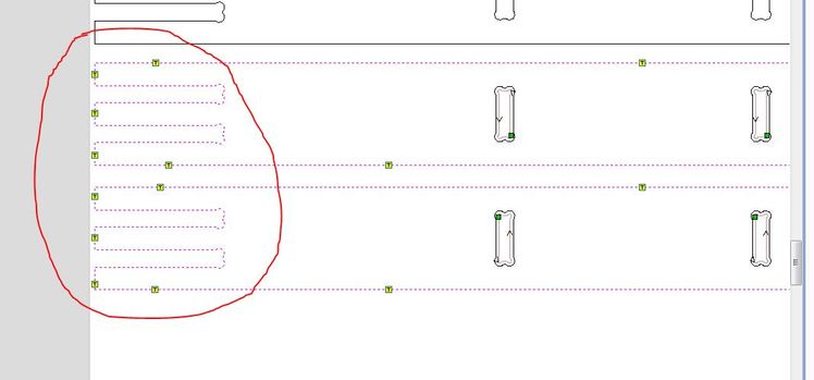
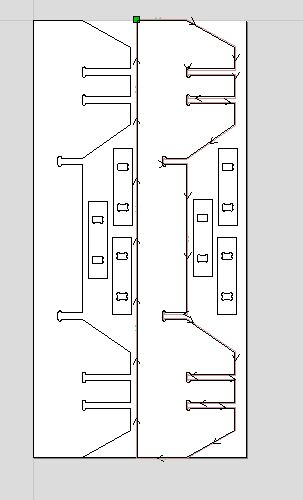
the toolpaths generated here are previewable under the 3d view tab, the 'T' icons are Tabs that I've placed for the exterior profile cuts
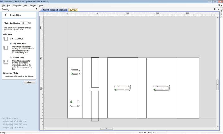
Partworks also has a tool to add 'dogbones' to corners - ' Dogbones' are provisions to overcome the inability of a circular sectioned milling bit to mill a sharp corner
the 3D view tab with the 'jog' paths shown in red lines
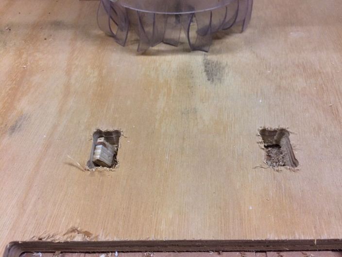
the material thickness of my supposed 16mm thick plywood varied as much as +2mm at certain places, resulting in incomplete cuts at a few places. I resolved this problem by cutting certain profiles with a deeper depth(?).
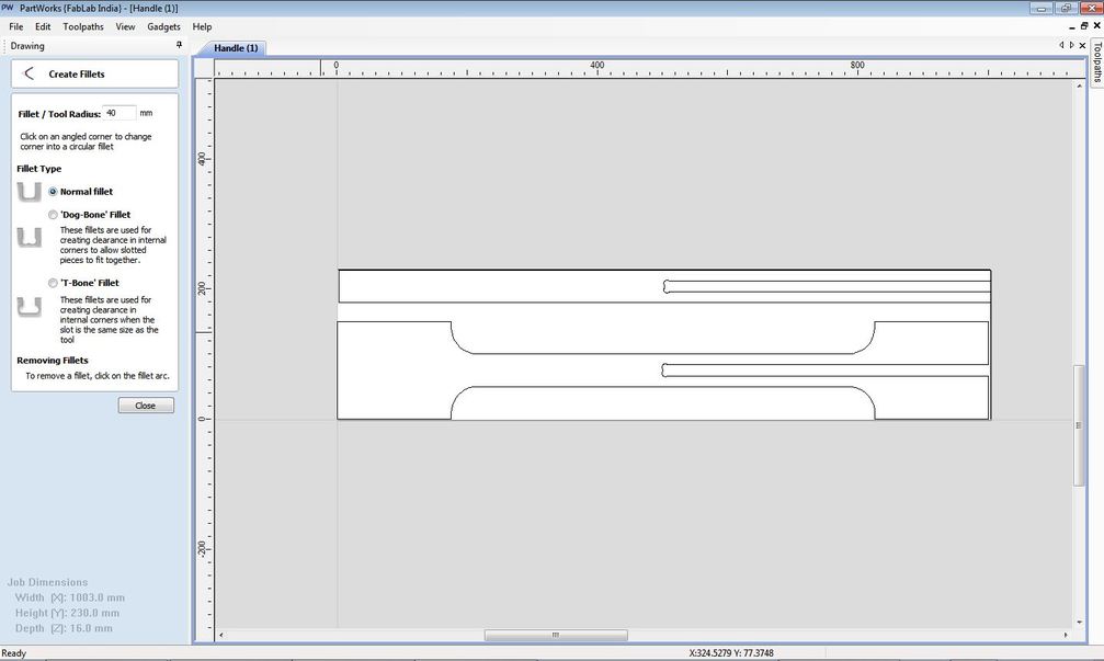
I forgot to add dogbones to a profile
profile without dogbone
toolpath to correct the profile
profile after cutting the dogbone profile with the same origin . Good 'repeatability'
Another crucial point to note is that ShopBot has an open-source language based on g-code known as the OpenSbp language which has the format .sbp.
If you generate g-code in the CAM workflow you are used to; shopbot provides a g-code to sbp converter.
imPORT the profile
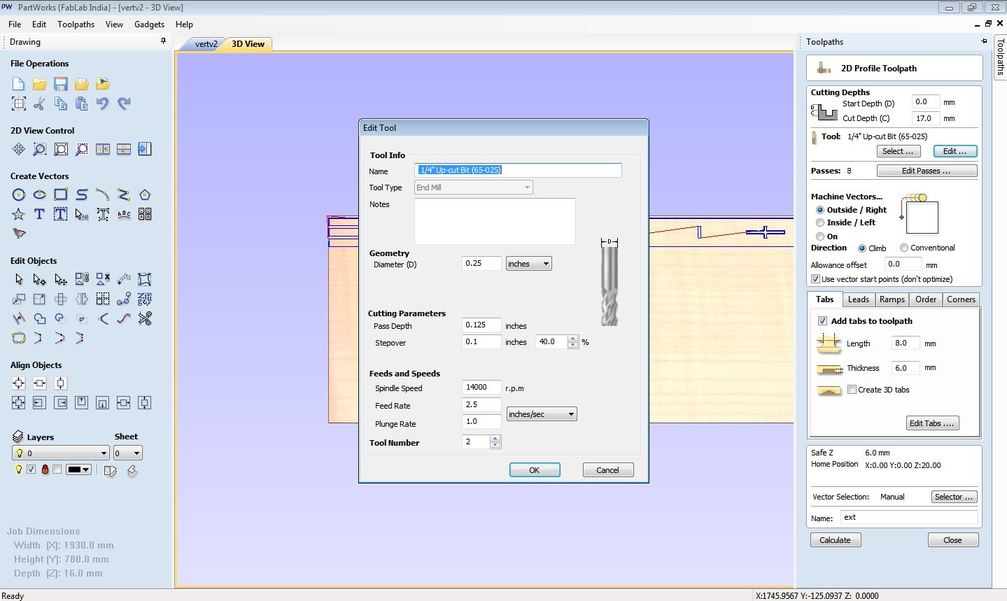
Select the bit, specify feedrate and spindlr speed
Pay attention to where more tabs might be required because of slender bits which might rattle or break off
More profiles
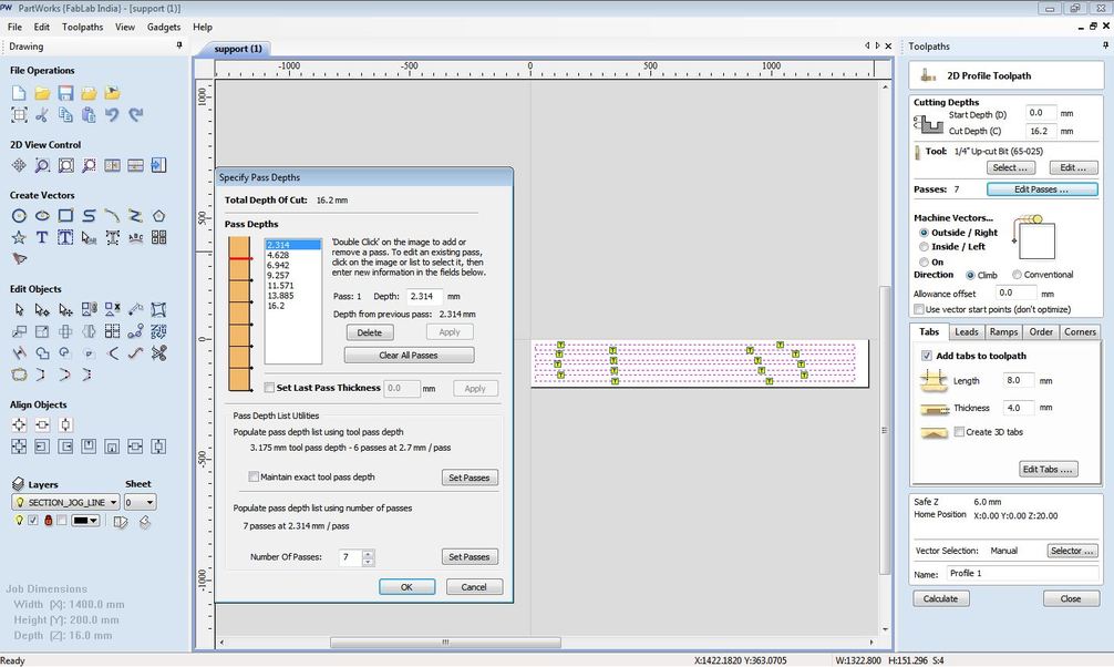
Setting pass depth
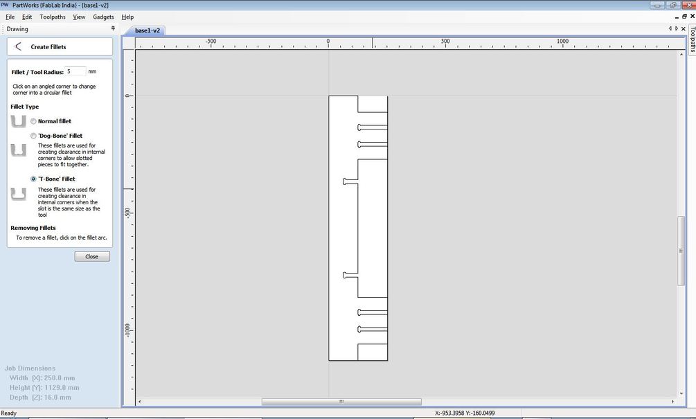
Partworks also has decent tools for vector manipulation, I changed my design a bit in Partworks
the changed bit, I added chamfers instead of straight cuts at the base
Arranging profiles is a breeze too in PartWorks
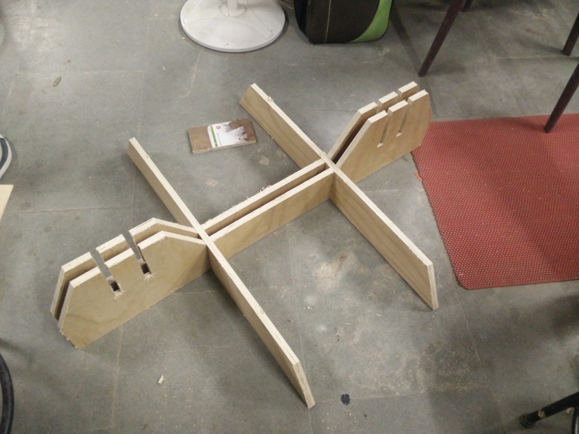
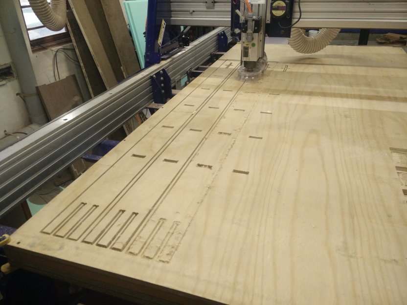
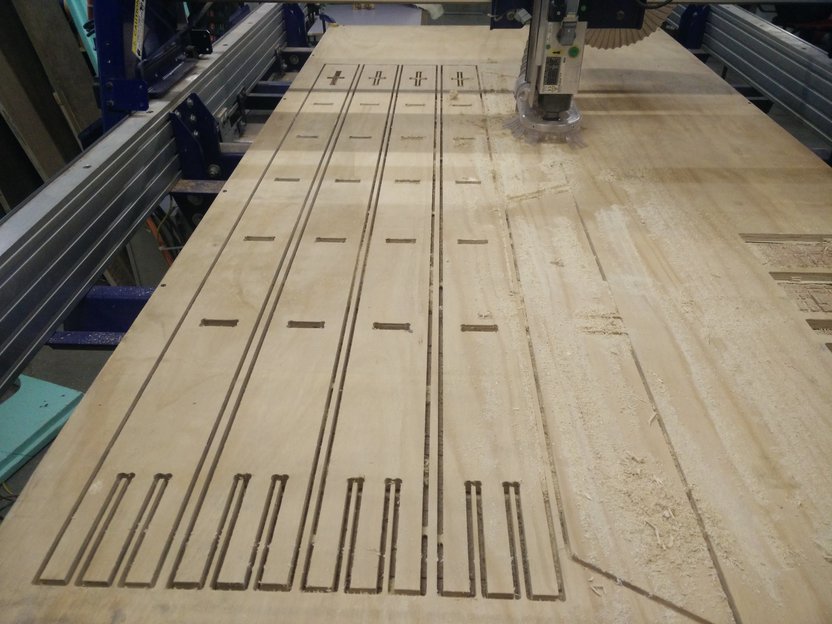
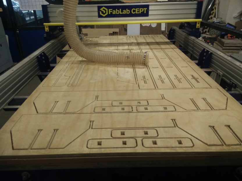
Progress pictures of the milling, one sheet turned out to be enough for my design
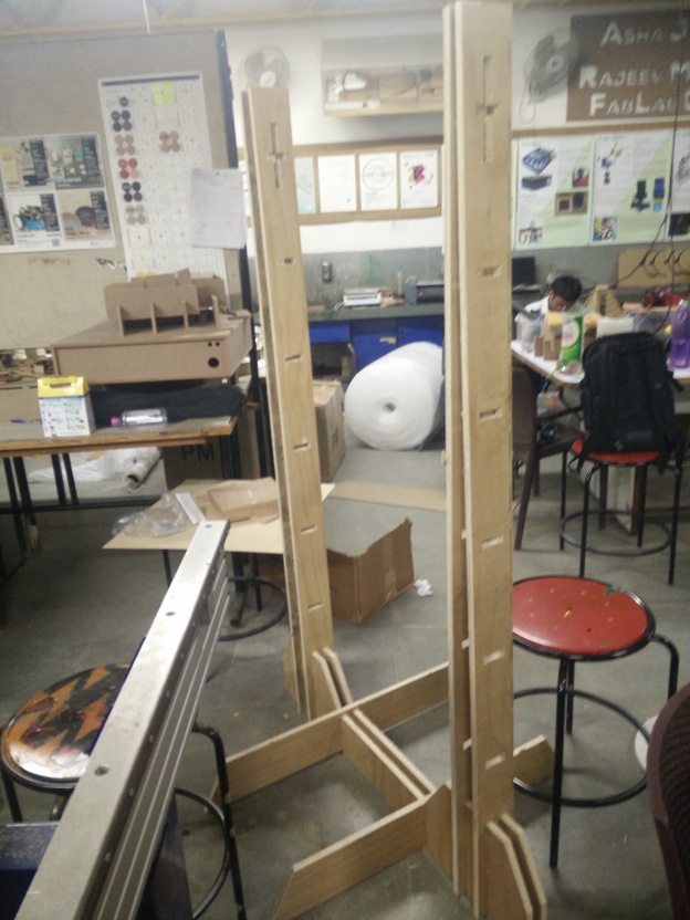
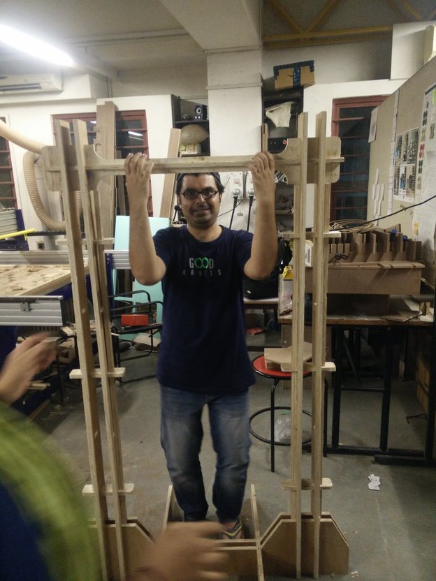
Progressive pictures of the assembly, ending with the Hero-Shot