Explained how you made your files for machining (2D or 3D).
Shown how you made something BIG (setting up the machine, using fixings, testing joints, adjusting feeds and speeds, depth of cut etc).
Described problems and how you fixed them.
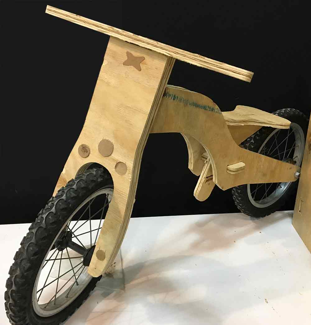
Included your design files and 'hero shot' photos of final object.
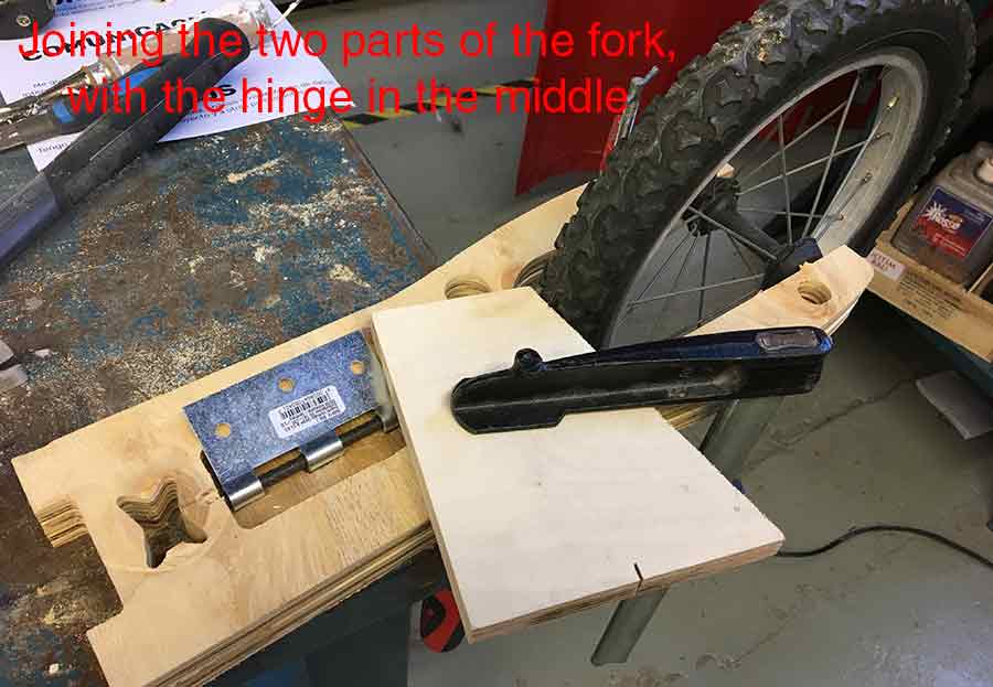
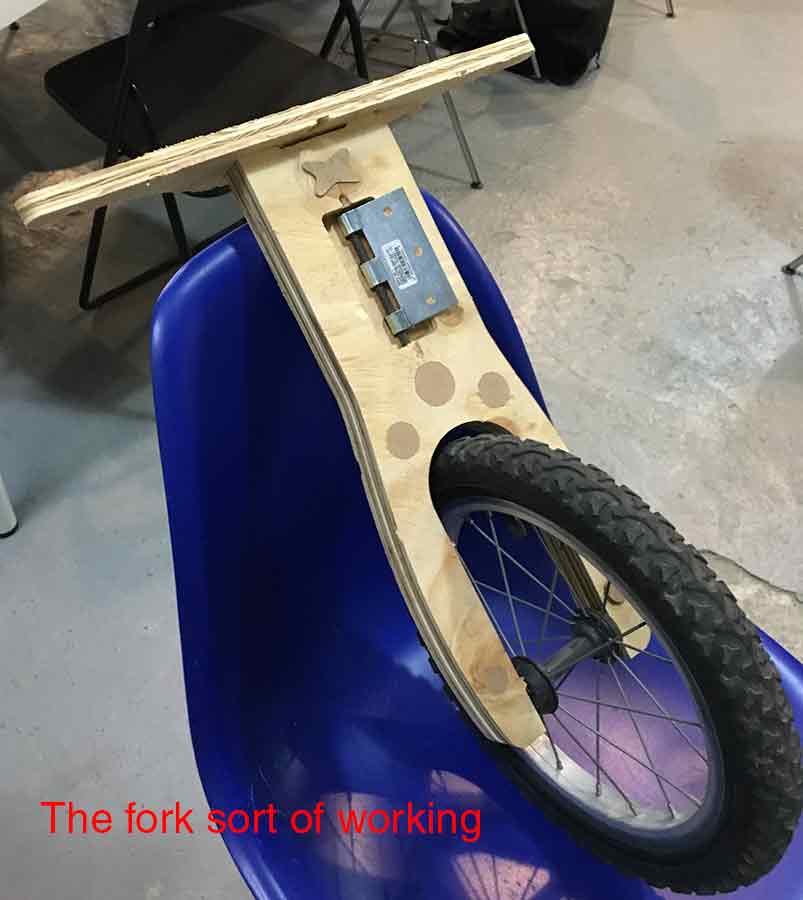
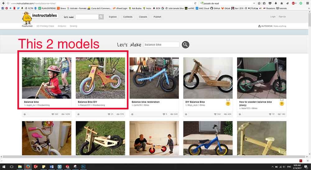
This week's assignment was to make "something big" using a milling machine and designing the joints to be pressfit. I have been wanting to build a balance bike for my niece for a while now. She is turning two in a couple of weeks so I thought this was the perfect occasion. I did a little research and find the model I wanted to build on google without any trouble. I even found two Instructables projects on it. Both used different techniques for joining the frame to the fork. I read them thoughtfully and decided to use a hinge to do this joint, like the second version. I liked the look of the bike better, when the front part is made from one whole part. I also considered that adding an extra layer of ply to the fork would make a better structure. After having decided which model I was going to do, I started considering how I could do something like this including the pressfit concepts.
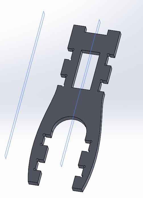
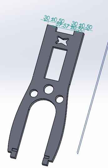
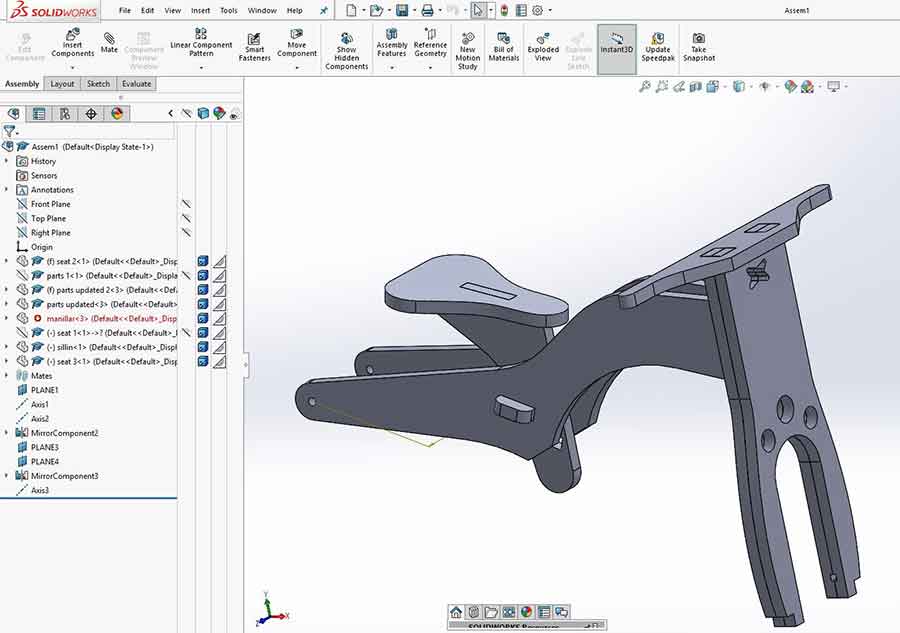
The first step was to design the pieces and try a couple of approaches. I have used Solid Works for the design of the pieces, which also allowed me to check the assembly of them. I decided that I was going to use pressure joints to keep both fork parts together, also the handlebar would do the trick on the top part. My first option used pressure parts on the sides, but after talking with our instructor Santi a little bit, we realized I was losing a face to generate total friction, so I move the friction elements to the inside. At first I just put a couple of squares with circles on the corners, but after having a class on CNC design and rhino cam, I realized I could design this a little bit more, as they were going to be seen on the front of the bike. I did some circles and an X instead. The rest of the joints were regular pressfit and the wheels were going to be fastened with nuts and screws.
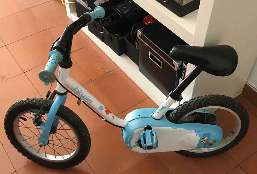
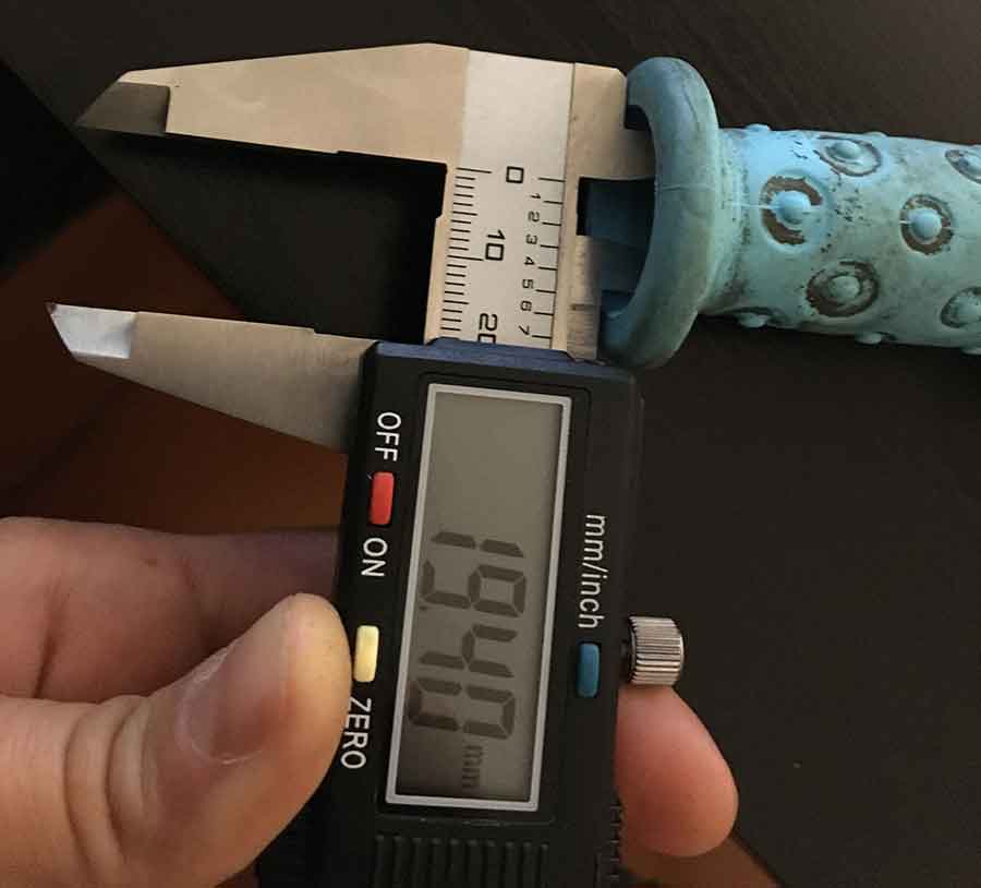
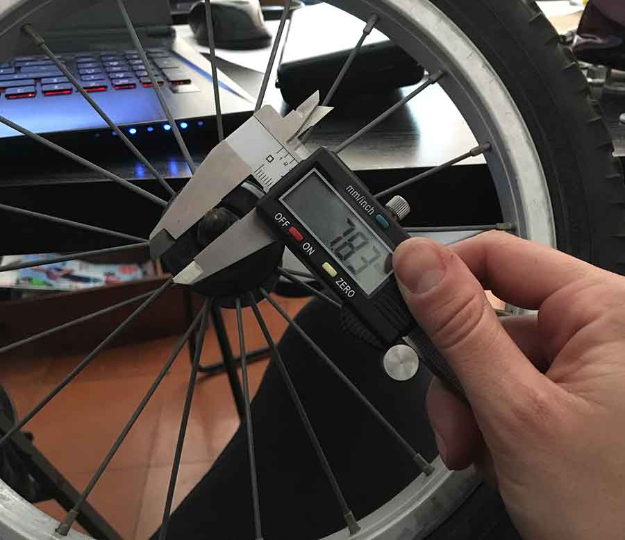
For the wheels, as time was an issue, I bought a crappie second hand kid's bike for under 10 euros and dissembled it. I also got the rubber handle covers and the wheels. With this I could model the few details left, as the engraving on the fork for the wheel axis, and I did the dimensions out of the real seat too.
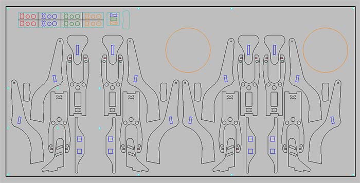
For the cam, here at the lab we use Rhino-Cam, it is a Rhinoceros plug-in with a lot of control over the milling process. The first step was to import all the pieces into Rhino. To do this I saved as .dxf on solid works, and opened the on a new Rhino layout. I created a 122x235 cm rectangle as this was the dimensions of our material. The first step was to do the nesting of our model. This is an important process as we want to optimize the material as much as we can. For my first prototype, I was going to use only one fourth of my stock, so optimizing was not my biggest problem. Actually if I wanted an optimization board I could mill 4 bikes!
Once all the pieces were laid on the sheet of material it was time to think on the strategies. Also, as my joints were pure friction joints I had to do a test before knowing the right tolerances for my gaps. I needed a 30 mm thick material, the only scrap one I could find was MDF, I didn't think it could be a problem, later on I realized I was wrong. I found I 40x50 cm piece of 3 cm MDF, I did the nesting on this sheet of the shapes that would keep everything together and started with this strategies and cam. As it only had to cut a repetition of the pieces for both the test and the final project, there were only two strategies, the screws, and the profiling.
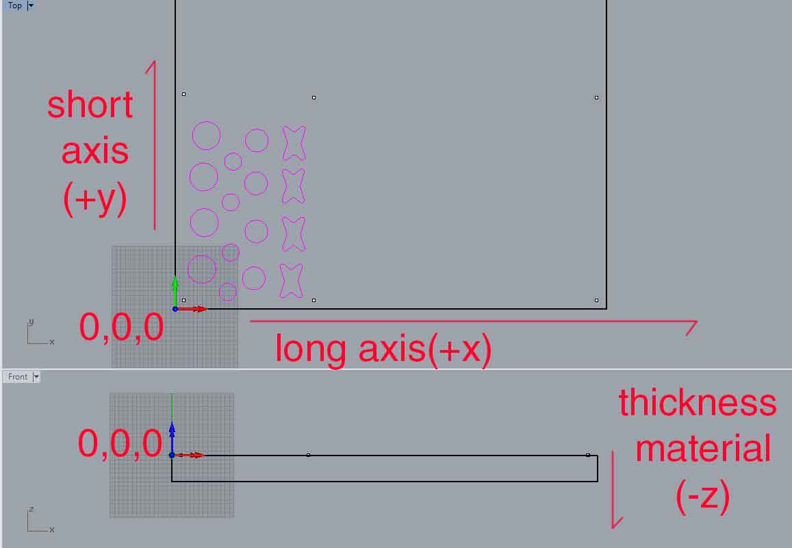
First step on rhino-cam is to set a 3d stock. All my pieces were 2d cuts, so I only had 2d curves on the drawing. I created a box with the dimensions of the material and its thickness. It is important that the 2d curves are on the top of the material and that it is set on 0,0,0.
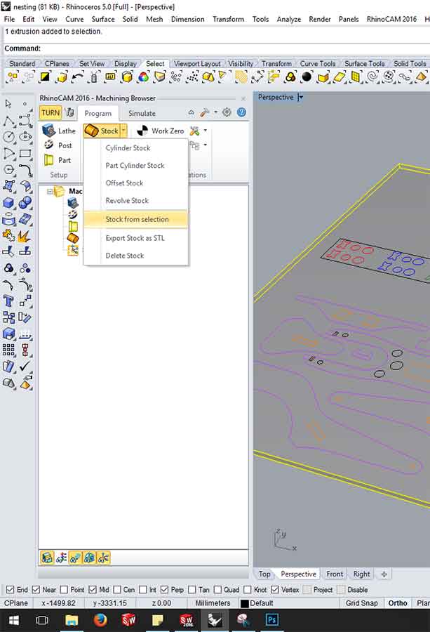
After the 3d material is modelled you open Rhino Cam and click on STOCK, STOCK FROM SELECTION.
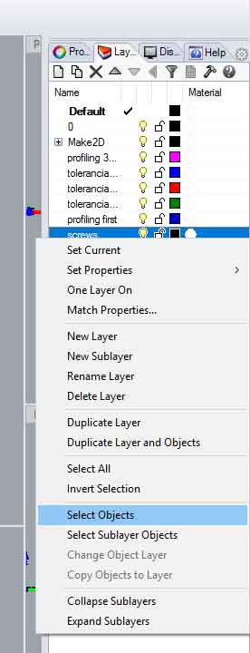
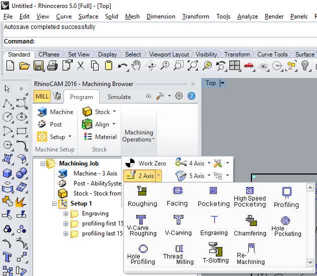
Now is time to set the strategies. The most common 2D are engraving, pocketing and profiling. In this first piece, I have used engraving for marking were the screws are and profiling for cutting the pieces. It is good practice to set the drawing on different layers depending on the strategy they will follow. This makes selection much faster later, as in rhino if you click right button on top of a layer, SELECT OBJECTS, you can select all the objects on a layer.For setting the strategies, if you click on MACHINING OPERATION, you can choose between a series of options. I went straight to 2D Operation.
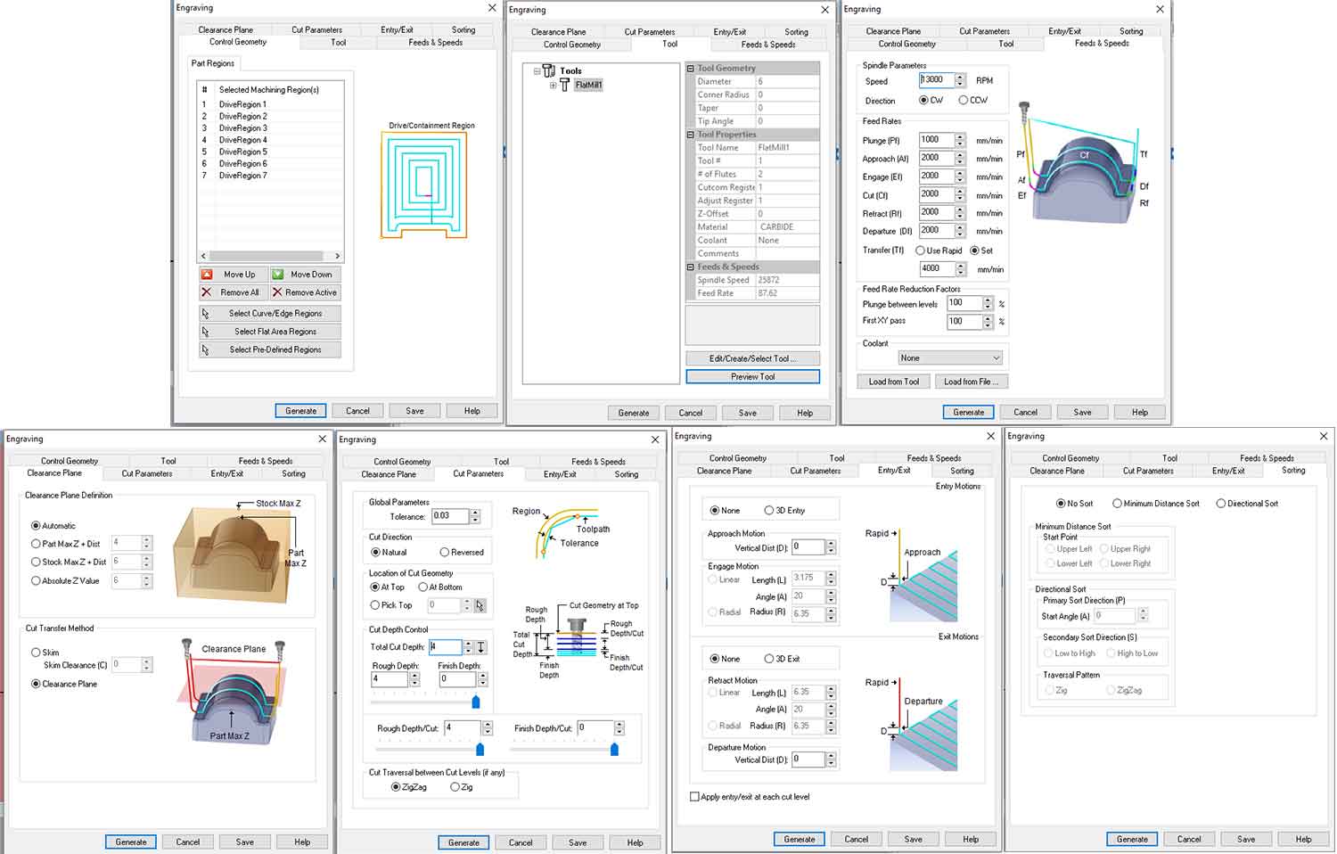
The screws will maintain the material stuck to the bed and flat. It is like the double-sided tape we used for milling PCB's. I engraved the position of the screws and drilled them afterwards. It is very important to mark where they will go, to make sure they don't interfere with any cutting line, as the tool would break if it touches a screw. Once they are rightfully placed we select the engraving 2D operation and start going through all the tabs that the software gives us. CONTROL GEOMETRY: we click select curve/edge regions and select the geometries on the screen. We can do it by selecting layers or selecting every item on the screen one by one. TOOL: If we have one already created we just choose it from the option. Otherwise we have to create on Edit/Create Select Tool option. There we can choose the kind of tool we want but the real important thing is the diametre. FEEDS & SPEEDS Here I used 1300 Speed, 1000 Plunge and 2000 for the rest of the values. This depends mostly on the kind of material you are using. CLEARANCE PLANE It defines how hight the tool is travelling up for movin in x-y axis. I used automatic values as my material was a 2d sheet. CUT PARAMETERS This is very important for the tool's health. Here you set the amount of material that the tool takes on layer. As the top and bottom. It is better not to take more that 3-4 mm each time. This also depends on the material you are milling and the quality you want. ENTRY/EXIT This sets the way the tool starts the path. Most of times we will choose none. SORTING this is for choosing the options on the path order. I used Minimun Distance Sort.
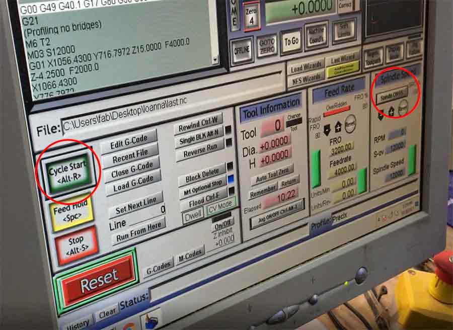
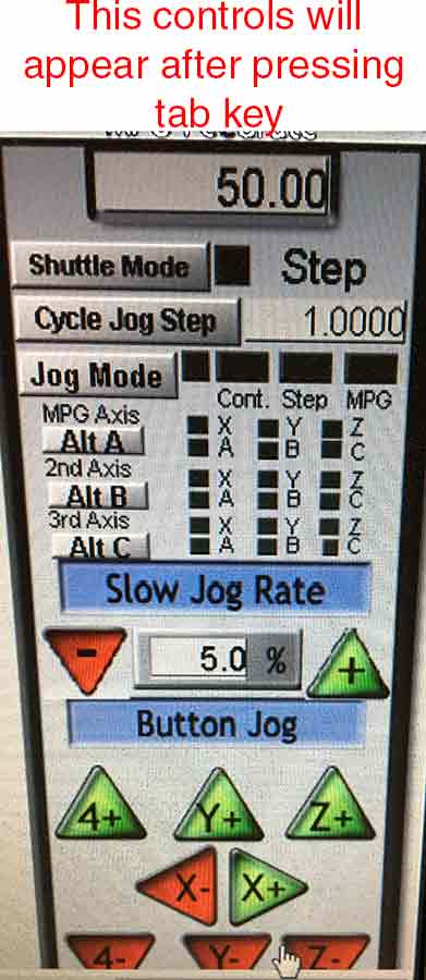
We have two milling machines here at our lab, I have used for this assignment the PRECIX machine. It runs with Match 3 MM software. This is a very scary software at the beginning as it has tons of blinking lights and seem to be super complicated. At the end of an afternoon of milling I was much more comfortable with the software and the machine. The first thing is to set the 0,0,0. The center of the tool must be on the 0. This is done very similarly as with the Rolands, with the arrows on the screen and varying the jog steps you carefully set the x,y,z. The arrows to control the movement of the machine appear and disappear by clicking tab. Once the zero is set, I loaded the g-code. It was on a USB-drive on the computer that runs the machine, by going to FILE, LOAD G-CODE, I selected my file. After is was completely loaded, I started the spindle, by clicking on SPINDLE CW F5. Our machine sometimes has trouble starting, and I had to restarted a couple times before I got the spindle to start. Once the spindle is running, you start the milling process by clicking CYCLE START ALT-R, the machine will start milling.The process is the same for all the strategies, you just need to through them in the right order.
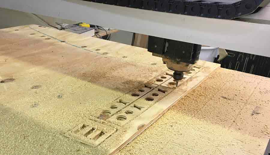
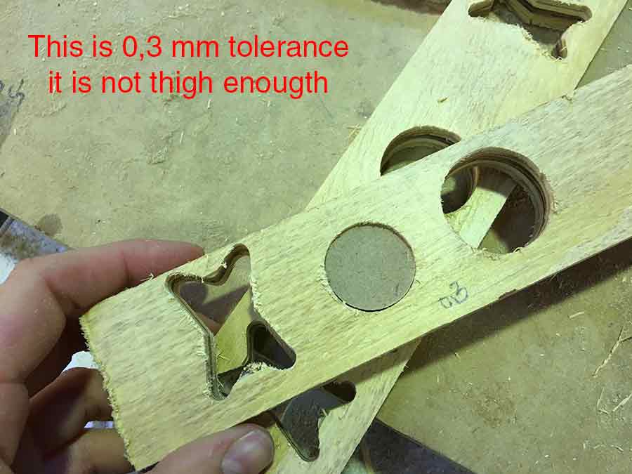
Once I did the test I realized that the right tolerance was 0.2. With 0.1 the MDF would go through but there is so much tension that it would break. 0.3 was too loose, I could rotate the circles.
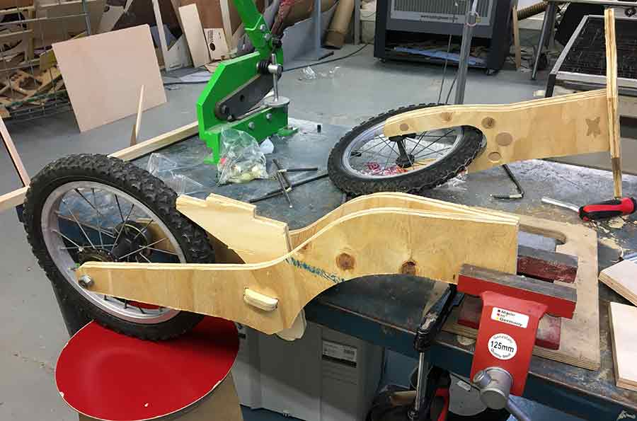
This is the process where I learnt the most about the design. While assembling, I realized a lot of things that could have thanked a better design. The first one, MDF was definitely not the right wood for doing the friction joints. Once the whole thing was hold up together (no glue) there was too much tension inside that the MDF started breaking inside. I also realized while assembling that on my design you could not take out the front wheel, so in case of a flat tire the whole bike would have need to be destroyed. Also, the system to hold the front wheel, where the most tensions are generated was not sturdy enough. I am happy with the overall result, but I will only consider it a prototype, and I guess that my niece present will have to wait for a design improvement.