
Shown how you made and programmed the board.
Explained any problems and how you fixed them.
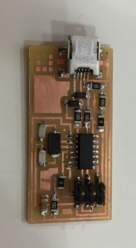
Included a 'hero shot' of your board.
I was very excited about this week as electronics are something totally new for me. Unfortunately, I started the week with some trouble with SOLIDWORKS and that took me a couple of days to fix. I started using the software on week 2 for the computer aided design assignment, and I used it also for week 3's parametric design and it worked perfectly fine. Actually, I was very excited about the possibilities it offers compared to other software I was more used to. Suddenly, it started giving me graphic problems. When I opened a part, first the screen used to get black for a few seconds, and after that, the software run very slow. It was impossible to work with it. I tried to uninstalling and reinstalling, but the problem persisted. With Arnau's help we were able to fix it. It turned to be graphic card driver's problem. It is very important to update our drivers as we are running a lot of different softwares every day.
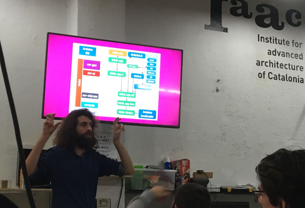
After Neil's class on ISPB and electronics production, most of us were very lost. I don't have any electronics background and as interesting as it might be, aproaching such a complex subject is a little overwelming. That is the reason we had a class on basic computer architecture and microcontrollers from Guillem Camprodon. This was super interesting as I didn't have a clue on any of it and all the concepts as basics as they were, built a base that I believe will be useful for future understanding of electronics. Here we have a link to the class, because I believe it might be a useful introduction to the subject.
The first question we had was, what is FabISPB? & What is it used for? It is an in-system programmer for AVR microcontrollers, designed for production within a FabLab. It allows you to program the microcontrollers on other boards you make. When we make a board, we will mainly use AVR microcontrollers. For programing these, we need something that help us translate the instructions from our computer to our board. This is the role of the FabISP. This as simple as it is, was a concept it took me a while to understand.
The process for creating the FabISP is first to mill the copper board. We are using a design that is already done, so we only had to download the png for creating th g-code. Afterwards, we have to weld all the components on place and program the board.
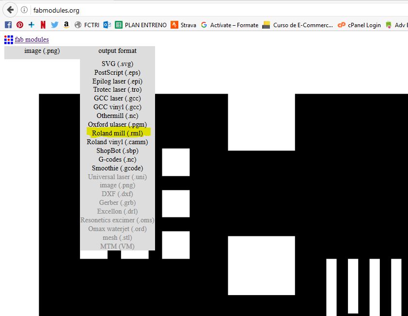
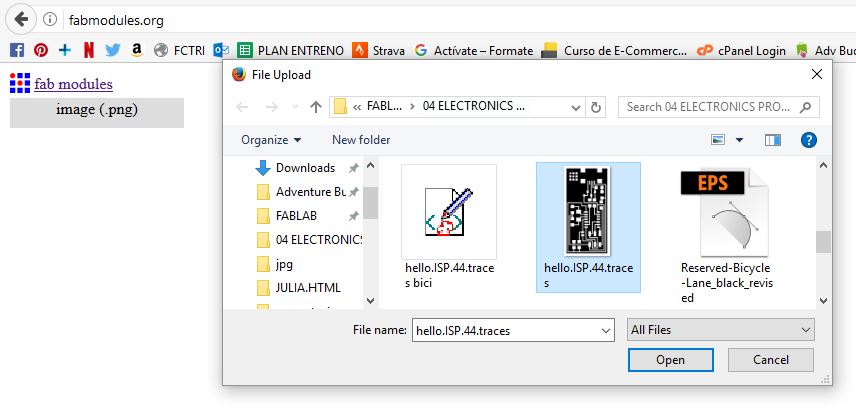
On Thursday, Santi gave us a tutorial on how to use fabmodules app and on the use of the electronics milling machine. We have a couple of Monofab roland milling machines. From all the boards that were introduced to us on Wednesday I chose Neil's design because is the most documented online from previous years. I downloaded the files from the archive (the traces png and the output png) and opened fabmodules. It is important that the file is on black and white, as fabmodules detects the contrast points were white meets black and trace the g-code lines.
.JPG)
.JPG)
%202.JPG)
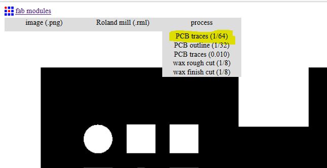
On fabmodules, as input format, I used png and chose hello.ISP.44.traces png from my computer. As output format, Roland mill. Finally, as process, PCB traces (1/64) for the inside traces of the board and PCB outline (1/64) for cutting the outline of the board. There is also the option of PCB traces 0.010 which are only used on tiny circuits.
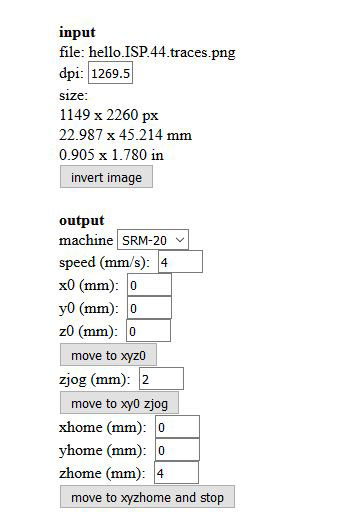
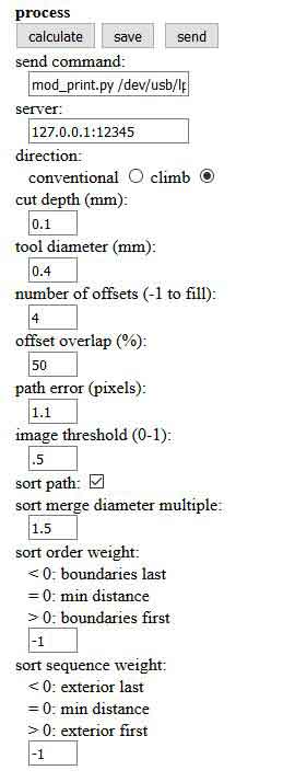
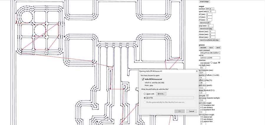
Once we have done this, a panel on the right part of the screen will appear. The first thig we have to set is on OUTPUT the machine which is SRM-20. On x0,y0 and z0, we set the value to 0. On the homes, all the values should be set to 0 too, but apparently the zhome has a bug and in order to work fine without scratching the board during the milling we should write any value different from 0. So these would be xhome and yhome 0, adn zhome 4 (for example). On PROCESS part we have to set the cut depth 0.1, the tool diameter 0.4 and the number of offset to 4 (This is the times the machines run out from a trace, it coul work with one, it just makes it more dificult to solder afterwards. If you set this value to -1, the machine will remove all the copper that is not a trace making a nicer look board, but taking more time to mill.). Afterwards we have to press CALCULATE, we will se the paths the machine will make to mill our board. And after having press calculate we have to SAVE it. The app will generate an AutoCAD Redline Markup Language (.rml) file.
Once we have the traces we have to generate the paths for the outline. Once we have choose our png from our computer and chose the output roland mill, we have to select the 1/32 bit. There are some presets already make and only have to make sure the x0,y0,z0 are set on 0 and the xhome and y home are set on 0 while zhome is set on anyother value as before. What we have to make sure is that the number of offsets is 1, cut depth 0.5, stock thickness 1.5. Now we can send the files to the computer connected to the milling machine.
First thing is to tape the board to the bed using doble sided tape. We have to make sure we press evently trhough the whole board in order to get it evenly taped. It is very important that the bed is flat, to avoid problems on the milling later.
The software the machine uses is Vpanel for SRM-20. It is a very simple software. It only uses x,y,z origins, speed and spindle speed parameters. The first thing is to set the x, y origin. This is not a critical point yet. Once this is set we start to set the Z. We basically have to put the spindle touching the board. The issue is that this has to be done very carefully as the tool is very sensitive an easily breakable. There is a trick to do this: first approach it as much as possible with the controls and when it is close enough unscrew the bit and lower it gently with the hand till it is touching the board. Now we press the set Z origin. Afterwards we press cut, the machine asks us to upload a file, we choose the one we want and press output. It is good practice to lower the machine speed at the beginning to check everything is all right. When we check, it is milling were it is supposed to, we speed it up to 100% again.
.JPG)
.JPG)
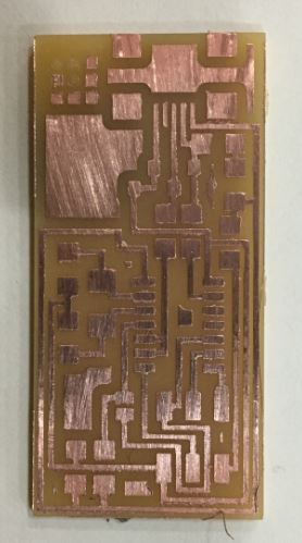
It took the machine about 10 min to do the whole thing. Unfortunately, the bed was not flat enough. My board was the second one from a bigger piece, maybe when the first one was released the board was left uneven. The problem was that the bottom part was not completely milled. The shiny area on the bottom of the board that can be seen in the picture is not completely removed copper. It took me a while to get it right. We set again the Z origin, touching the not milled area and lowering with the x1 step from the motor and through the machine again. It failed too. We did it again lowering x3 steps. This time the spindle was loose, and the machine was milling without control. This happens when there is too much length of the tool left out, and there is not enough grip. Thankfully as we started with 20% speed, we could stop it on time and the only affected part was the MIT bits and atoms logo on the board. We fixed the looseness of the spindle by lowering the Z and lifting the bit.Finally, I got a completely milled board. The edges were super rough though. I had to use the blade very hard to smooth them up. I was a little scare that having pass the machine so many times the lines might have been broken on some points, so Xavi told me I could use a multimeter to check it and everything seemed to be right.
.JPG)
.JPG)
.JPG)
.JPG)
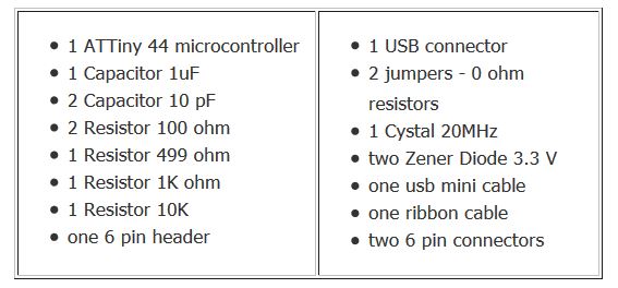
Soldering time had arrived! I was scared and excited at the same time. First we had to find all the components on the electronics drawers. It makes everything easier to write down the list of components and tape them to this list. This allows us to be sure we have everything we need and and make sure we don't lose anything. It is like doing a "mise in place" when cooking.
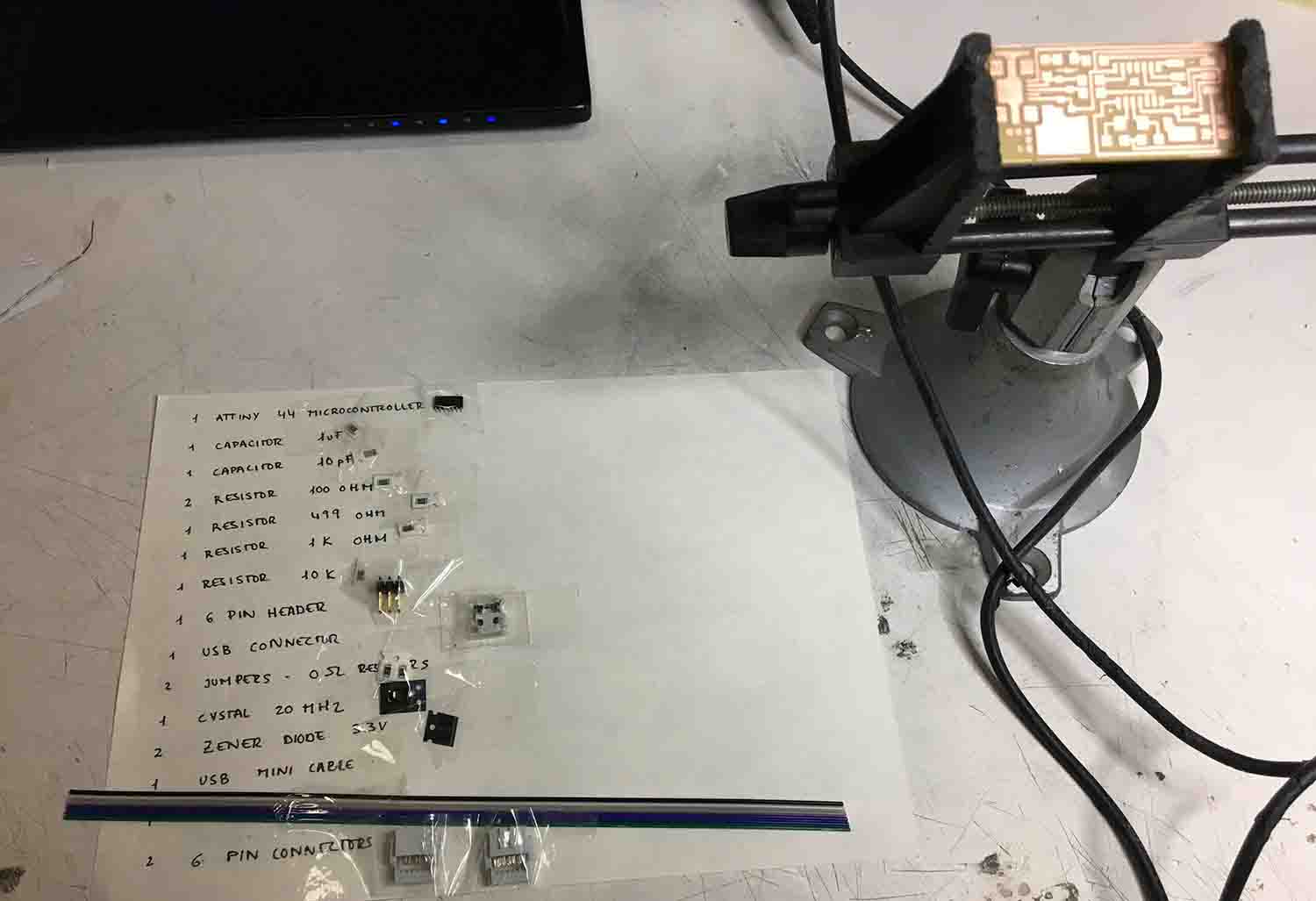
I was scared and excited at the same time. Esteban, who knows a lot about electronics gave me a few advices on soldering. Those were very useful. He told me to start from the flattest to the bigger ones. So, the order would be first resistors, microcontroller, capacitors, diodes, crystal, 6 pin head and finally the usb adapter. Unfortunately, by mistake, I soldered the crystal before the microcontroller and this made very difficult to sold this last one. I must admit it took me a while to do the whole thing...
We have discovered that Windows doesn't really recognize the drivers. A couple of my classmates spent lot of time trying it so I decided to try something else. I tried to install Virtualbox, to run the drivers on Linux. It didn't work, because the virtualizing options from my computer were disconnected and I couldn't fix it from the BIOS on that moment... I hope that with more time I will be able to fix this other with the virtualbox, or getting the Atmel Windows toolchain to work. I ended up doing this from Pablo's computer, as he uses MacOS.
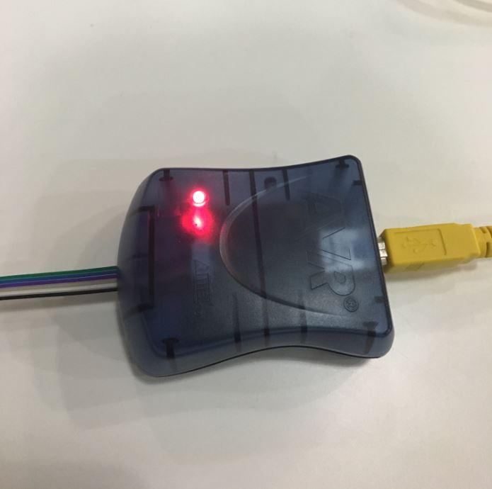
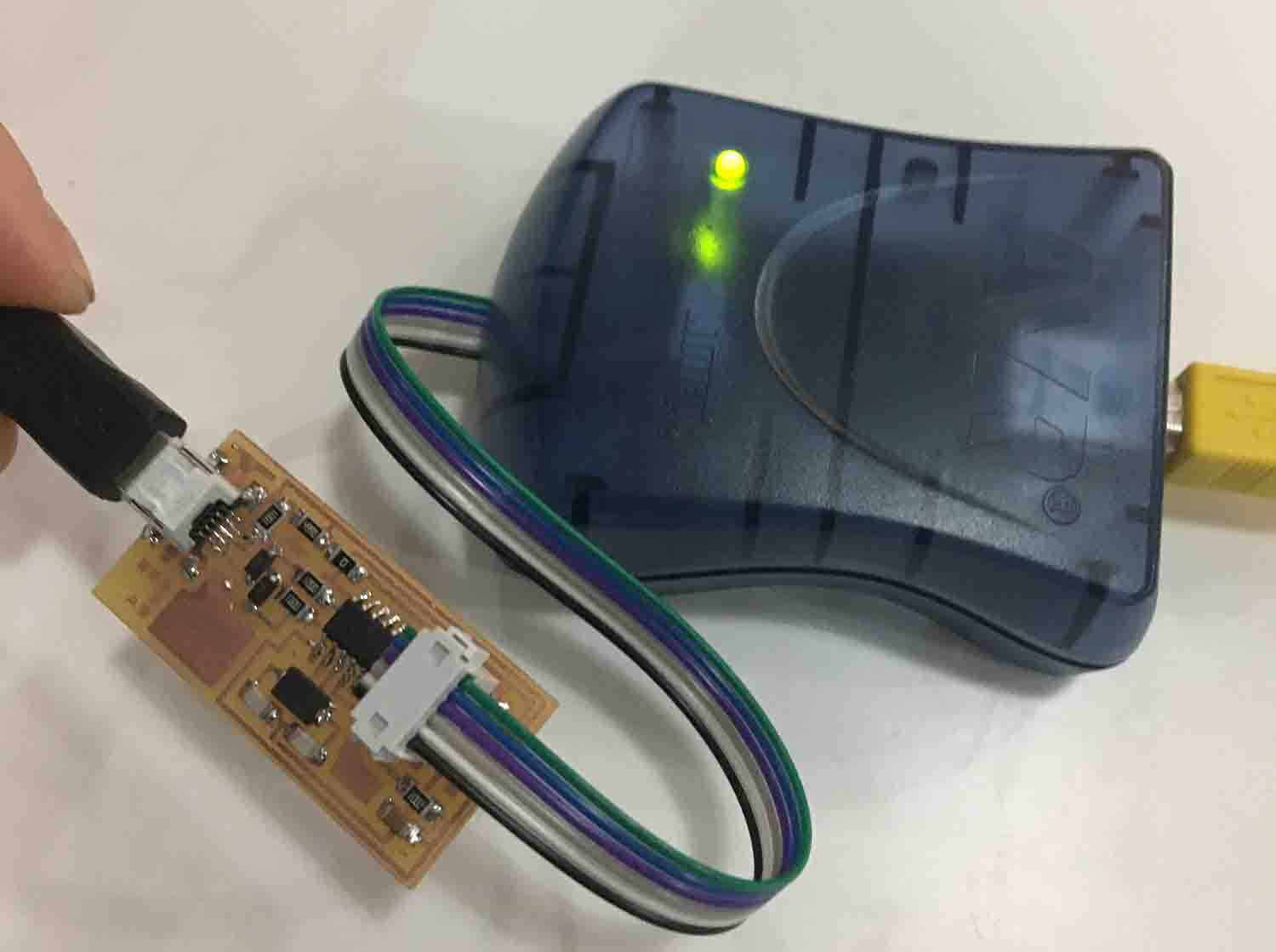
First, I connected the 6-pin connector cable to the FabISP. The black cable is the ground and it has to be connected to the GRD pin which is the right on the bottom. After, I connected it to the programmer and this one to the computer, a red light appeared... Oh, no!! Thankfully, Pablo realized this was because the mini usb cable was not connected to the computer, we did it and a green light appeared (relief!).
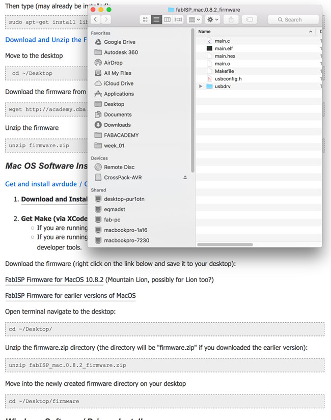
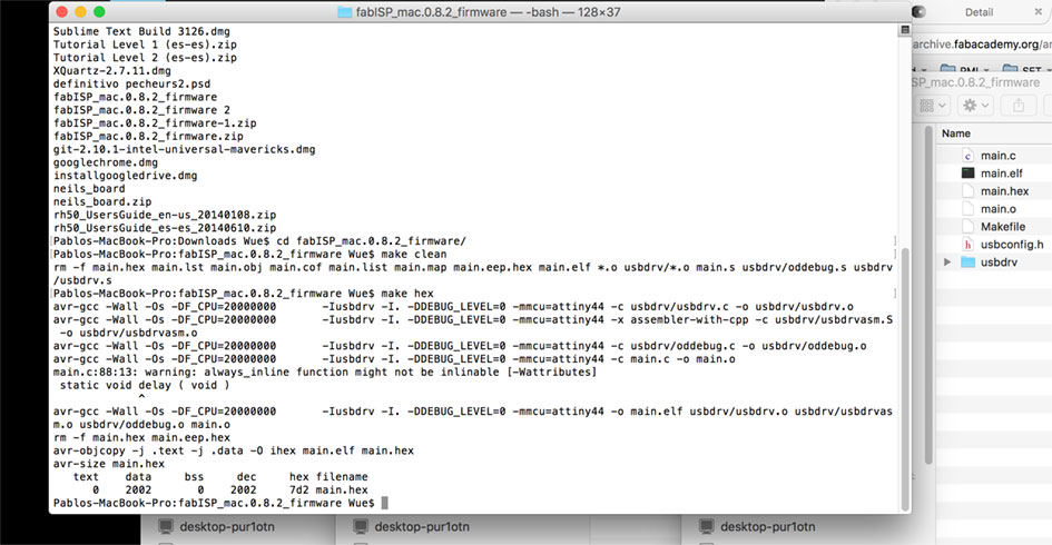
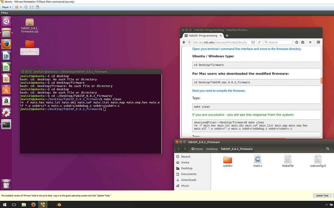
The first step for programming the ISPB is to download the FabISP Firmware and compile the firmware. Then we use "make clean" instructions.This is for making sure there is no previous firmware installed.
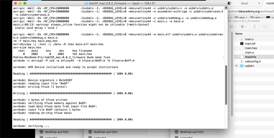
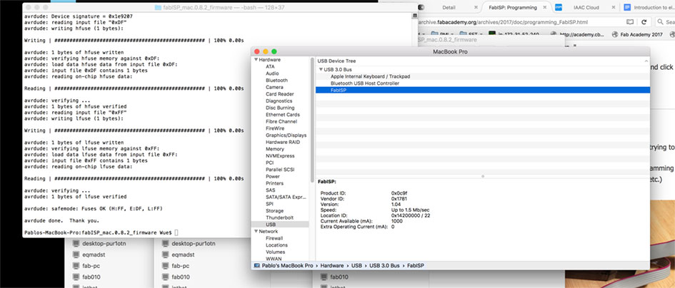
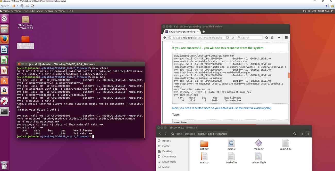
Next instruction we type is "make hex". Right after we have to set the fuses so the board will use the external clock (crystal) by typing "make fuse". And finally program the board to be a ISP by typing "make program". Now, to check that everything is all right we have to check if the computer recognizes the FabISP. The last step would be to remove the 0 ohm resistors.
Next week after having gave up Virtualbox, I tried the other virtual machine software there is VMware . I installed. I downloaded Ubuntu from its webpage and burnt an ISO. I installed the ISO Ubuntu on the VMware virtual machine and finally was able to use Linux on my Windows machine. Once I started sesion on Ubuntu, I followed the Fab ISP programming tutorial for download the firmware for Linux.
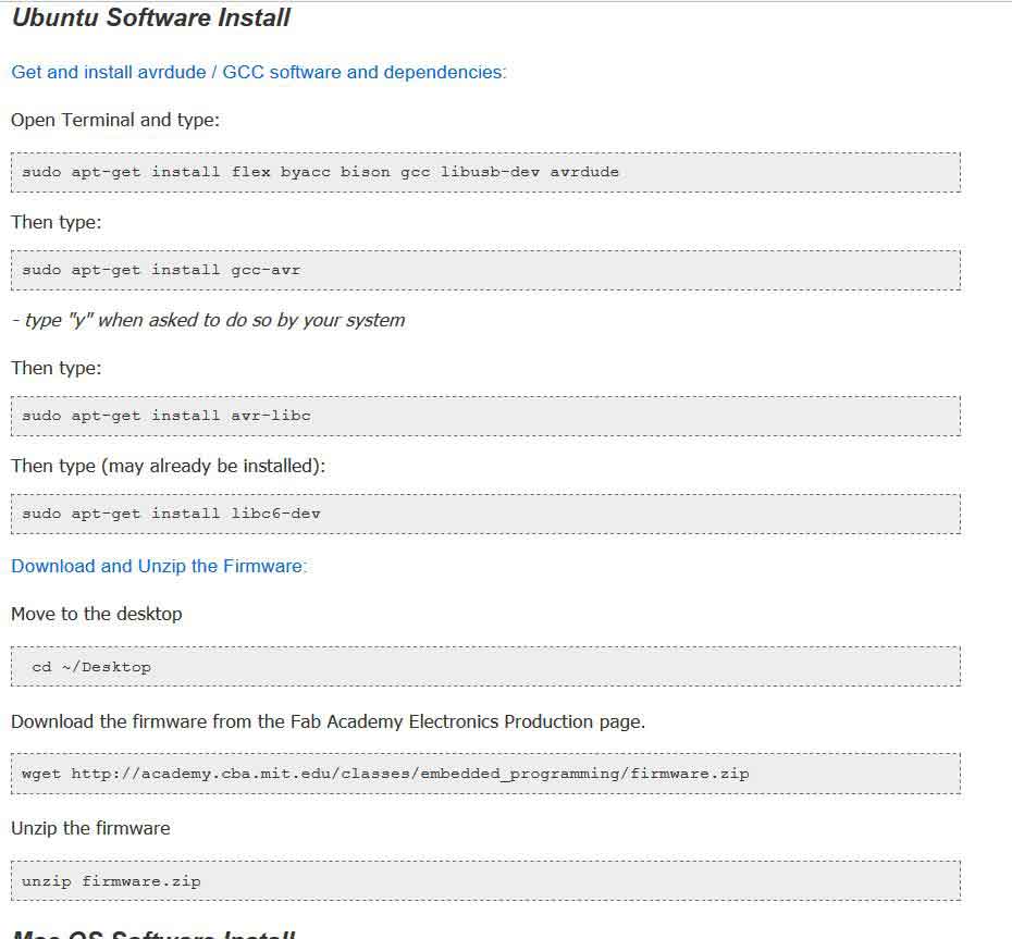
After the software is installed and compiled, the steps are the same than in mac. "make clean","make hex","make fuse","make program".
BACK HOME<<<