Modelled experimental objects/part of a possible project in 2D and 3D software.
Shown how you did it with words/images/screenshots.
Included your original design files.
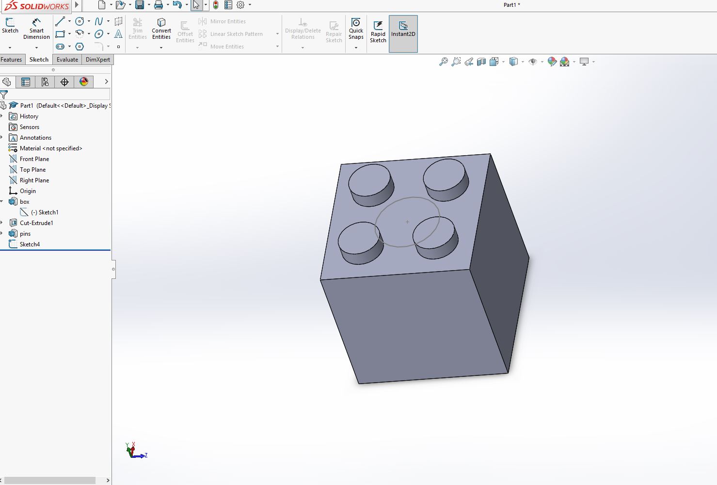
On week 2 we had to try several 2D/3D softwares and render an image of our final project using different software. The main goal was to try new software for 2D and 3D modeling. On Thursday, we had a class on Solid Works basics. I had done a lot of AutoCAD and Sketch up and some Rhino, so I thought this could be a perfect opportunity for getting out if my comfort zone. It was a workshop where Greg Durrens showed us the potential of the program and the way the program thinks to build geometries. I used the one year free license we got on Fabacademy to install Solid Works and got into some exploring after the class. Greg did some basics exercises with us on the class that I think are interesting to start using it. The exercise consisted on modelling Lego pieces. First a non-parametric Lego piece. Afterwards do the same piece with parameters, and end up building an assembly with them. I find Solid works a very powerful modelling tool. It reminds me of how Revit works, but instead of having constrains between structure and architectural elements between other parts of the model. I guess that at the end a building model made from different parts is just a scaled version of every other model.
On Friday, we had a Rhino tutorial. As I already knew the program I haven't done many iteractions with it. On the other hand, we also did a grasshopper tutorial on Monday. I had also used grasshopper on the past, but it was a very long time ago, so I want to get back on it. We didn't have much time so we basically watched Aldo doing an exercise while he tried to explain us the way we must think to use the program and the potential of grasshopper plugins you can find on food 4 rhino website. The challenge was to do the exercise back home. Aldo also linked us to a Rhino/Grashopper tutorial he gave for FabAcademy 2014.
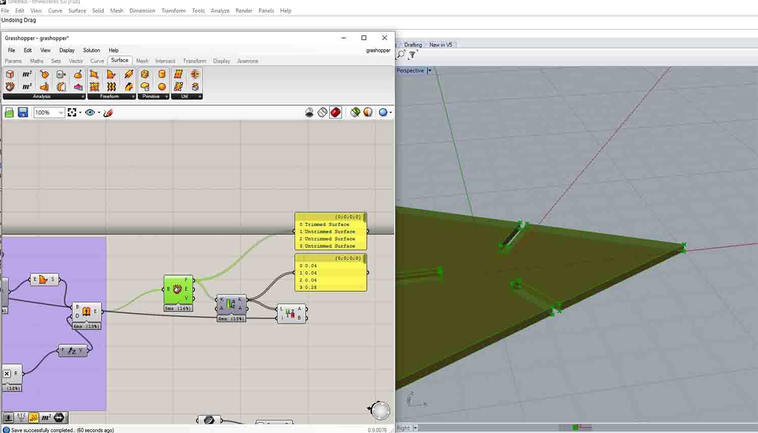
The first step was creating a polygon. I started with a triangle, as Aldo did, but leaving the number of sides as a parametric slider. After, the goal is to create a rectangle on every side of the polygon. This will be the assembly line. I struggle a little with the right placing of the rectangles, but at the end I managed. The important step is to align the rectangle planes to the tangent plane of each polygon side. With an extrusion after a Boolean subtraction we have our piece defined.
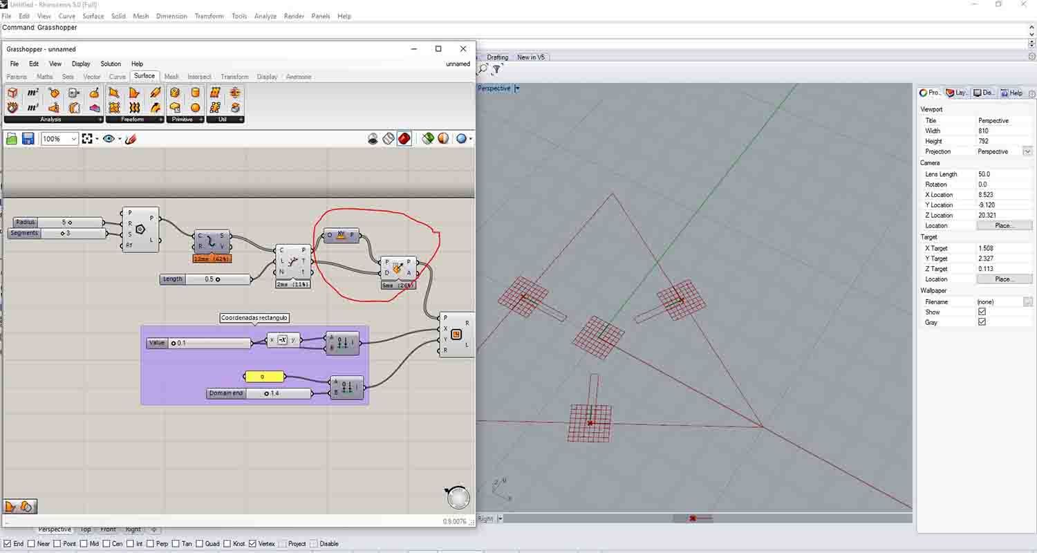
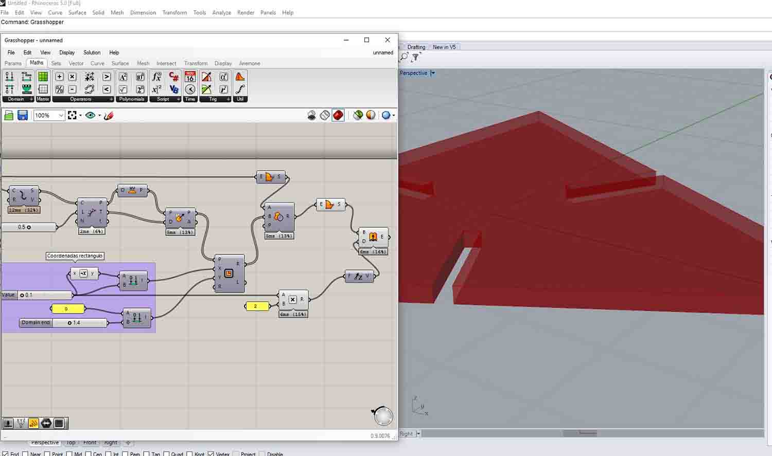
After that we are supposed to explode our piece and analyze which slot is closer to an external spline point. Here is where I got stuck. I will correct it with a little more time, but still haven't figured it out.
We also had an intro to Blender. It was mostly an interface introduction. It works with meshes, I realized I have no clue on how to work with meshes and I really want to learn. Unfortunately, this week the most I could do with blender was download the software and look around its webpage to realize how big potential it has.
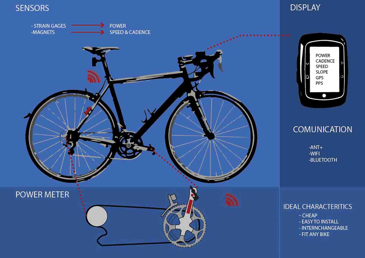
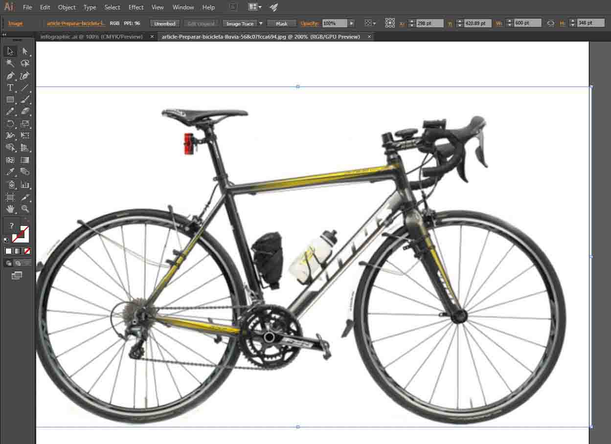
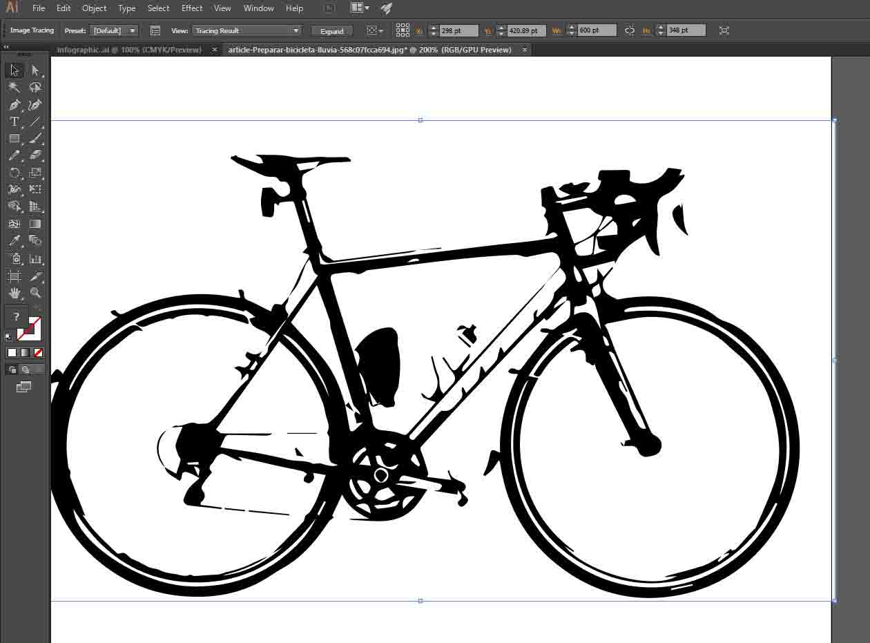
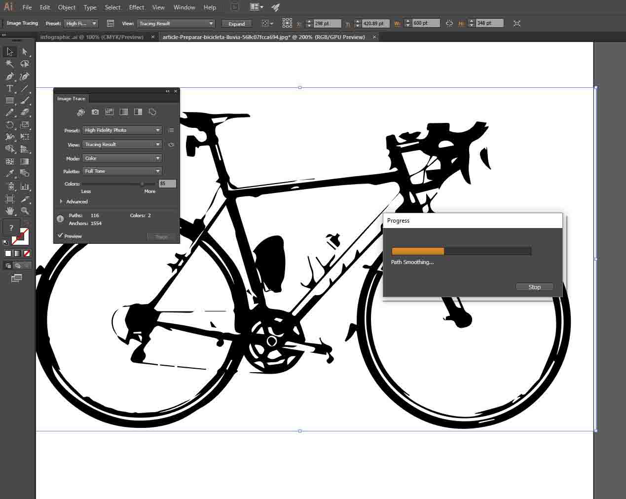
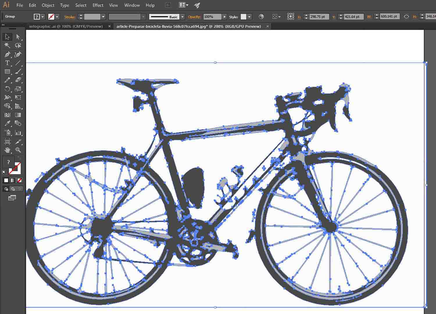
I wanted to try Inkscape to render an infographic of my final project idea, but we didn't have time this week to do the tutorial. Even though I downloaded the program and started playing around with it. Unfortunately, I spend most of the week already dealing with a new software (Solid Works), so I finally did my infographic on Adobe Illustrator which uses Scalable Vector Graphics (SVG) as Inkscape but I already had experience using it. Vectors allow us to print on any scale, as the info is not contained on pixels. As it works on mathematics operations, it also let us use more complex transformations as Booleans. I also has a really nice feature, such as Image tracing, which allow us to vectorize any image document to have control on its modifications.
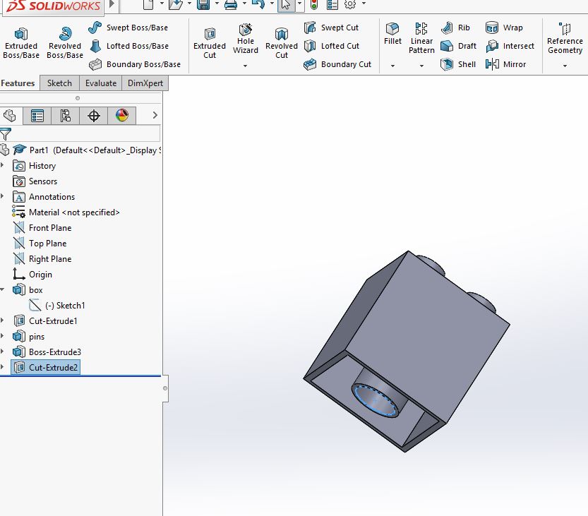
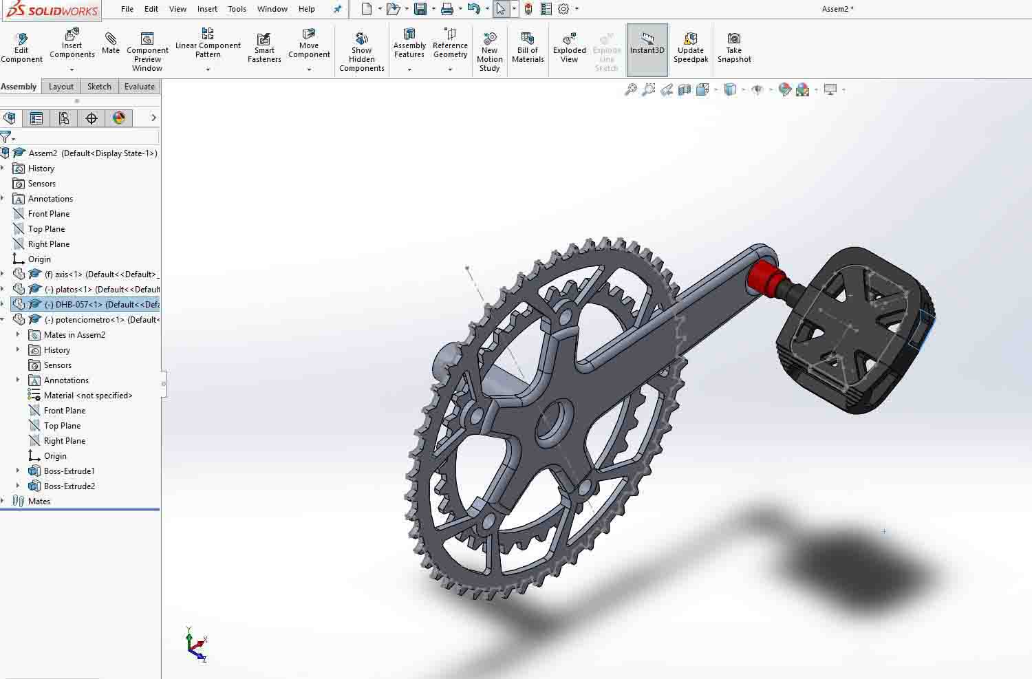
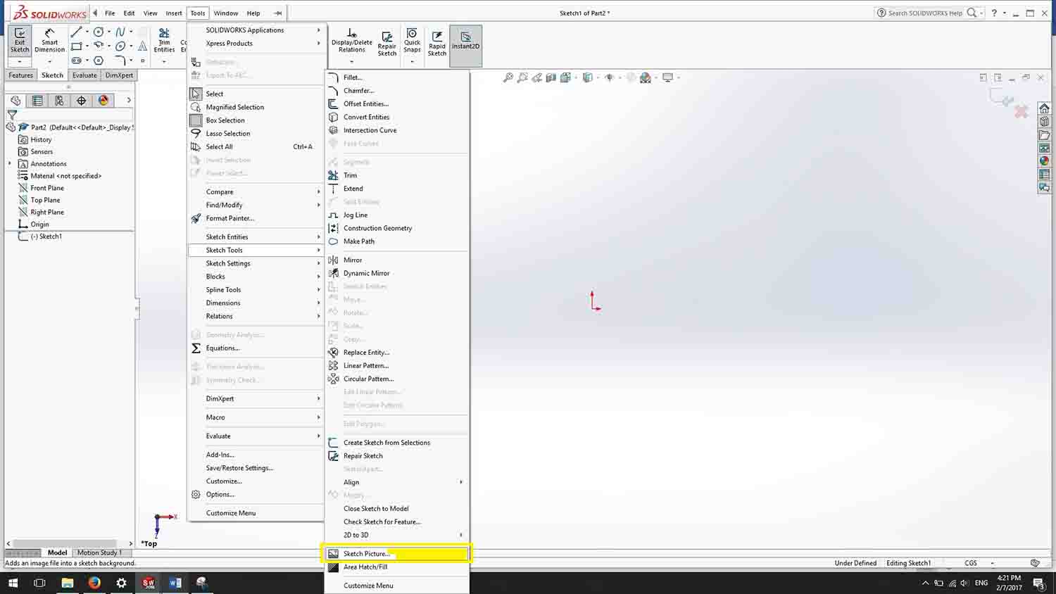
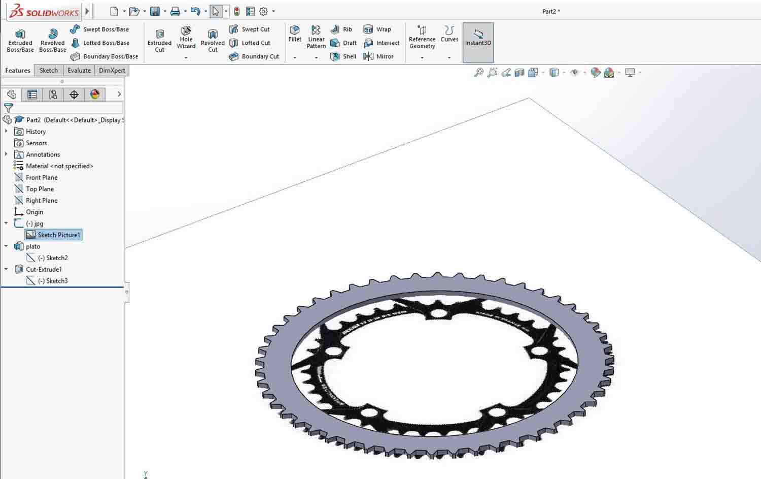
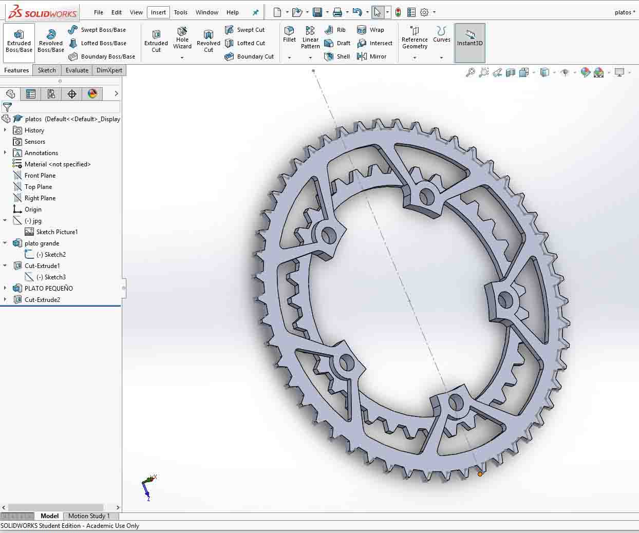
I wanted to work with Solid Works on this week's assignment. To begin I wanted to model the plates, the crank, and the spider of a bike. My final project consists on a bike power meter, I still don't know where I will place it. There are different options. On an accuracy point of view, the closer the device is located to the cyclist the better. This means that the pedal or the shoe are the most precise places to have the power meter. There are also lots of models that are located on the crank. It is an easy approach to the problem. Also, there are other options that are inside the pedal axle, it has interferences with the traction of the chain, but it is safe from bumps, dirt, and rain. As I have not decided where I will place it, I decided I would model the transmission system. To start I import a jpg to Solid Works, to do this you must start a sketch, go to sketch tools, and choose sketch picture. Having this as a template I did a polar array of the teeth. Afterwards I did the geometries for the extruded cut.
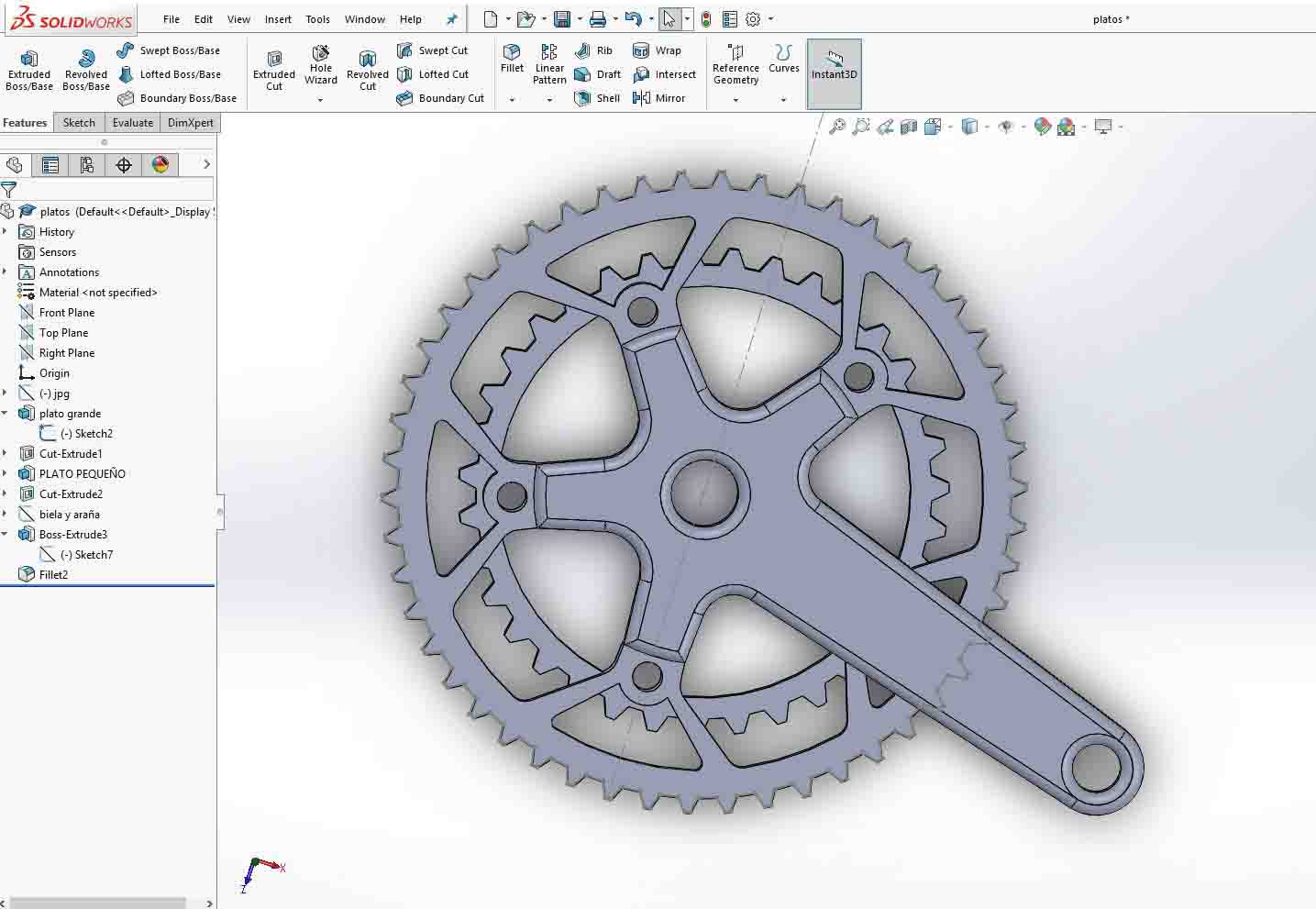
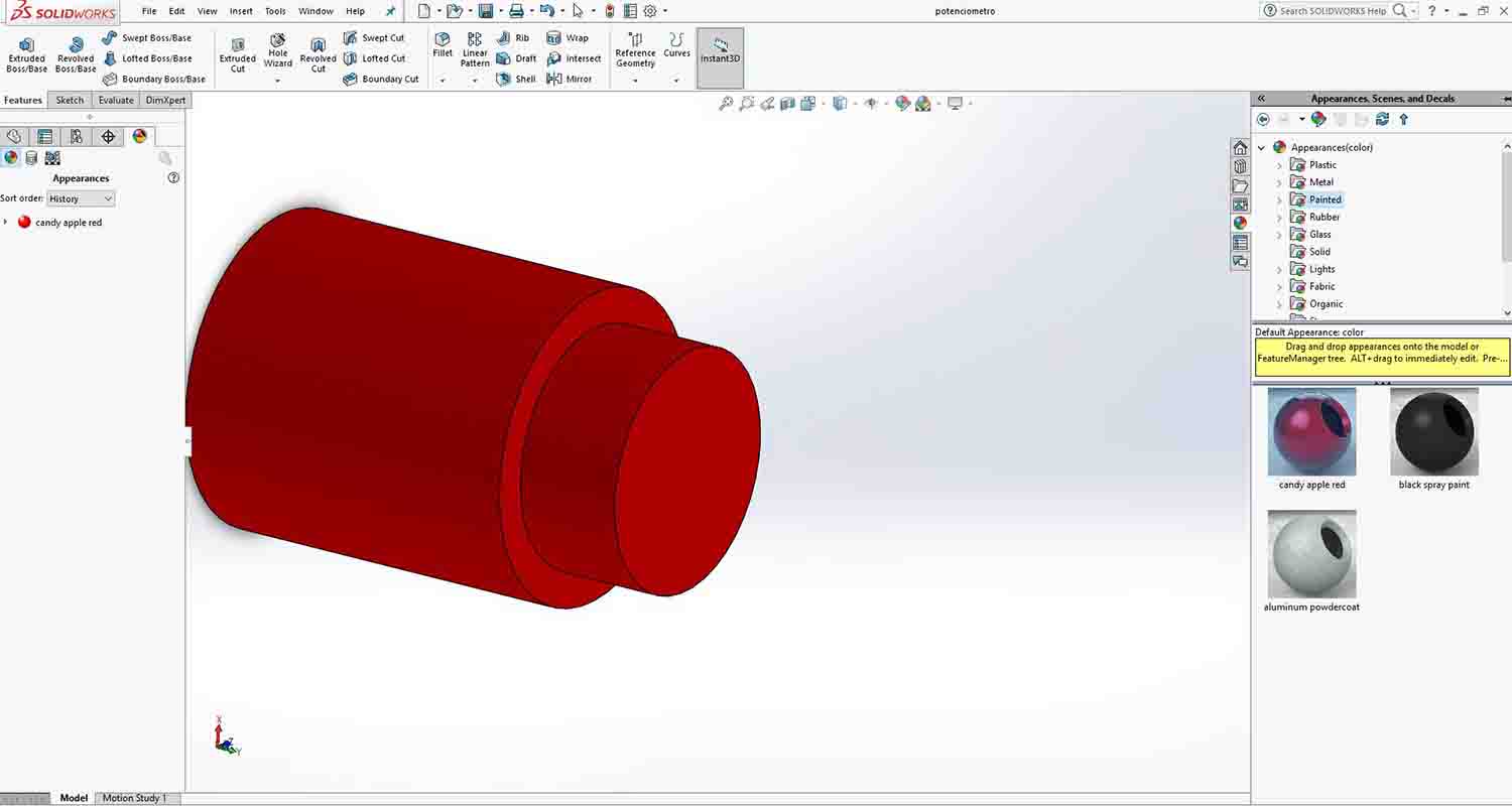
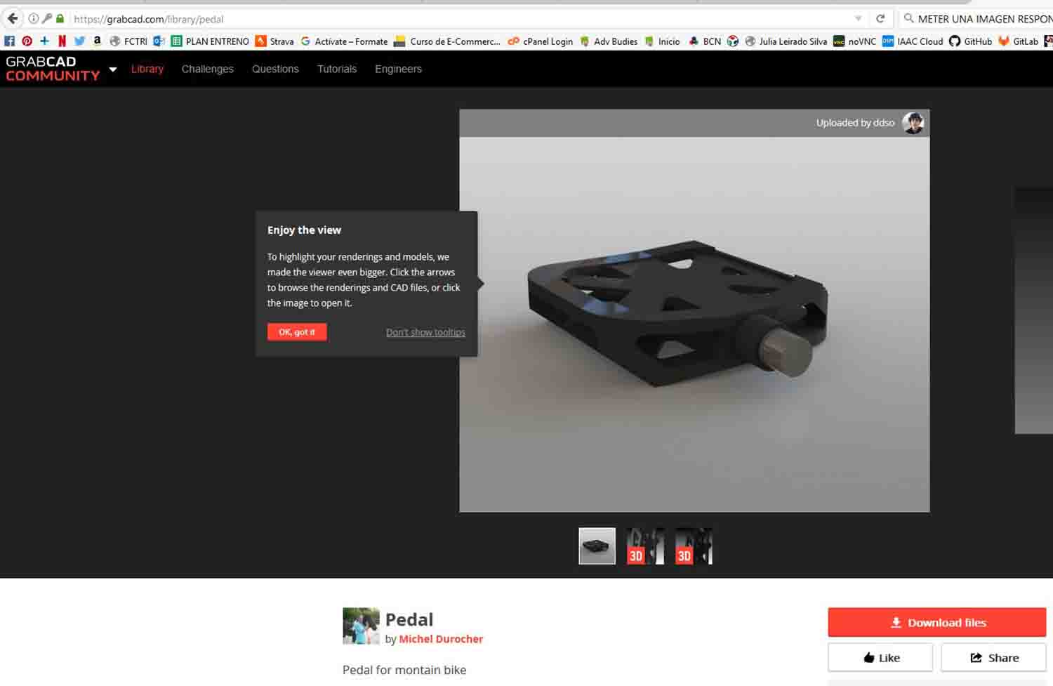
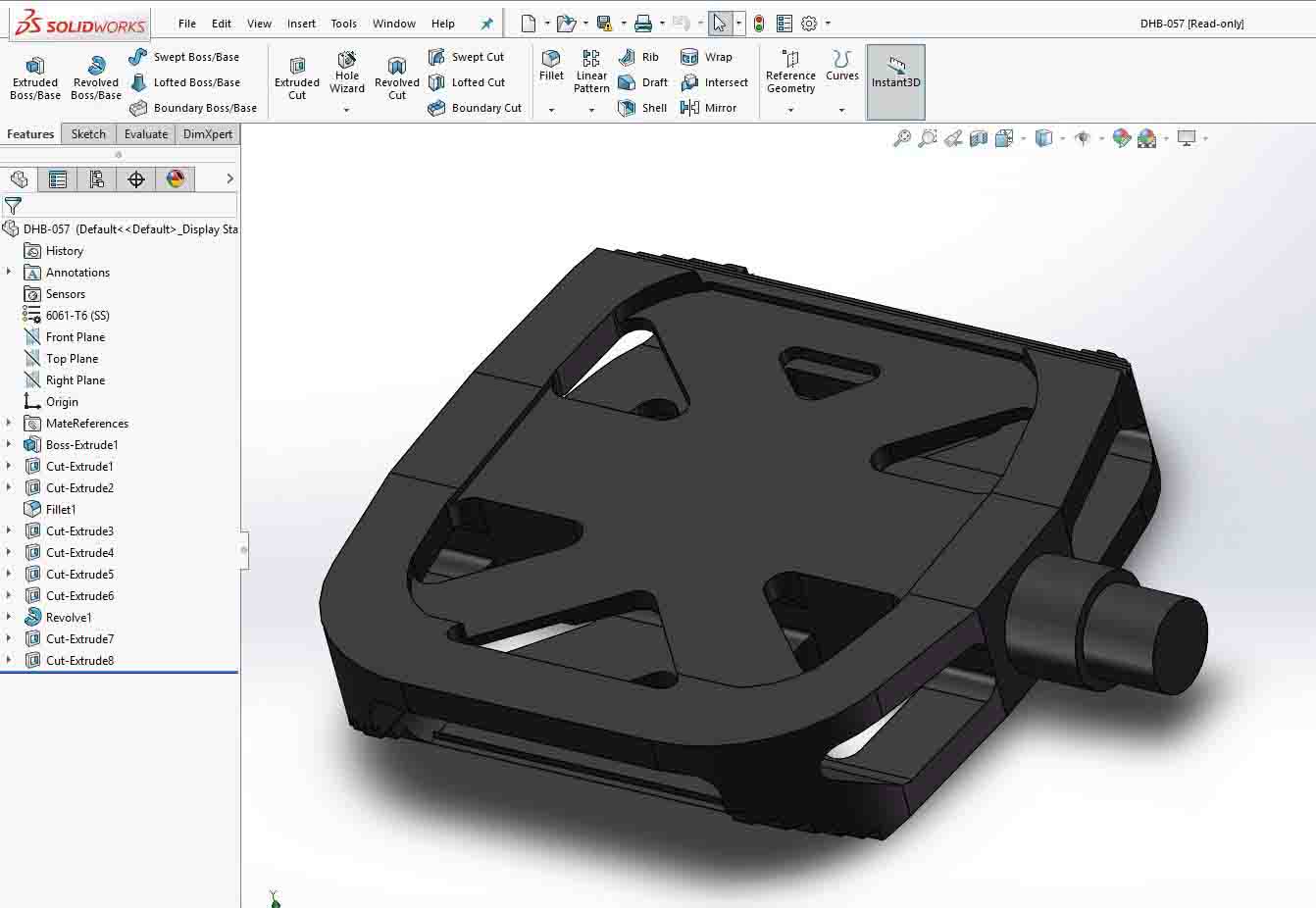
Once I had the basic main part modeled, it is time to model my power meter. I based my model on LIMITS power meter, which is placed between the crank and the pedal. I wanted the device to pop up when all the stuff was assembled Appearence Edit, open libraries, and you choose a material on the right panel. After modeling the power meter, I wanted to search the community around Solid Works, so I search through different servers for an already modelled pedal. Finally, I downloaded one from GrabCad. I built the assembly with the different mates. After fixing the axle the whole thing spined around. I have recorded a video of the working piece. It was the first time I recorded my screen and as I work with Windows I think the only way of doing it is with a program. I downloaded Screen Recorder. The free version allows to record 5 min of video.
I consider I have learned the basic modelling skills of Solid Works. I still have a lot of work to do. The model is mostly constrained. When a sketch is fully constrained it is showed with black lines, if it is not they are showed blue. I didn't manage to get all my lines on black... So my further goals are to get a fully constrained model and start to use the parametric information. I also want to get a further understanding of how meshes work. I will give Blender another try and get back to be fluend on grasshopper use.
BACK HOME<<<