Ruby Sun
Fab academy 2017
Week 9: Mechanical design & Machine design
1. Idea developments
The idea starts to develop when we are facing the difficulties of capturing the whole image of the objects. We always have to turn around the object in a slow and constant velocity. After trying hard to capture the overall view of the object, there are still some areas, such as the top part and the shadowing part of the object that are not being captured successfully. Therefore, we think that a good 3D scanning machine is necessary for capturing the object in a better way.
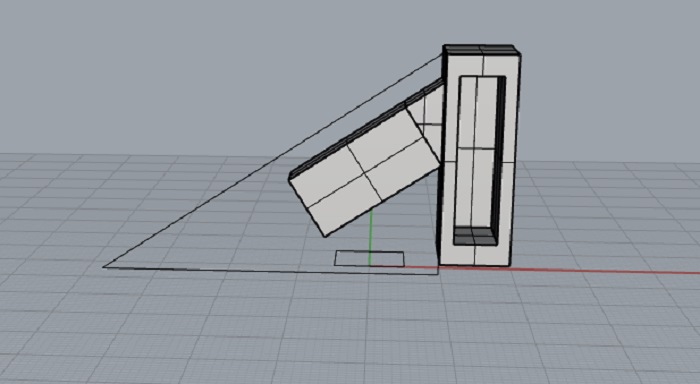
2. Machine development
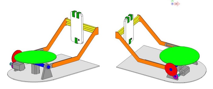
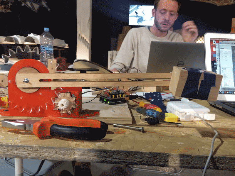
The basic structure of the 3D scanner is developed with a rotating platform in the middle and a telescopic arm for holding the mobile.
The object is being put in the middle of the platform with a motor underneath it to provide a constant rotation of the object in 360 degree. While the mobile is connected with a mobile holder, which slides horizontally on the slider. This can better adjust the position of the mobile. The arm is connected with the slider, so that the mobile can go vertically of the object smoothly. This can prevent the head or the shadowing part of the object of not being captured.
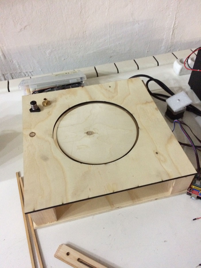
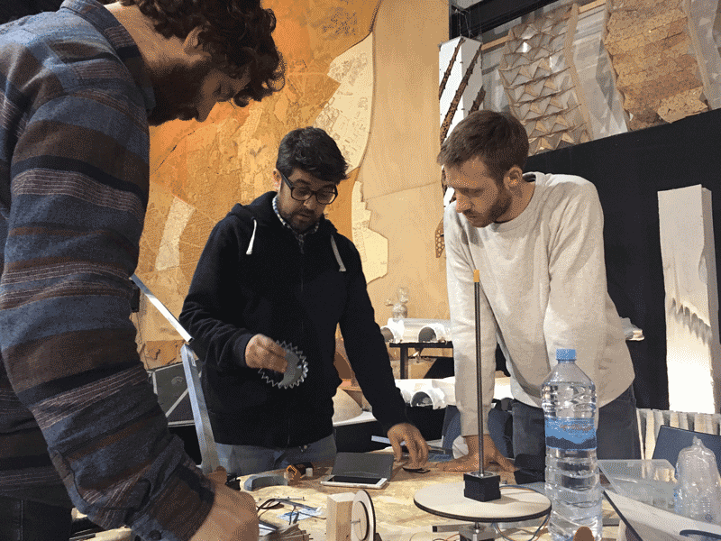
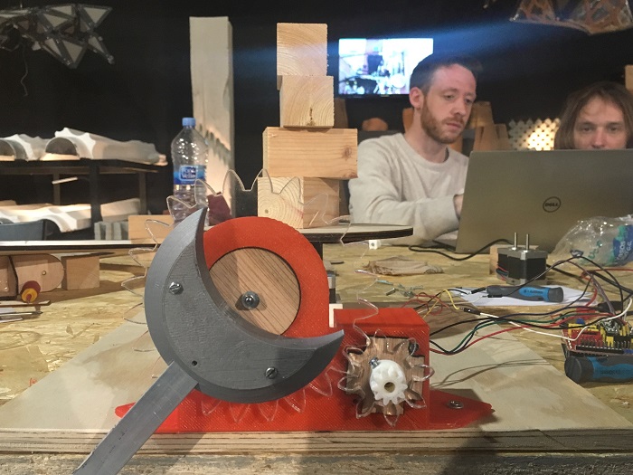
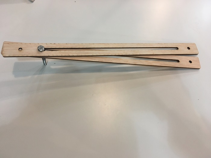
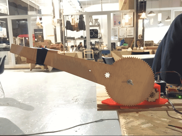
3. First prototype
Based on our inital design above, we started to make the template with woods to see how the different parts are going to cooperate with each others. We first built the base of the motorised rotating platform, followed by gears, arms, mobile holders.
4. Changes for the design
4.1 Using curve arm or straight arm?
The purpose of having an arm is to have a full vertical view of the object, so that we can better capture the head or the shadowing part of the object. We feel that the straight arm would give more support when holding the mobile, while the curve arm may bend easily. Therefore, a straight arm is chosen.
4.2 Not using the telescopic arm
At the end, we abandoned the idea of using a telescopic arm as a straight arm of 350mm is already long enough and we do not need to entend the arm further. Also, a straight arm is much lighter than a telescopic arm.
4.3 Using two arms or one arm?
Originally, we are thinking of using one arm as less material is being used. However, two arms are better as it can distribute the weight of the mobile and its mobile holder equally. This can provide a better lifting of the mobile.
4.4 Materials
As to have a strong arm, we are thinking of using aluminium, while a smaller aluminium tube put inside a bigger one. This enables the arm to be telescopic when the small one slide along the bigger one. However, even though the arm is strong, we encountered the problem of the heavy weight. Since it is quite heavy to lift the aluminium, the arm cannot be lifted when the motor and the gears are already rotating. At the end, we use acrylic or wood for producing the arm instead as the arm will still be strong with a lighter weight.
4.5 Number of engines
At the beginning, we are thinking of using one engine only for driving the arm movements. After some trials, we feel that one engine does not provide enough force to drive two arms. Therefore, one engine for each arm is needed and that's make a total of two engines for the arms. Also, one separate engines for the platform rotation.
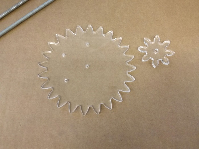
4.6 The size and shape of gears
After some experiments of the gears, there is a need of changing both the size and the shape of gears. It is because even though the motor is moving, it does not provide enough force for driving the arm upwards. We make the bigger gear to become smaller and the smaller gear to become bigger. We also add more teeths for both of the gears in search of an optimal force for arm lifting.
5. Production techniques
Laser cutting : Gears, Arms, Platform
3D printing : Motor holder, Mobile holder, Corner
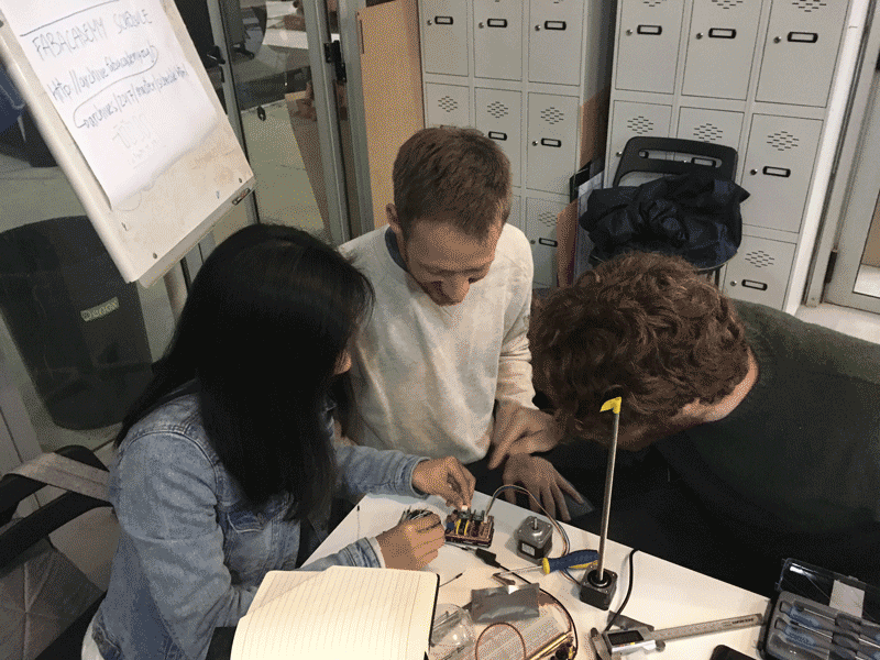
6. Job distributions
Mobile Holder and Gears: Paul
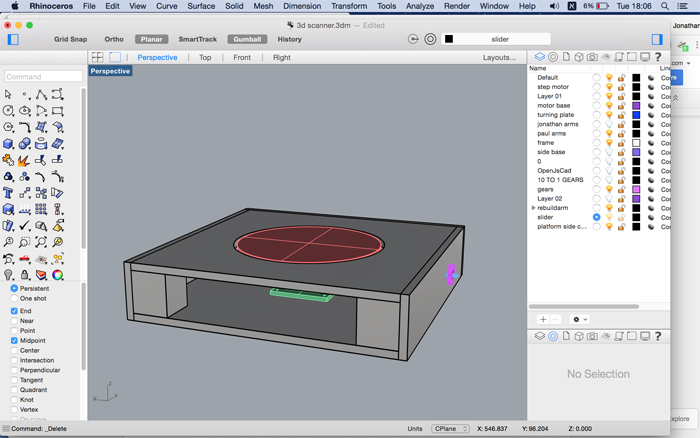
Platform: Jonathan
Motor holder and Gears: Javier
Slider, arm and conections: Ruby
Programming: Joan
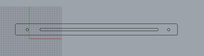
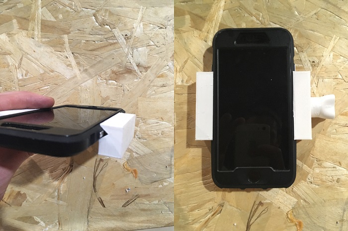
I am responsible for making the slider for mobile holder and its connection with the arm.
For the slider, there are two options at the beginning. One is to make a belt with holes, so that the position of the mobile holder can change by screwing the right holes. While the other options is to make a horizontal hole, so that the screw can simply slide horizontally and fixed in the position by tighting the screw.
At the end, the second option is chosen, as it enables more flexibility for the position adjustments.
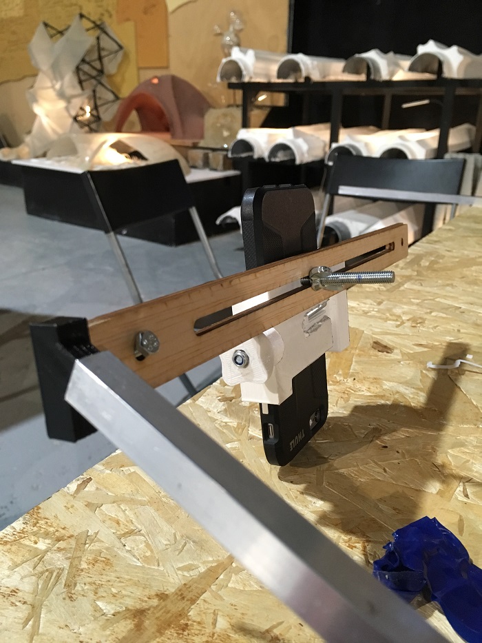
For the corner, there are also two options at first. One is to make a triangle-like structure and put screw on two ends in order to connect with the slider and the arm. While the second option is not by using any screw for the joint.
At the end, the second option is chosen, as screw is not require and more convenient for assembly. However, the connection printed by 3D printer is needed only when the wooden slider is connected with the arm made of steel. At the end, since the arm which is made of wood is used instead, therefore, the 3D printed connection is not needed. A press-fit connection between the slider and the arm is used.