Ruby Sun
Fab academy 2017
Week 4: Electronic production
Learning outcomes
A. Making the chip using roland mill
B. Soldering
C. Testings
D. Programming
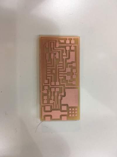
A. Making the chip
Firstly, i downloaded the chip with traces and interior for milling.( Traces , Interior)
Then, go to 'fabmodules.org'for the setting and prepare for the milling.
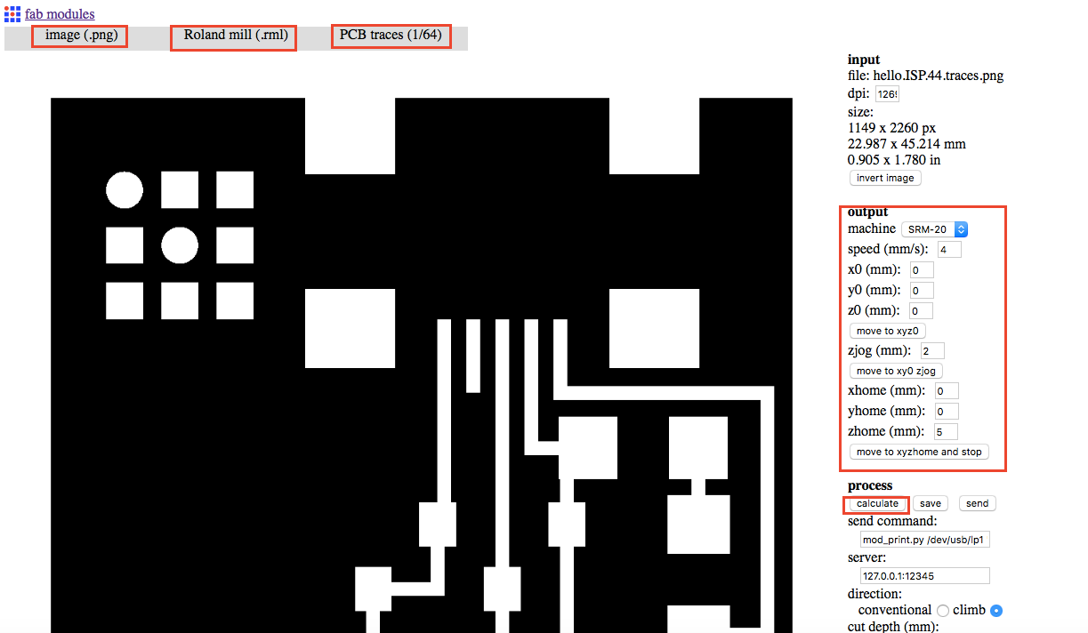
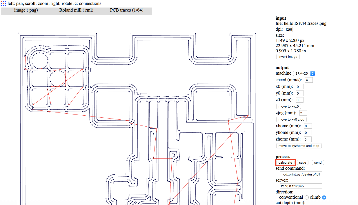
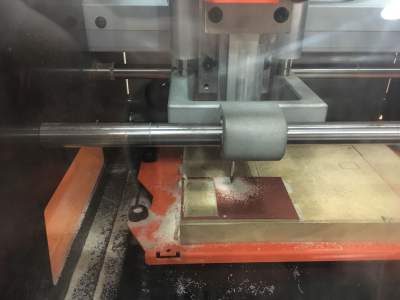
After preparing the traces of the circuit, repeat the same procedure for the outline, the only difference is to choose 'PCB outline(1/32)' instead of 'PCB traces (1/64)'. After preparing both files (.rml), i start milling by using the Roland mill.
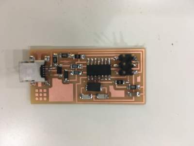
B. Soldering
Before soldering, grab all the components needed as below.
1. 1 Attiny 44 microcontroller
2. 1 Capacitor 1uF
3. 2 Capacitor 10pF
4. 2 Resistor 100 ohm
5. 1 Resistor 499ohm
6. 1 Resistor 1kohm
7. 1 Resistor 10k
8. 1 6 pin header
9. 1 USB Connector
10. 2 jumpers - 0 ohm resistors
11. 1 Crystal 20MHz
12. two Zener Diode 3.3V
13. 1 USB mini cable
14. 1 ribbon cable
15. 2 6-pin connectors
Solder the components accoording to the instructed chip. At first, when i finished all the soldering and tried the testing, there were something wrong that my chip cannot be programmed. Even though i tried to amend most of the soldering part, it was not working. At the end, i changed the microcontroller to make it work.
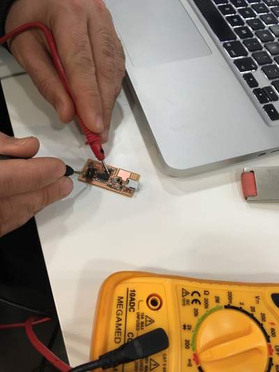
C. Testings
Voltage test
It is used to check whether it is well connected. If it is, a 'beep' is heard.
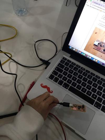
Smoke test
Connect the chip with the computer. As there are no error message saying that the board is drawing too much power, my board has passed the testing.
D. Programming
Firstly, after connecting the chip with the computer. Type 'cd Desktop/firmware' and 'cd Desktop/fabISP_mac.0.8.2_firmware'.
Afterwards, there are four steps as follow:
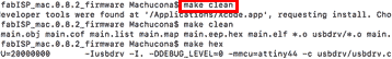
1.Make clean
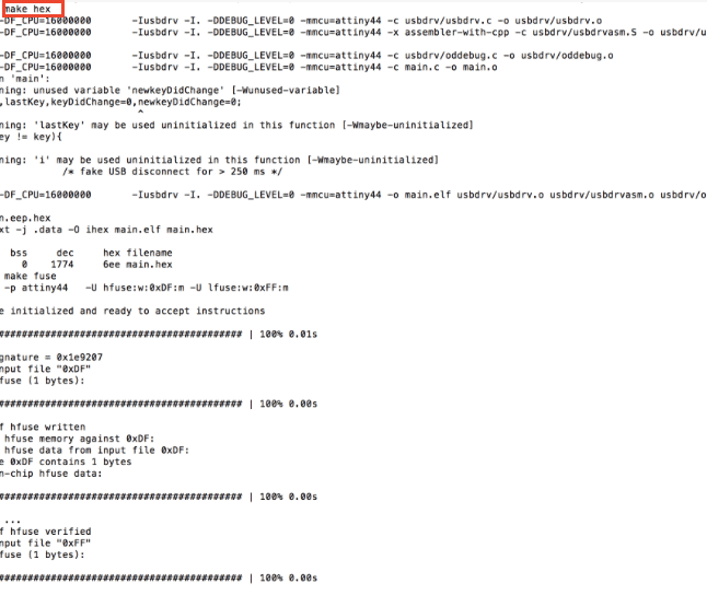
2.Make hex
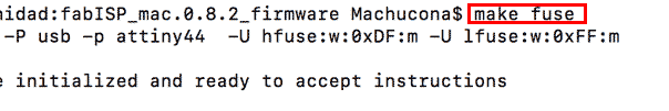
3.Make fuse
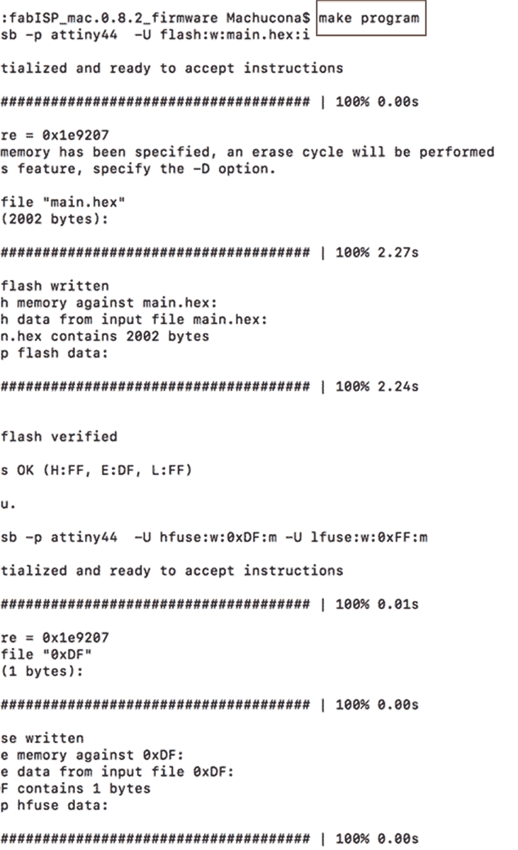
4.Make program
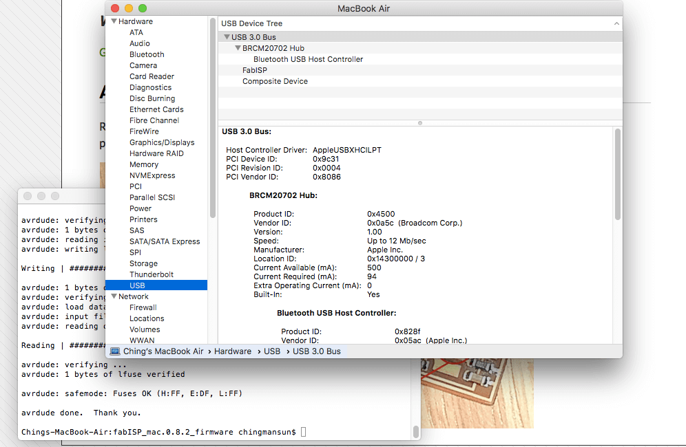
After making all the programming, the below screen is to checked that a USB is created.