Ruby Sun
Fab academy 2017
Week 15: Networking Communication
Learning outcomes
A. Understanding the workflow of network design
B. Making the Serial Asynchronous for knowing the foundation
A. The Bridge and the node boards
For the assignment, I will be making two different boards, one bridge and two nodes for the network communication.
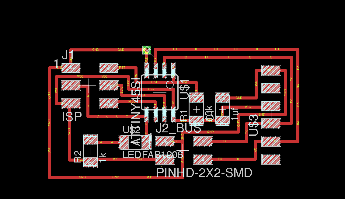
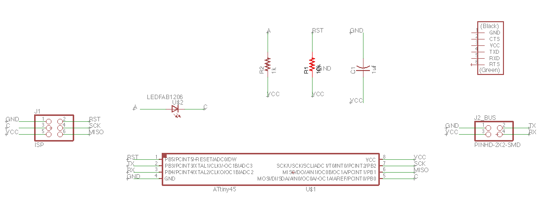
Brdige
1. Capacitor 1uf
2. Attiny45SI
3. AVRISPSMD/2X03SMD
4. LED
5. PINHD-2x2-SMD/2X02SMD
6. Resistor 10K
7. Resistro 1K
8. FTDI-SMD-Header/1x06SMD
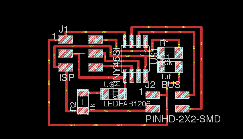
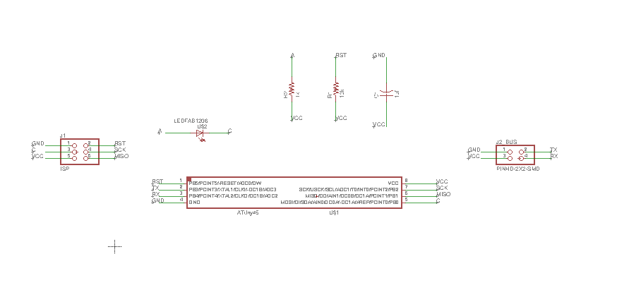
Node
1. Capacitor 1uf
2. Attiny45SI
3. AVRISPSMD/2X03SMD
4. LED
5. PINHD-2x2-SMD/2X02SMD
6. Resistor 10K
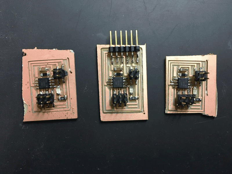
Below are the three boards, one bridge and two nodes.
Programming
1. Program each board separately (program the bridge first, followed by nodes)
2.Downloaded the files from Fab Academy and stored in one place
3. Go to terminal, located it to the folders where the files are saved
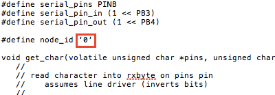
4. Open the c file, keep the node_id number to 0.
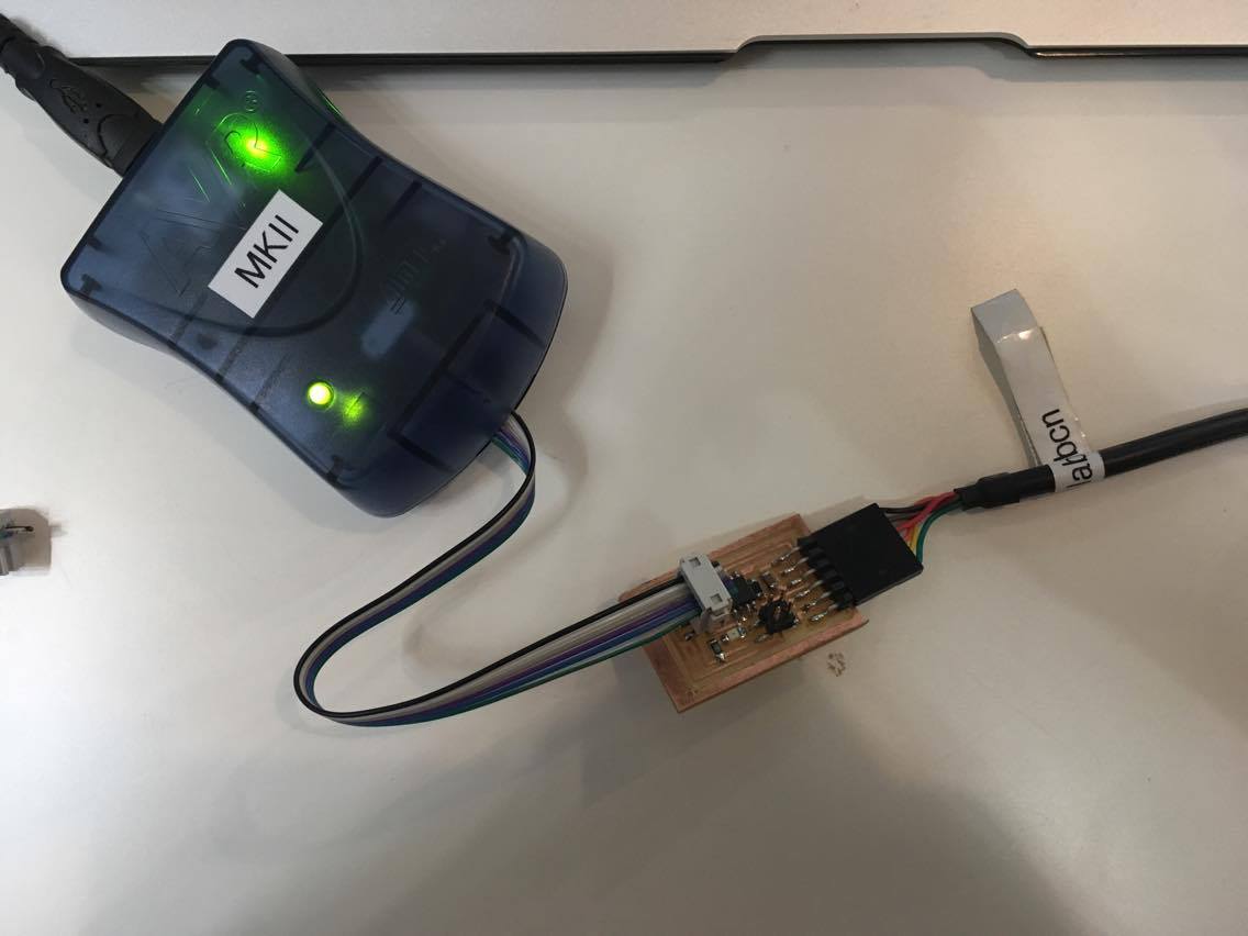
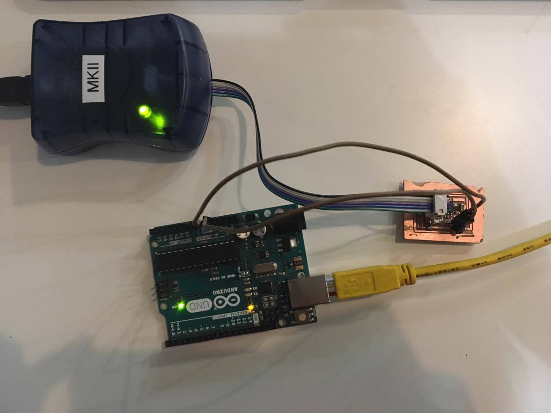
5. Connect the bridge board as follows.
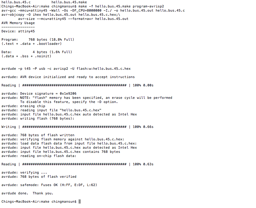
6. Make sure the node number for the bridge is 0, and now can type the following commands for MAKE FILE
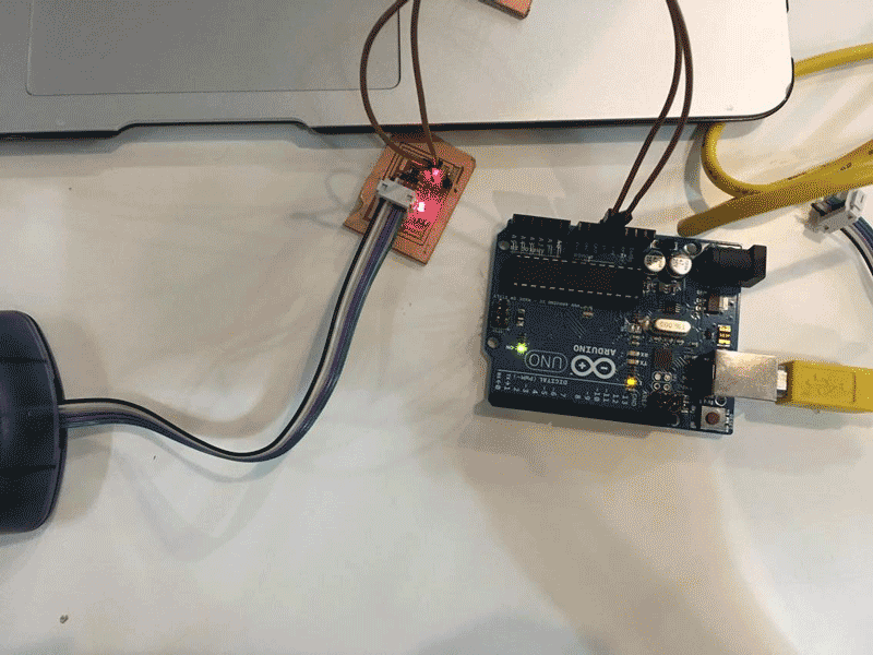
For programming the nodes, since there are no FTDI cable, other way of power supply is needed.
1.connect the board with arduino
2. connect 5V(arduino) to V(node board) with a jumper
3. connect Ground(arduino) to the GND(node board)
After getting the connection, repeat the same process as before, but just change the node number to 1 for the first node, change to 2 for the second node.

After programming each board separately,it's time to connect them together.
1. Go to Arduino and open any file
2. Open serial monitor
3. Type 0 ,1 ,2 and send
Firstly, I typed '0' and the bridge and one of the node which programmed for node id zero blinks. Then I typed 1, since I did not program for node id 1, all the three boards light up at the same time. Then I typed 2, one of the node blinks.
Please press the link for downloading.