Ruby Sun
Fab academy 2017
Week 13: Input devices
Learning outcomes
A. Using Adrunio for setting up the Capacitive sensor
B. Programming for the capacitive sensor
C. Using Eagle to design the board
D. Milling and soldering
E. Programming
A. Using Adrunio for setting up the Capacitive sensor
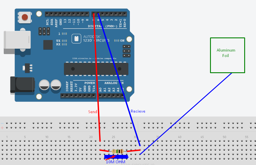
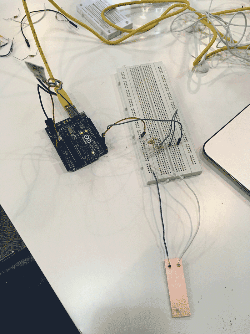
1. Connect one wire for the sensor pin and one wire for the receive pin
2. In between the two wires, put 10M ohm resistors
3. Connect the other end of the resistor( the end near to the receive wire) with the copper plate, which acts as a capacitive sensor.
The diagram below shows a clear illustration of the connection.
B. Programming for the capacitive sensor
1. Change the pin number to 4 and 2 (pin 2 is sensor pin).
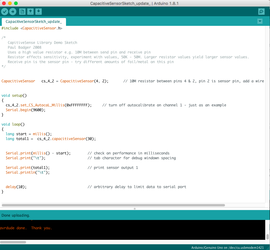
2. the serial monitor will show the changes in number. When I press the copper plate, the number will increase quickly. The video below shows the effect of the capacitive senor.
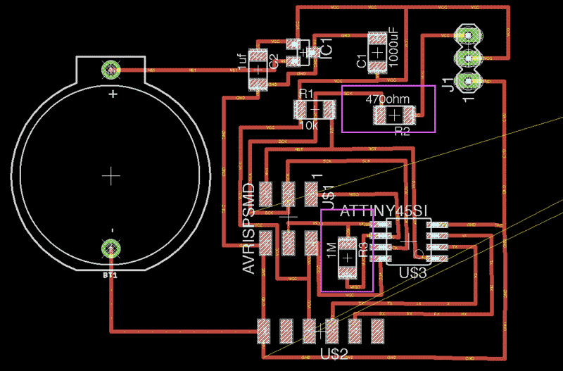
C. Using the Eagle to design the board
Because of the final project, I have combined the capacitive sensor with the LED in the board.
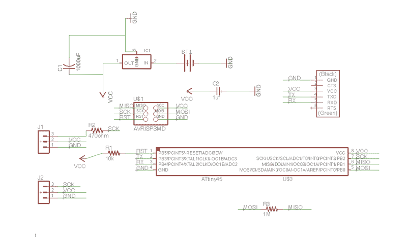
Here is the list of components:
1) Attiny 85
2) AVRISPSMD
3) Regulator 5V 0.1A
4) Capacitor 1000uf
5) Capacitor 1uf
6) Six-pin header
7) One battery holder
8) Resistor 1M ohm
9) Resistor 470 ohm
10) Three-pin header
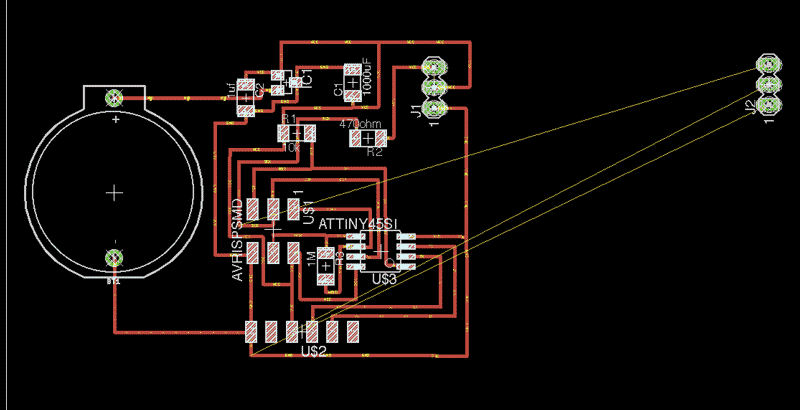
In the schematics, the resistors of 1M ohm is connected between the MOSI and MISO.That is for the connection of the capacitive sensor. While the LED strip will be connected to the SCK of the AVRISPSMD through the Resistor of 470 ohm. They are indicated in pink.
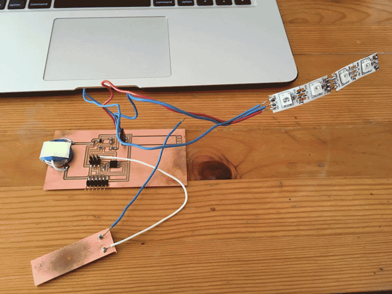
D. Milling and Soldering
After completing the circuit, here comes the milling, soldering parts.
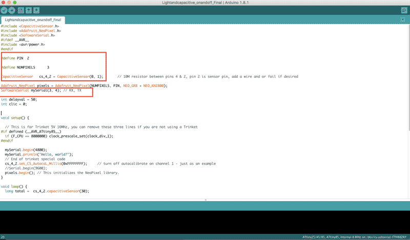
E. Programming
After making the board, the coding will have to adjust as the pin number of the arduino is different from the connection in the circuit board and here is the Attiny 85 pinout.
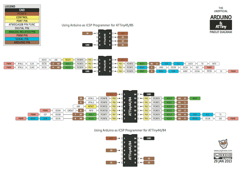
For the capacitive sensor, as it is connected with MOSI and MiSO, so that is pin 0, 1. For the TX and RX, since the pin is 2,3, therefore it's pin 3,4 for the coding.
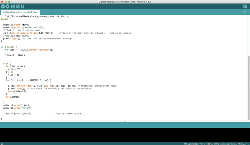
Below shows how the capacitive sensor works with the LED strip.
Please click here for downloading.