INPUT-ING
The objective of this assignment is to Add an input device to a microcontroller board you’ve designed and program it to do something. And to demonstrate workflows used in circuit board design and fabrication to implement and interpret programming protocols.
Requirments:
// Described your design and fabrication process using words/images/screenshots.// Explained the programming process/es you used and how the microcontroller datasheet helped you.
// Outlined problems and how you fixed them
// Included original design files and code
Experience
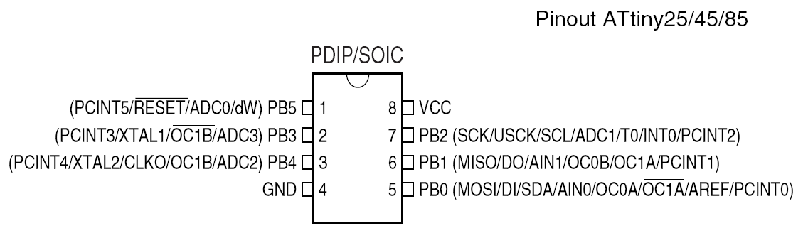
About ATtiny45:
The high-performance, low-power Microchip 8-bit AVR RISC-based microcontroller combines 4KB ISP flash memory, 256-Byte EEPROM, 256B SRAM, 6 general purpose I/O lines, 32 general purpose working registers, one 8-bit timer/counter with compare modes, one 8-bit high speed timer/counter, USI, internal and external Interrupts, 4-channel 10-bit A/D converter, programmable watchdog timer with internal oscillator, three software selectable power saving modes, and debugWIRE for on-chip debugging. The device achieves a throughput of 20 MIPS at 20 MHz and operates between 2.7-5.5 volts.
By executing powerful instructions in a single clock cycle, the device achieves throughputs approaching 1 MIPS per MHz, balancing power consumption and processing speed.
sideNote
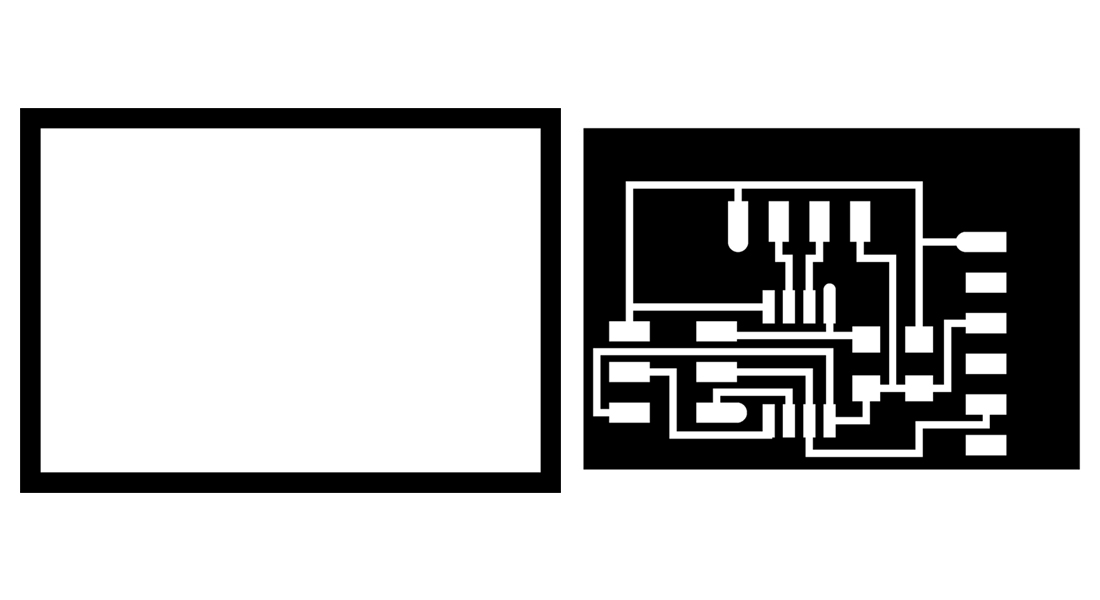
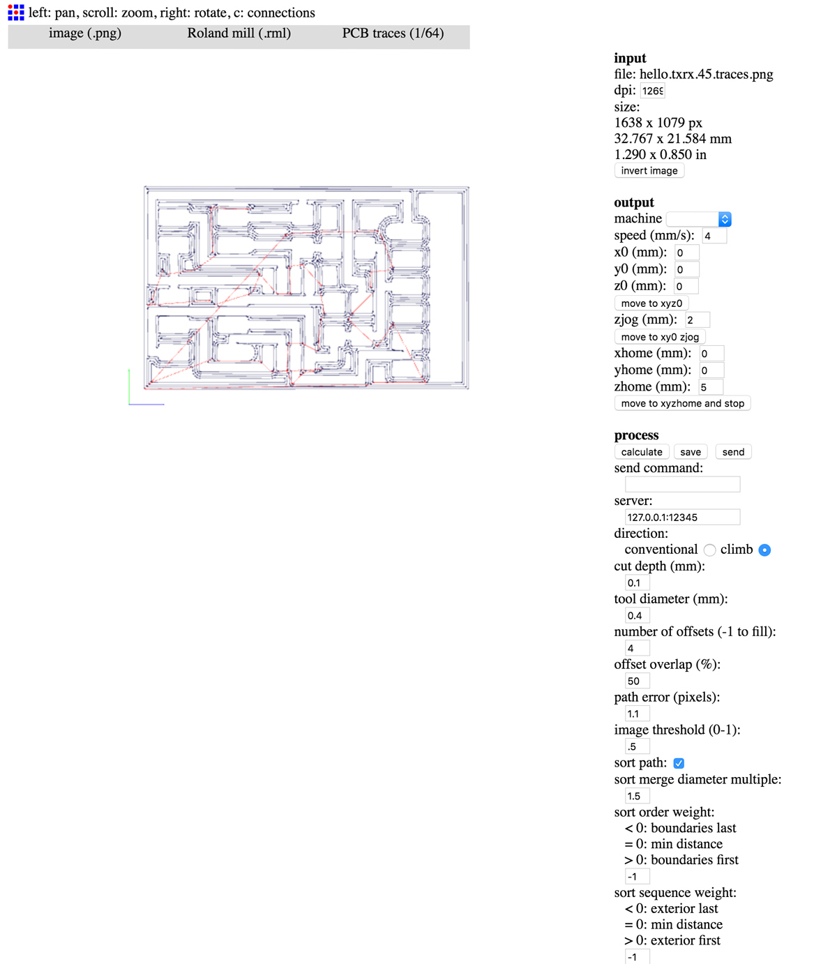
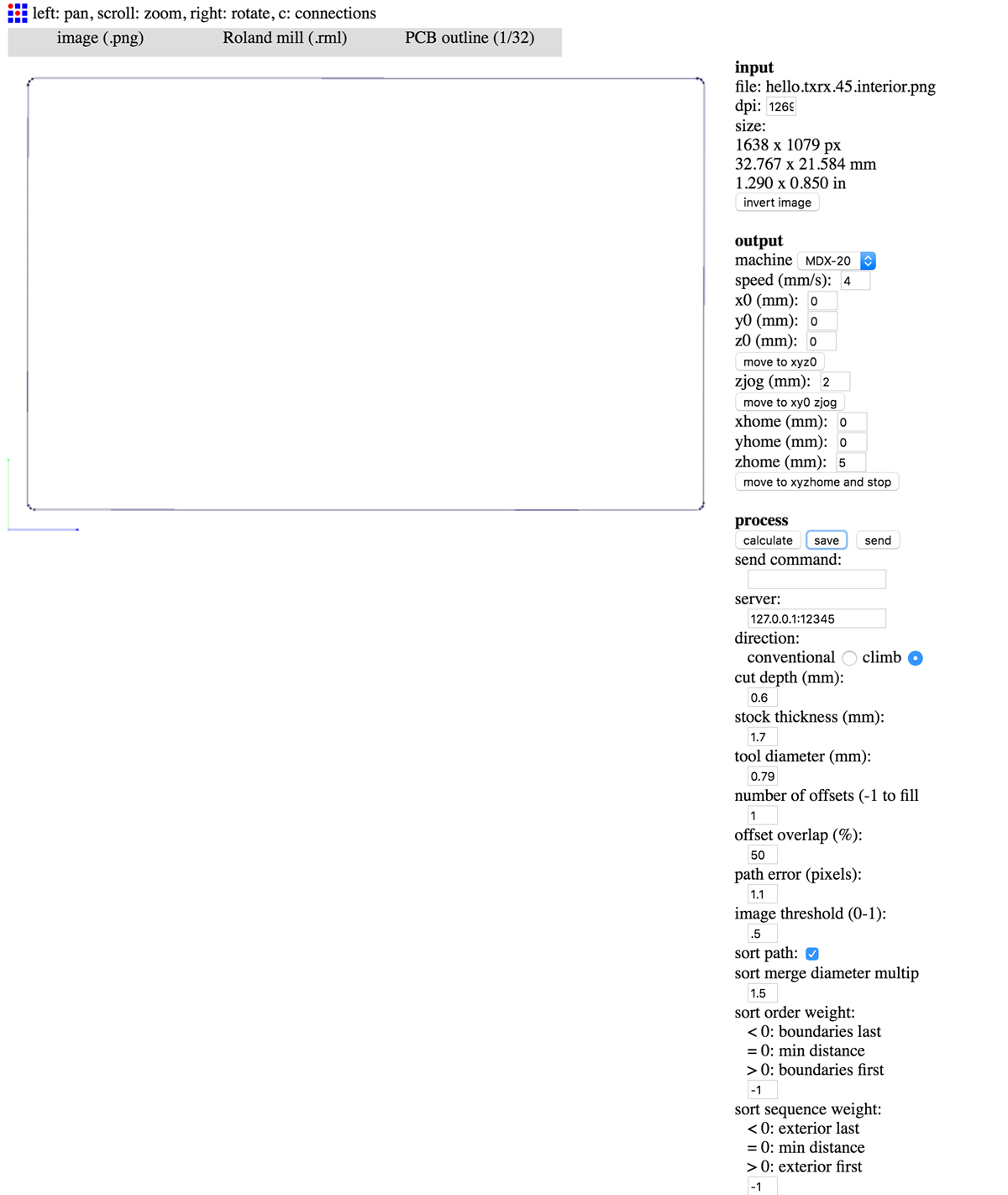
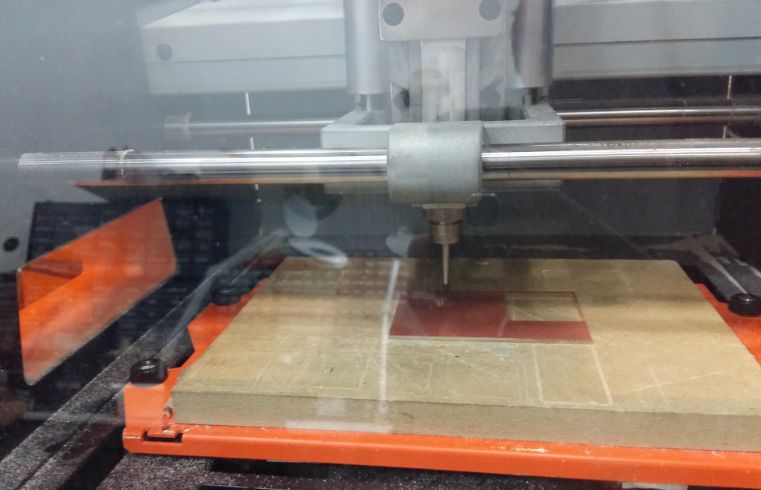
went through the process of milling and soldering as shown in previous weeks . First placing the 64 bit mill and sending the .rml to the machine.
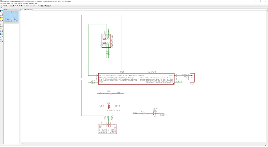
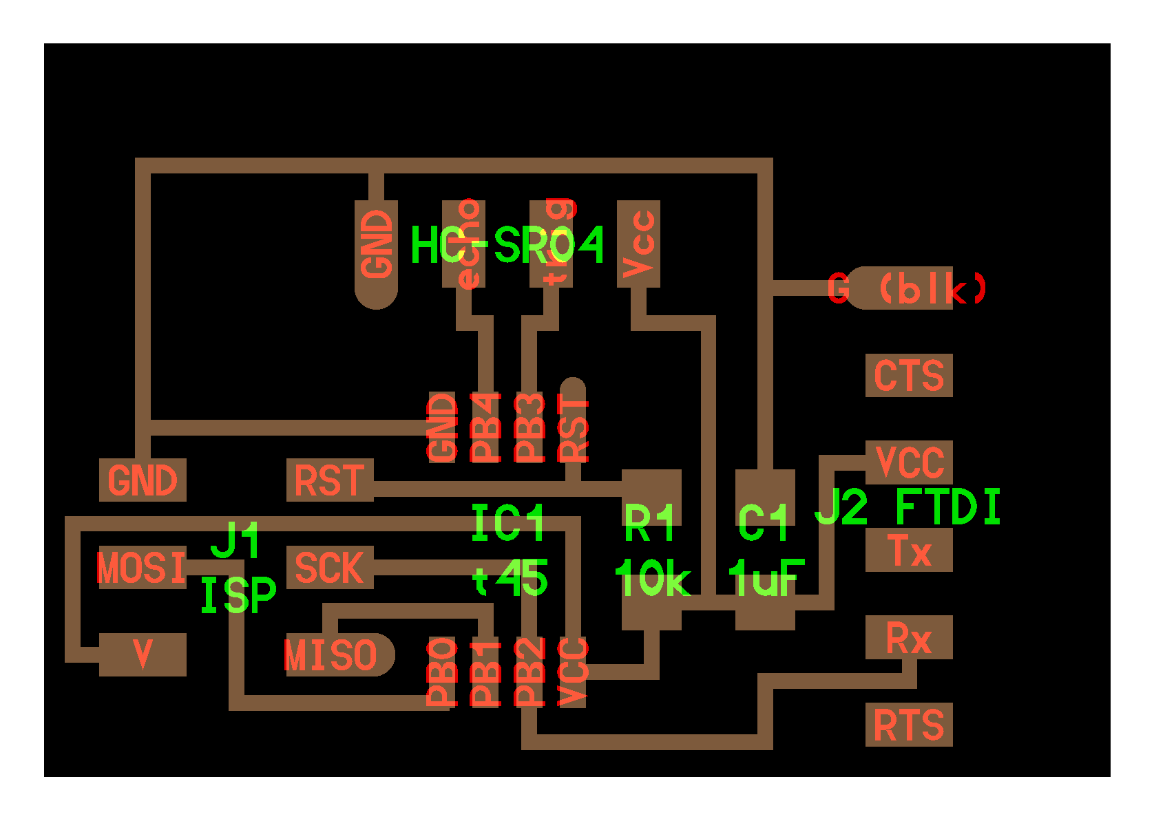
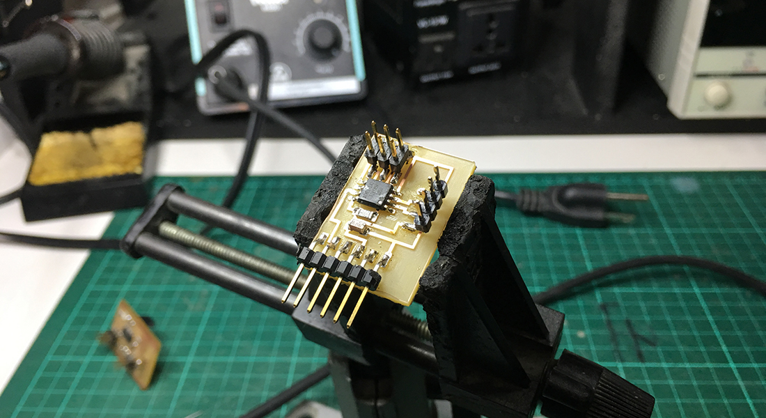
// AT tiny 45 Microcontroller
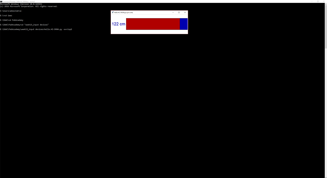
// HC-SR04 Sonar sensor
// FTDI Header
// R1 Resistor 10 kilo ohms
// R2 Resistor 499 ohms
// LED
// ISP Header 2 by 3
// C1 Capacitor 1 Micro Farad
// Programming the board:
a. connect computer to Attiny via mini usb; connect Attiny to new sensor board via ISP cable and connect sensor board via FTDI connection to computer.
b. save .make and .py files in folder on computer; find those files through the Terminal (via commands 'cd') and type "make -f hello.load.45.make program-usbtiny"
c. Type command " make -f hello.load.45.make program-usbtiny" in Terminal
|Python interface:
1. Download Python
2. Once downloaded; make sure that the source folder appears on 'Environment variable' (otherwise it will not appear on the command line)
3. Install pip so that you could easily install pyserial and Tkinter modules. ( you will probably get an error and can easily be changed again by linking into environment variables)
4.As you are using version 3 open the .py files from Neil in text editor (like sublime or atom) and change 'Tkinter import' to 'tkinter import' and 'print "Hello world" to 'print ("Hello world")
5. Install python-tk
6. In downloaded .py folder on command line type " python hello.txrx.45.py COM5" and interface should pop up. Note: COM depends on number in device manager
I uploaded the C-code provided by Prof. Neil on Attiny45 which was worked like charm however I was not able to recieve data on the terminal. However I faced dificulty in interfacing the python-code provided by Prof. Niel to interface with computer through serial port. It seems the primary resaon for that is difference in Python versions. The code is written for version 2.7 Python while I am using the latest the version (i.e. 3.6). Although there are several IDEs available for coding and debugging python code but I prefer to use python terminal Idle which is simplistic and yet provides sufficient debug information.
I have experimented with Neil's code because i might use it for my final project as i am planning to have installed approximate sensors to the mini robots and to keep a distance between them.