PROGRAM-IT
The objective of this assignment is to program the board we have designed for week06 . Read the microcontroller data sheet and program he board to do something, with as many different programming languages and programming environments as possible and omplement programming protocols.
Requirments:
// Documented what you learned from reading a microcontroller datasheet.// What questions do you have? What would you like to learn more about?
// Programmed your board.
// Described the programming process/es you used
// Included your code.
Released: 15.03.2017
Week08: embedded programming
References:
// Computer applications resources
// Programming ATtiny with Arduino
Experience
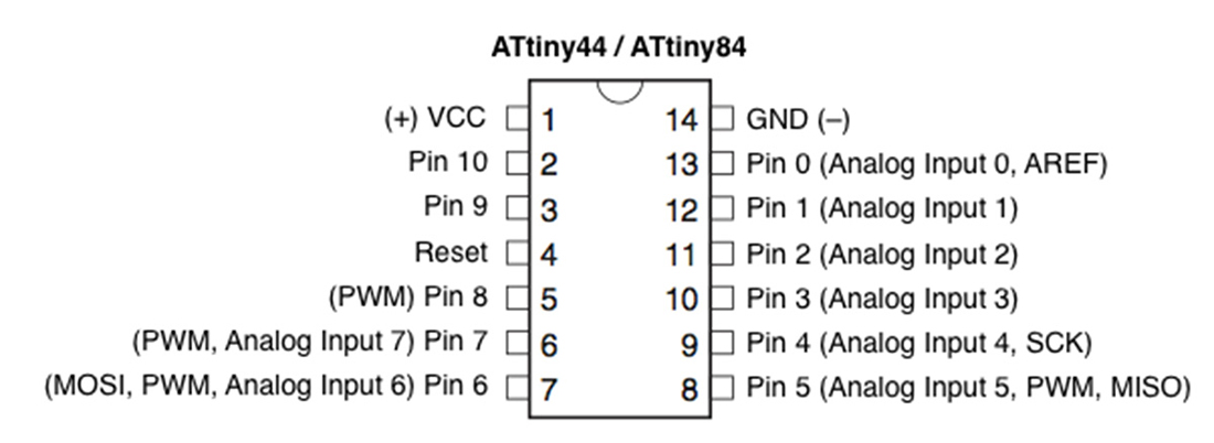
About ATtiny44A:
1) It is a chip with 14 pins; including VCC and GND
2) Port B (PB3:PB0) is a 4-bit bi-directional I/O port with internal pull-up resistors
3) RESET (PB3) A low level on this pin for longer than the minimum pulse length will generate a reset 4) Port A (PA7:PA0) is a 8-bit bi-directional I/O port with internal pull-up resistors
4) Port A has alternate functions as analog inputs for the ADC, analog comparator, timer/counter, SPI and pin change interrupt
5) CPU(central processing unit) ensures correct program execution by accessing memories, performing calculations, controlling peripherals, and handling interrupts
6) it has three types of memory Flash stores the compiled program even when the power is off
7) SRAM saves temporarily variables while calculating
8) EEPROM is for data storage
9) ATtiny44A features successive approximation Analog-to-Digital Converter (ADC). It generates a 10-bit result which is presented in the ADC Data Registers, ADCH and ADCL. ADCL presents only the low byte of the ADC conversion result and ADCH presents only the high byte. ADCL is read first, then ADCH. When ADCH is read, ADC access to the ADCH and ADCL Registers is re-enabled and a new result is provided.
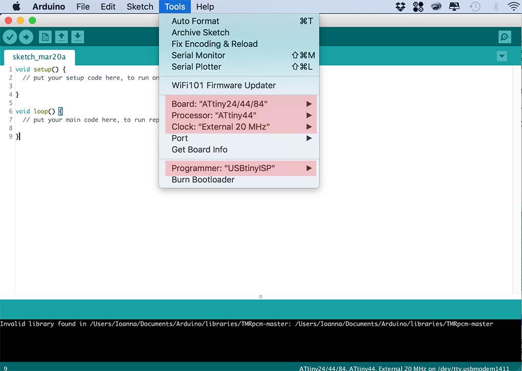
I have programed it with Arduino, but what you have to di is to download the attiny library to make it happen.
Go to Tool---- Board---- and change it to 'Attiny and the Processor to 'Attiny44' and the clock to 20MHZ .
*NOTE*
To connect the the Helloboard to the Attiny, It is important to know where the GND is to connect them together.The Attiny has a mini usb connector for power; and the Hello board has an FTDI connection which connects via usb to the computer.
Programming with Arduino IDE
Here are the necessary settings on the Arduino IDE to be able to program the atTiny with the fabISP.
The board must be connected to the ISP and the ISP to the computer, and to a power supply with the FTDI header, I burnt the bootloader, and uploaded the first Arduino sketch which turns on and off the LED depending on the input from the button.
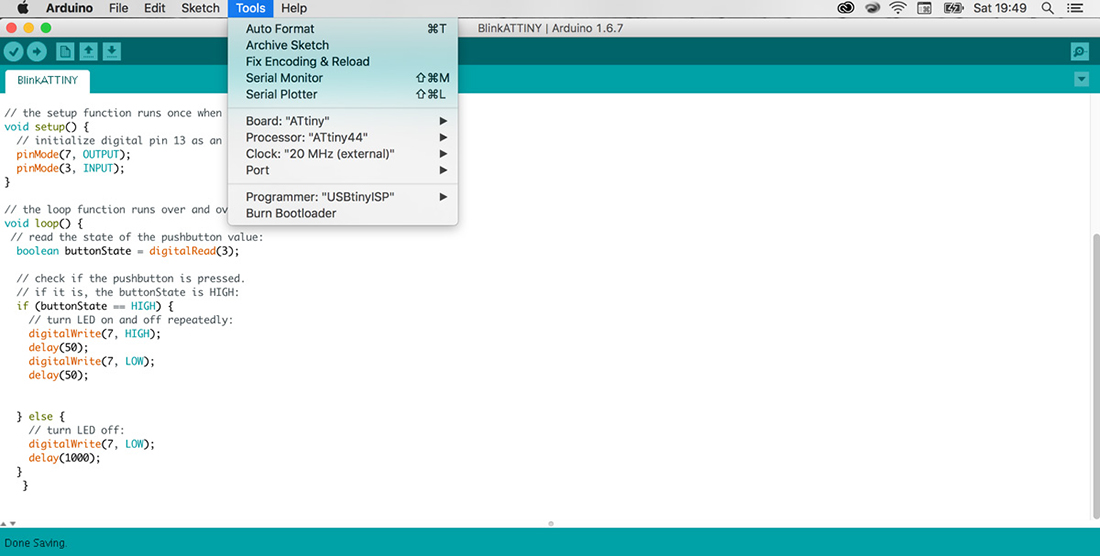
I started manipulating the code and i made it kind of the opposit of what it is, so when i push the button and keep pushing it stops and when i release it starts blinking like crazy.
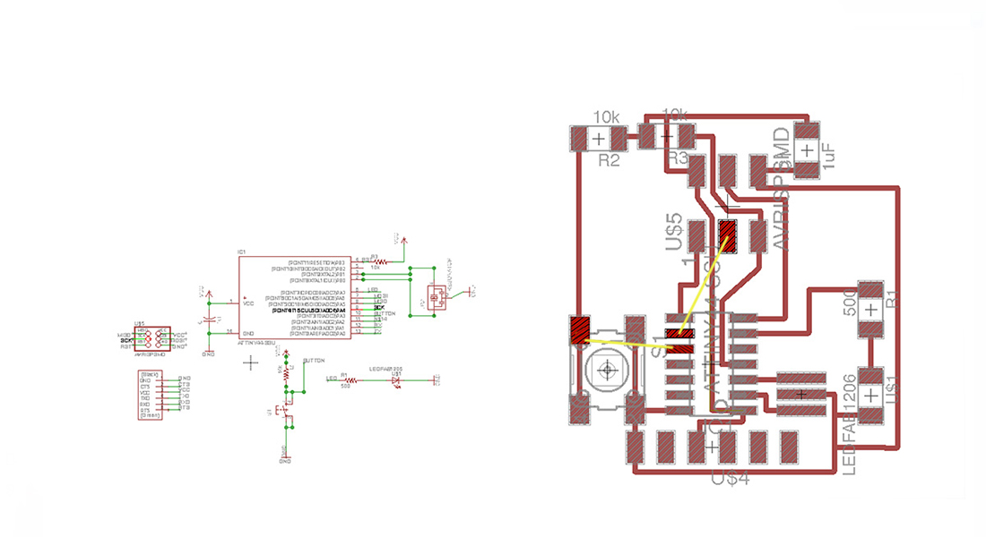
When making the Helloboard i found some missing connections which needed to be corrected in eagle schematics. 1. Button; being a digital input would need to be connected to the micro-controller to program via arduino. 2. SCK in the ISP needed to be connected to pa 4/pin 9 on the micro-controller. See hello.ftdi.44 . This was corrected using external wires and still worked in the end!