03 - computer controlled cutting
This week was about computer controlled cutting. The two machines I will be discussing are the vinyl cutter and the laser cutter, both have a fairly similar process as they both operate in 2D, but with very different results and capabilities. I will discuss the design process to prepare files for both machines as well as give a short conclusion at the end. The files are available to download at the bottom of this page.
First up is the vinyl cutter, at Fab Lab Amsterdam we have a Roland GS-24. I used this machine to make laptop stickers for an upcoming event about IoT that I am organizing.
SOFTWARE USED:
Inkscape
Adobe Illustrator + Roland driver
STEP 1 - making a vector image
I have a logo which I got from the designer as a PNG, a very standard file type for images, but this can not be read by either a vinyl cutter or a laser cutter because these machines require a vector image.
In Inkscape I did the following:
1 - import -> import your image
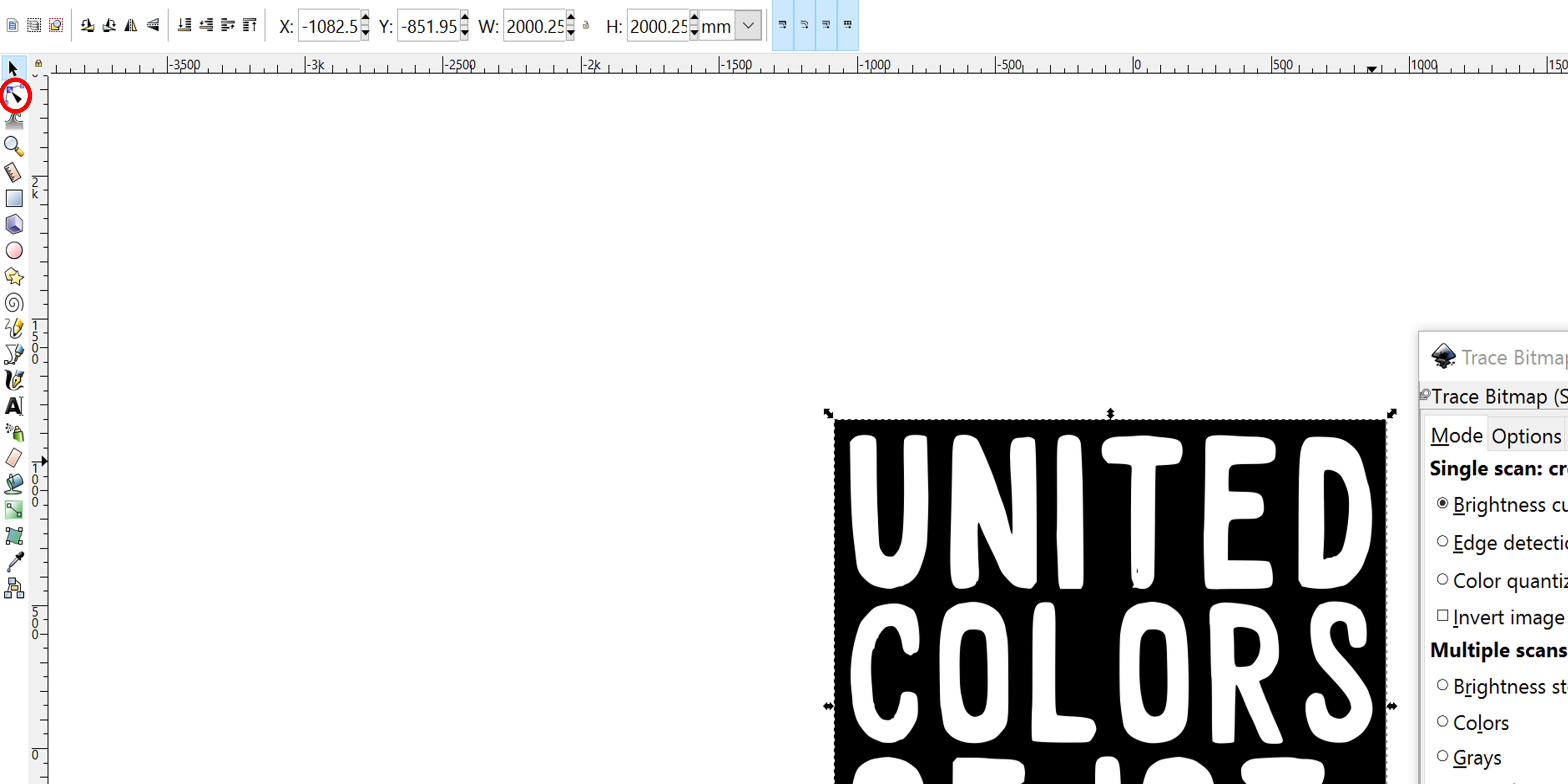
2 - go to path -> trace bitmap
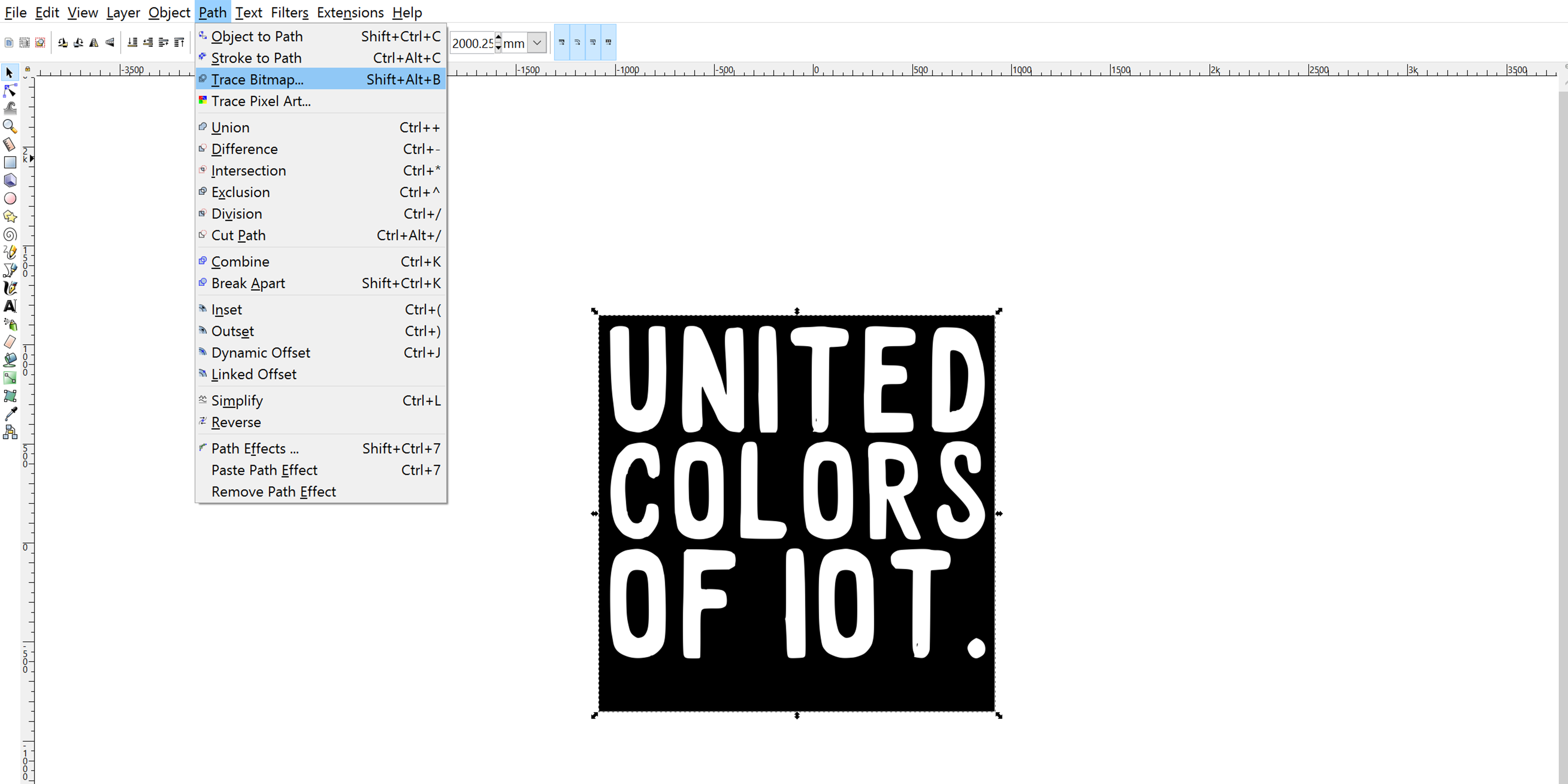
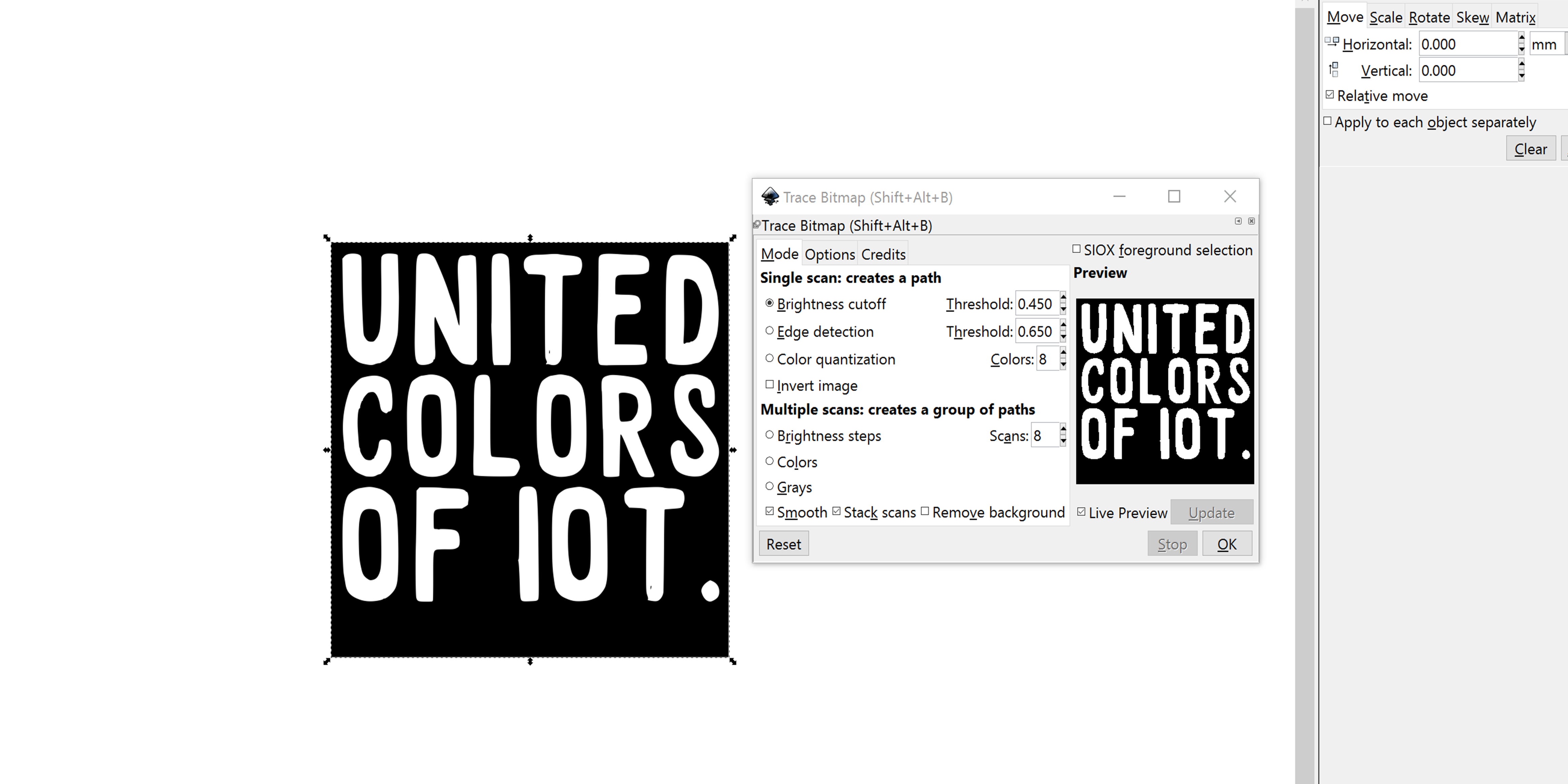
3 - turn on the Live Preview function to see if your image can be traced. In this case it’s a black and white logo which makes tracing very easy, but if you have a more detailed image you might want to play with the settings and the live preview comes in handy.
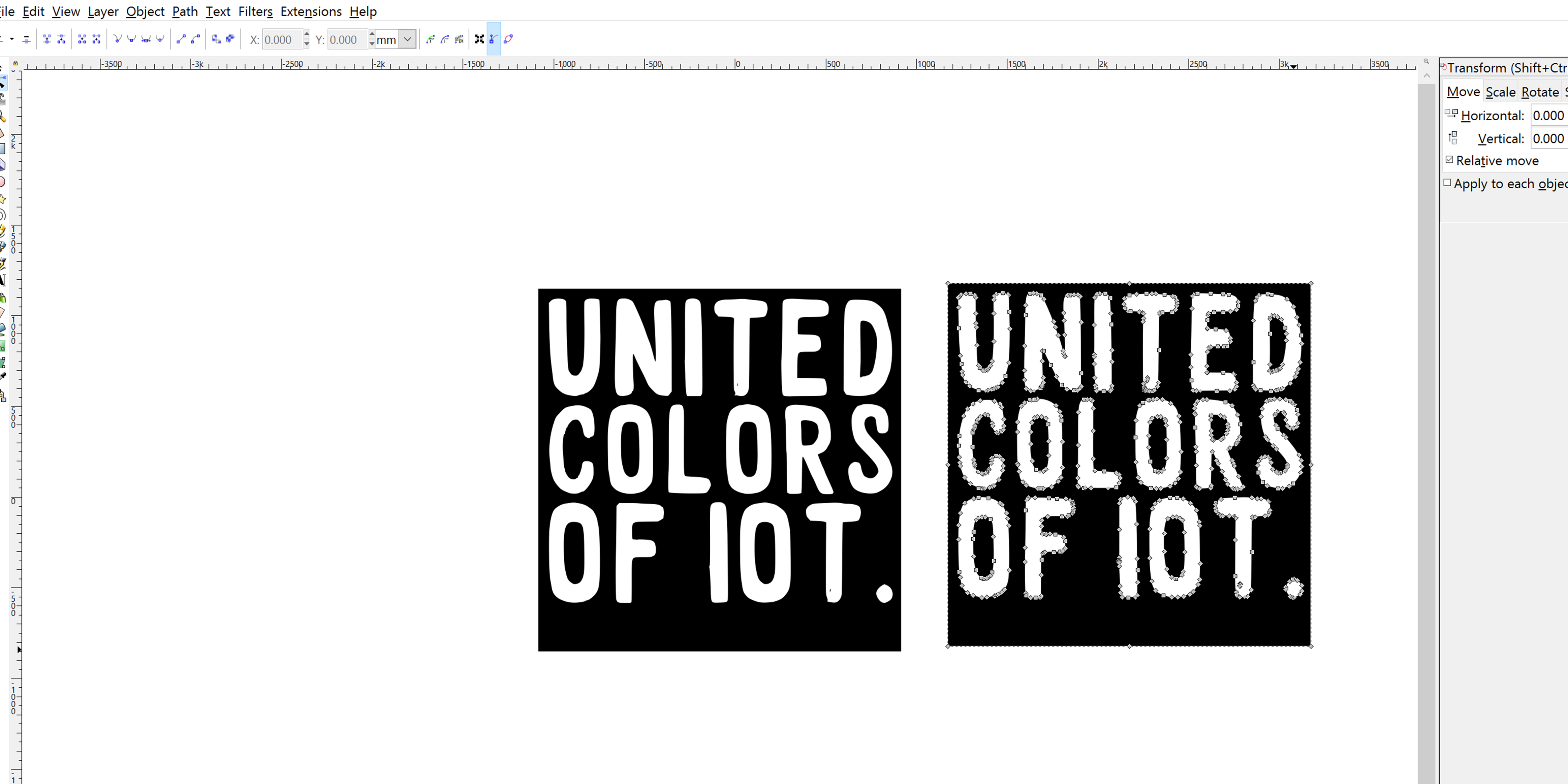
4 - once you have your vector you can delete the PNG from the view as we will now only use the vector. You can recognize which one is the vector by selecting the vector tool and hovering over the images. The vector will show a series of points along the lines of the image.
5 - the vector needs some changes to make it readable for the vinyl cutter, an image should never have fill and the line stroke should be 0.001mm. To do this, go to Object -> fill and stroke
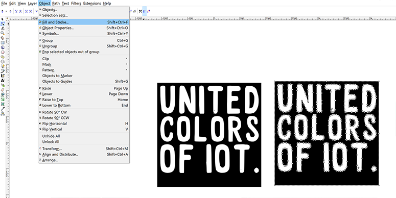
6 - in fill, select the cross indicating there is no fill, in stroke, select the first square indicating one color, and slide the R color bar all the way to the right to show 255. This means the lines will be one solid color.
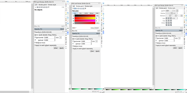
In the stroke style tab, choose 0.001 to be the width of the line.
7 - now you’re all done and ready to go, just save the image as a DXF file and transfer it to the computer you’re going to use for the vinyl cutter.
STEP 2 - setting up the machine
Before setting up the file in Illustrator, set up your machine. In my case because I used a large roll of vinyl sticker material this is what I did:
1 - Load material, lift the handle at the back of the machine, insert the material, adjust the wheels to be under a white line and lock the material in place.
2 - In the on-screen menu select ‘roll’.
3 - In the menu set the force of the pen to 80, set the manual slider at the front of the machine to 0. These are settings that are known for our machine to work with the current material, but you should always test this and find your own settings of course!
4 - Hit the test button to make a little test on the material to see if you’ve got the right settings.
STEP 3 - setting up the file in Illustrator
For the computer to communicate with the cutter, a driver is necessary. Assuming your lab has a dedicated computer for your machine I will only talk about the steps taken in Illustrator with the driver installed.
1 - Open you DXF file in Illustrator and scale if needed using ‘transform’.
2 - Go to file -> print
3 - Select the vinyl cutter and hit ‘preferences’
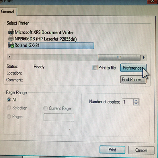
4 - Click ‘Setup’
5 - In the cutting area window, click ‘get from machine’
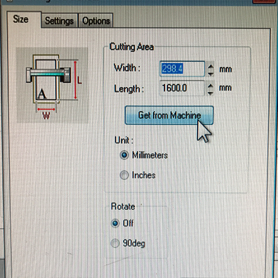
6 - now hit print, and again hit print in the next window and your machine is off to cut!
STEP 4 - making the sticker
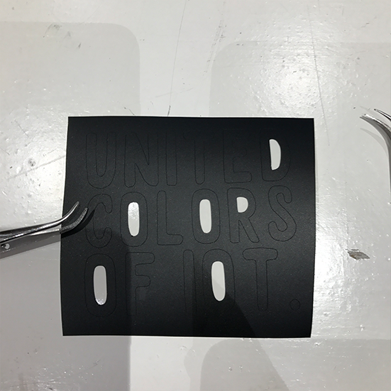
The first observation after cutting the logo a few times is that there is a more limited work area than I thought, resulting in the last sticker to be not fully cut.
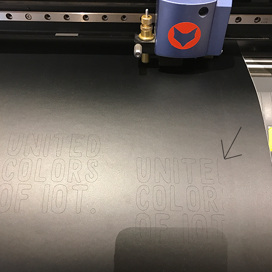
This is because the knife is on the left side of the moving head making it not reach the full width of the cutting area. Once the cuts are made you have a few final steps to take before the sticker can shine on a laptop.
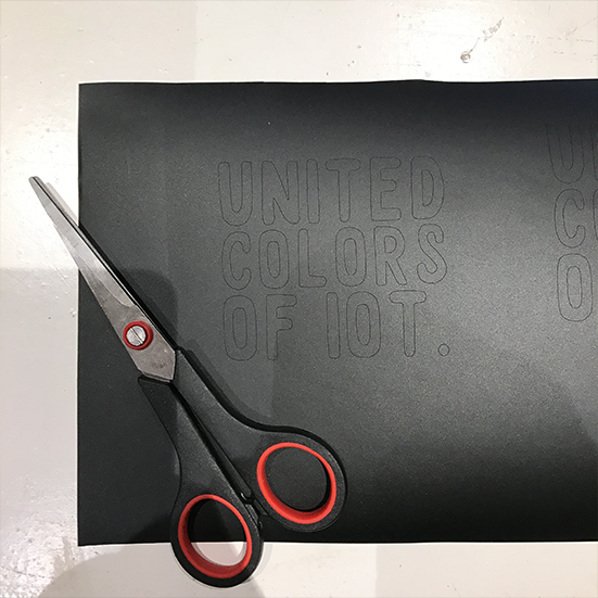
1 - Cut out squares with some room around the letters
2 - Peel away letter infill, like from the letters D and O. Do this using sharp nosed tweezers or other sharp, pointy tools.
3 - Peel off the background
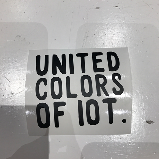
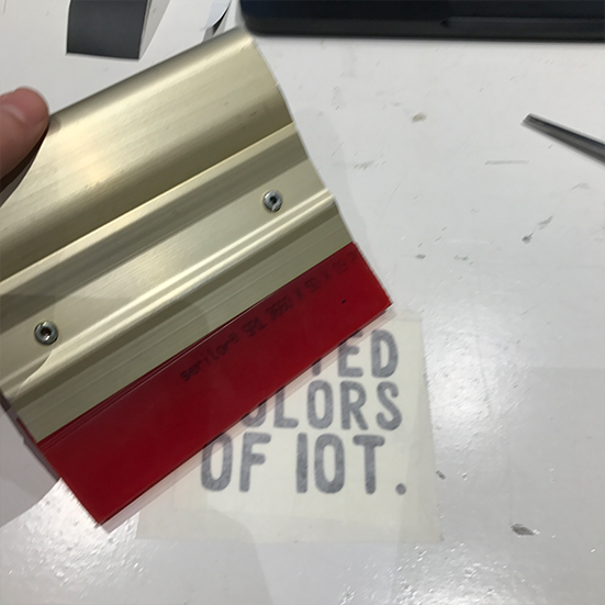
4 - Overlay the sticker with transfer paper and smooth out using a rubber wiper or apply manual force.
5 - Find a nice shiny laptop to stick it on!

LASER CUTTING
To get to know the laser cutter and designing for the laser cutter I focussed on two aspects, first of all the cutting loss, or kerf for various materials, and second of all how to design a press fit construction.
KERF TESTS
When the laser beam hits the material, the material either burns, melts or evaporates, leaving (a small) space between the two parts. For the group assignment we wanted to investigate how much loss there is with various material and if we could find some kind of correlation. Because the kerf can be very small, we cut ten pieces out of a material, meaning we have eleven cut lines, and added it all op. This makes it easier and more precise to measure the kerf, because you measure the cumulative kerf and then divide it by eleven.
We put the results in these graphics(thank you Blanca for making this in Photoshop):
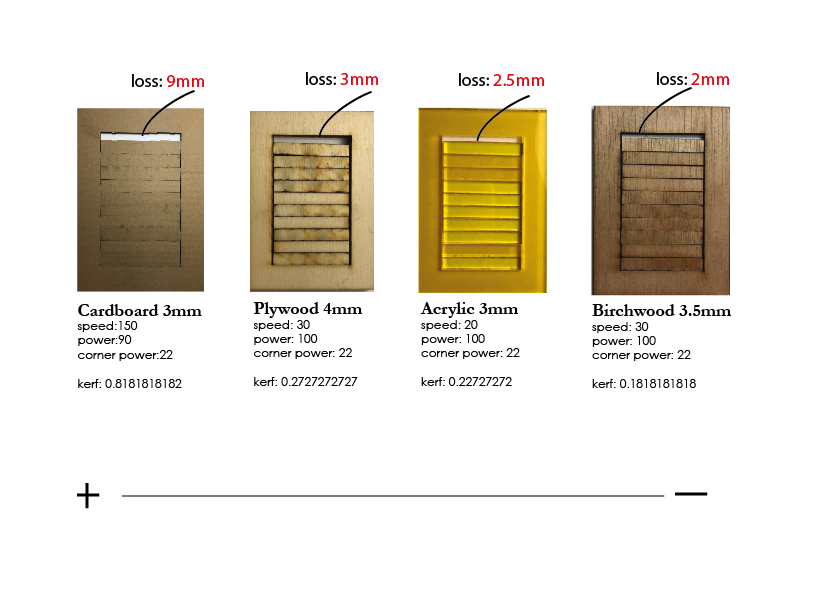
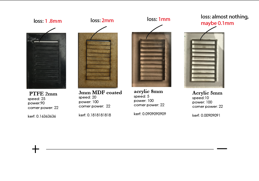
Conclusion:
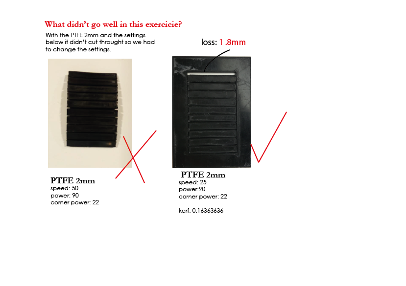
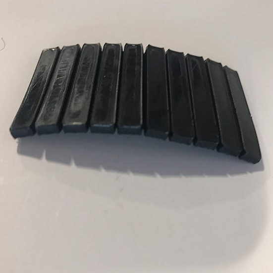
When it comes to acrylic, the thicker the material, the less kerf. For some reason we assumed it would be the other way around but we have the proof now. A nice surprise was a flexible PTFE material that didn’t cut all the way through which gave a flexible structure, could come in useful someday.
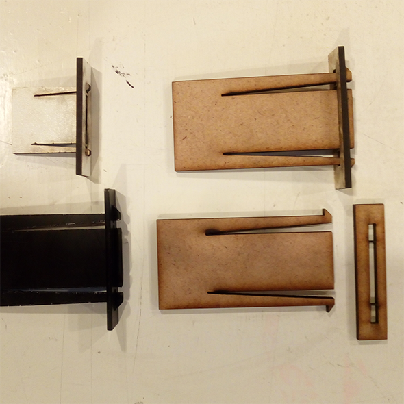
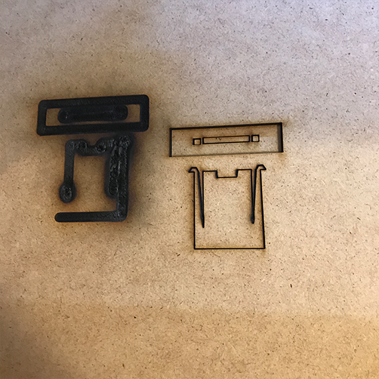
joint experiment
We also tried to make a clip style joint connection out of various material.
Although the basic construction worked we quickly discovered the design of the joint needs more work for it to be really efficient.
Surprisingly enough also very unflexible materials like MDF showed enough flexibility needed to be able to be pressed together to snap in the receiving end of the clip.
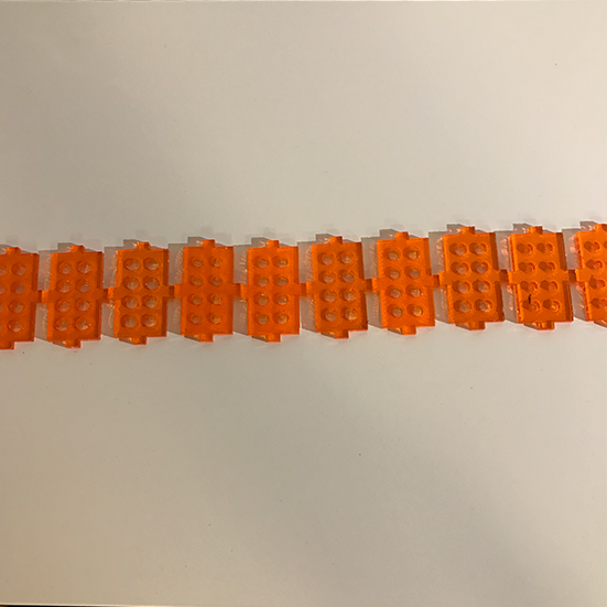
CONSTRUCTION KIT
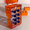
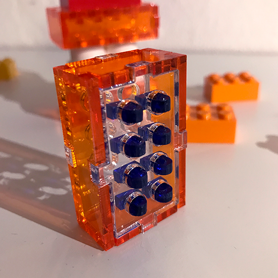
I made a construction kit that combines laser cut acrylic with LEGO, as an exploration for my final project. The pieces in the kit can either be assembled together or with LEGO or both.
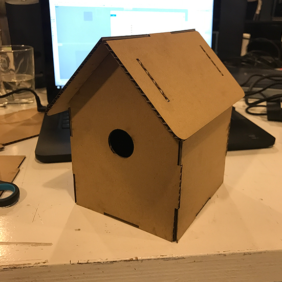
Before I did this however I misinterpreted the assignment and I made a parametric birdbox out of cardboard that can scale, adjust kerf etc. and still be snap fit no matter the material, but it’s not really a kit so I made the LEGO brick afterwards.
To make a parametric design I followed the same steps I did earlier in the computer aided design week, so I’m not going to do the step by step of parametric design in Fusion 360 again.
You can find the step by step for parametric design here. Instead I will only show the specific steps that differ from the previous week and that are specific for laser cutting.
design considerations
I wanted to design a kit that is both compatible with itself and with LEGO bricks, and I wanted the design to have as little unique components as possible.
That is why I designed a classic box with holes both in the top and the bottom. In the top part you snap the studs, or you leave them open if you want to female sides, or you can make to male sides. Remix it as you like.
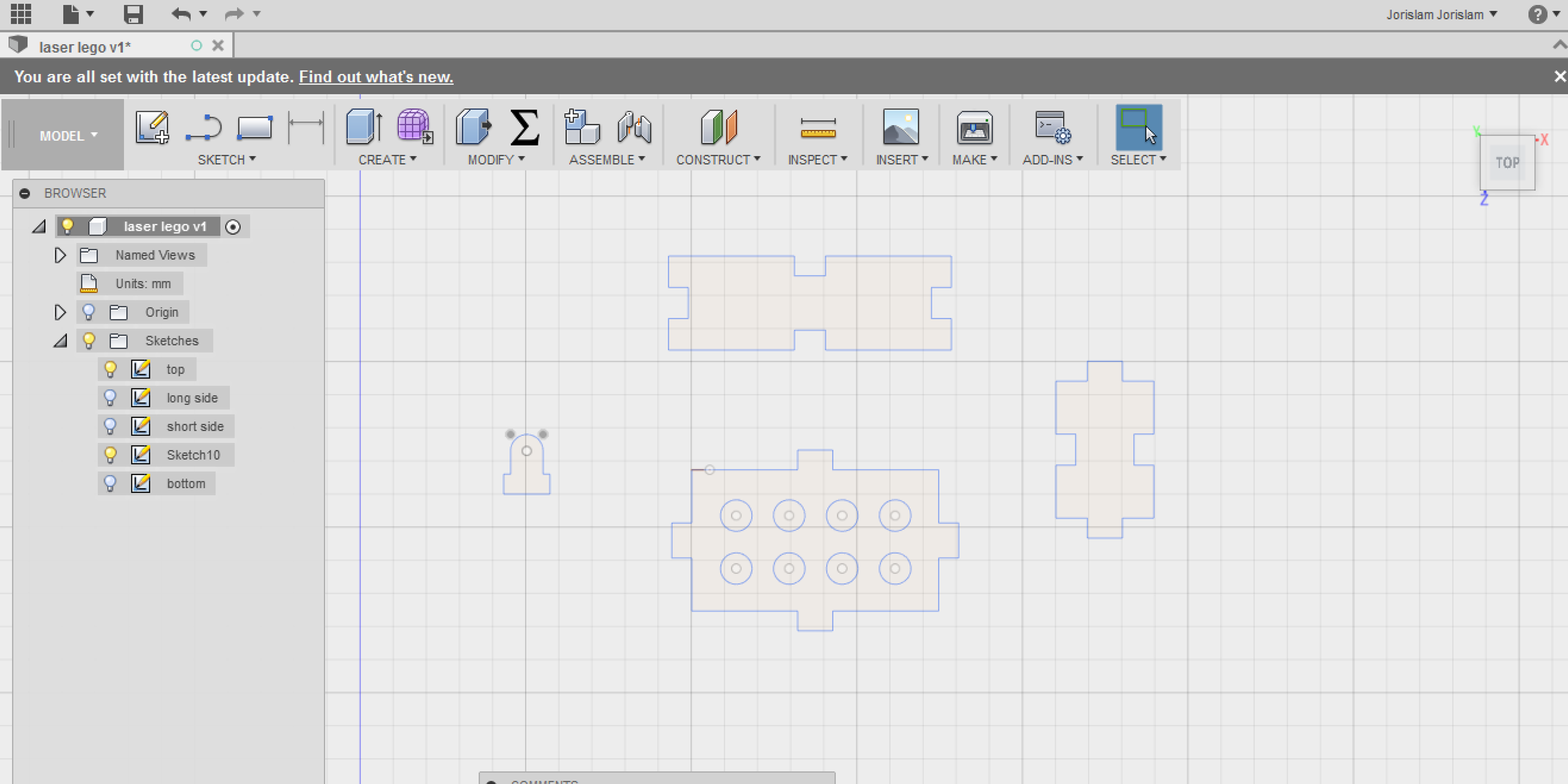
It only has four sketches, the basic three components for the brick itself you just need to cut twice, and the stud piece you simply cut eight times for a classic brick, sixteen for a double male version.
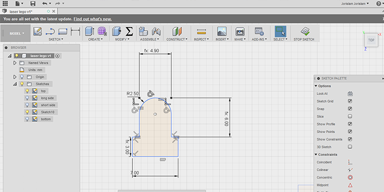
stud design
I gave the studs a big fillet at the top, making them easier to slide through the main brick, and it works nice with original LEGO pieces. The fit at the bottom is not corrected for the circle diameter and hardly corrected for kerf as you want an extremely tight fit between the stud and the brick it belongs to, but still be able to endure pressure from when a brick is placed on top as it has to snap fit to the next set of holes. This fit is particularly tricky because I wanted their to be no difference between a bottom or a top part of the brick for easy assembly. In a perfect world the bottom part would have a slightly wider set of holes, but since it would be very hard to tell them apart I decided to keep them the same and just try to find the perfect fit for both.
kerf consideration
First of all, when making finger joints like I did, remember that cutting loss occurs four times per part. Two times on each side of the joint for each component. That is why with finger joints, you must specify the male part of the joint to be the width of the joint PLUS kerf, and for the female part MINUS the kerf, as the kerf makes the male part smaller and the female part wider.
What was a really hard part about this design was getting a the kerf of a circle right to snap fit the LEGO brick. I made about ten different tests to get it right. Later I thought of the fact that I could have probably made a kerf test file with circles similar to the one with rectangles, but I did it the hard way. These are all the variations I evaluated:
The kerf for the finger slots I got right on the first try,
because I had an indication from our kerf research. However,
acrylic is very fragile when stress is applied, so upon assembling
them I did break quite a few pieces. Also the bed of the laser cutter
wasn’t completely level, making some pieces fit better than others.
oops
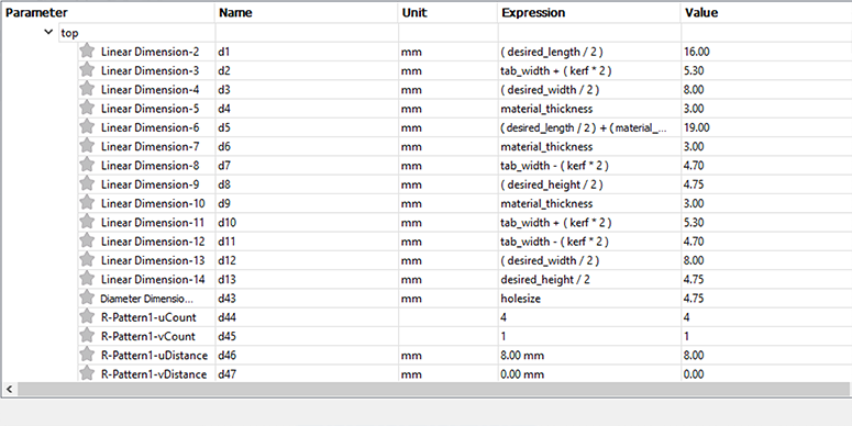
One mistake I made is that I made all the components in the same sketch,
and porting them to a new sketch proved weirdly hard as they lost their
constraints, so unfortunately in my formula I could no longer specify
which line belonged to which part. The solution? I gave all the
dimensions in the sketch unique dimensions that I could remember,
so I knew for example that if in the parametric editor I saw 6.3mm
that that was the tab width for example.
PROCESS FROM FUSION TO LASER CUTTER
How to get your design from Fusion 360 to the laser cutter.
This varies for each Fab Lab and laser cutter so I will try
to give a more generic step by step rather than talk about
local peculiarities our machine has.
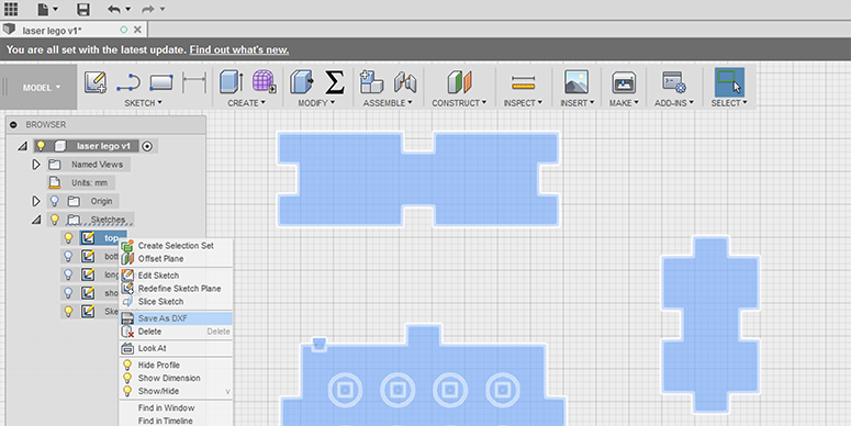
1 - DXF export
To get a DXF of your sketch in Fusion 360, go to the sketch in your browser, right click it and select ‘save as DXF’. Note, this does not work when the sketch is active, so if it is, click stop sketch first. You cannot select a single part of your sketch, so that is why it is important to have different components in different sketches. Because I did this wrong I could only export all my components as one.
2 - resolve issues
Two common problems occur when exporting DXF’s from Fusion.
One is files not being able to be opened by buggy laser cutter
software or that the scaling is read wrong by the laser software.
To solve this, import the DXF in Rhino and export it again as DXF.
It’s the most simple set of actions you can take, but it both files not being able to opened or wrong scaling.
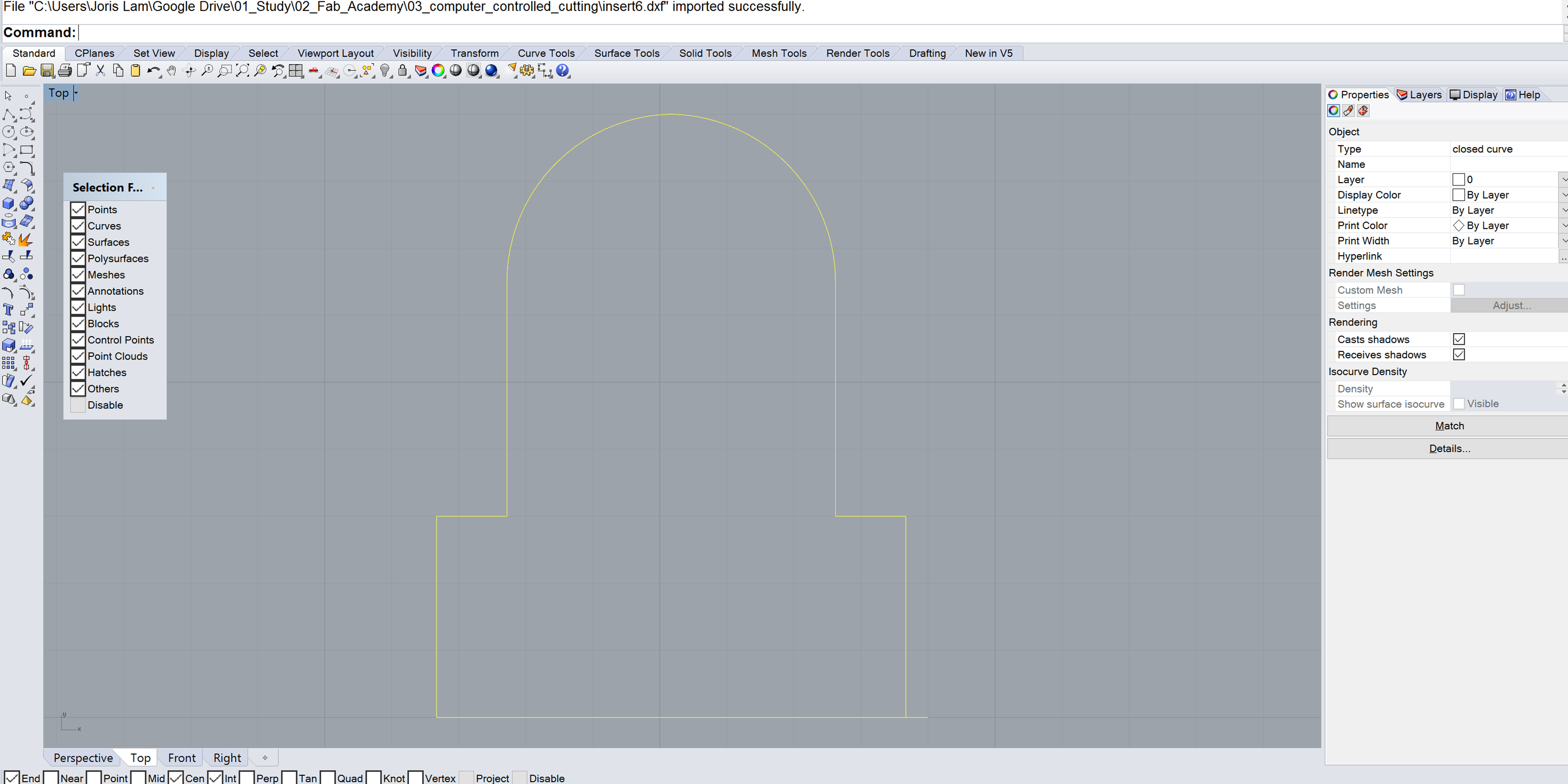
The second issue with DXF files from Fusion 360 is that sometimes
it will make construction lines that should be invisible into actual cut lines.
Whatever you do, DO NOT delete these construction lines in Fusion,
as you will break constraints or parameters attached to them.
Instead, if you encounter this problem, either delete the unwanted lines in
the laser software, or open the file in Rhino or Illustrator, delete them
there and save as DXF again.
Notice how there is a small line that appeared in Rhino when performing this
action on the stud piece, in Rhino you can simply remove this error.
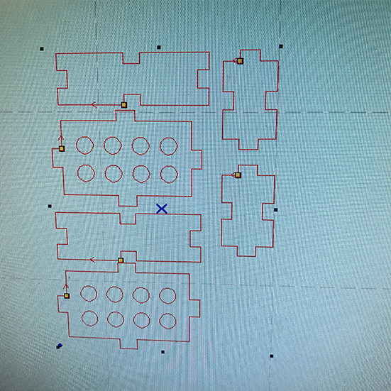
3 - arranging components
This step various from machine to machine, but in general, you
will need to take your DXF files, import them into a plane that
resembles your machine and arrange them optimizing the material you have.
I never arrange the components in the design software, but I wait to do
this in the laser software because I try to fit everything into unused
pieces of material and this varies every time you make a cut, so this
should be done when you’re preparing your files for the laser in this final step.
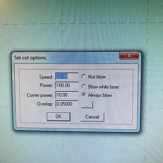
4 - setting power and speed
In general, the slower your laser goes, the less power it needs,
but the more it might burn in some cases(cardboard!) but this step is
really just trial and error. See if there are any references for your
type of material in your local lab and if not, experiment away.
You generally want to keep the speed as high as you can because it
simply takes less time to make something. For the 3 millimeter acrylic
I was going to cut on a 100 Watt BRM laser I used speed 20 en power 100.
5 - focal length
The lens of the laser should have the correct distance from your material,
this is different from machine to machine, but we have a handy little tool in
the lab that tells you if the distance is right. Adjust the laser head accordingly.
On BRM machines I like to do this manually for the last millimeters so I don’t risk
cracking the lens. On Trotec machines you use a totally different tool,
check with your local laser guru on how to do this in your lab.
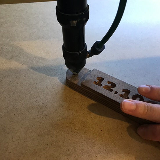
If your focal length is wrong, you might see something like
this: This happened when the vibrations made the laser head come down.
6 - go!
Ventilation running? Laser powered on? Lid shut? Let’s cut this baby!
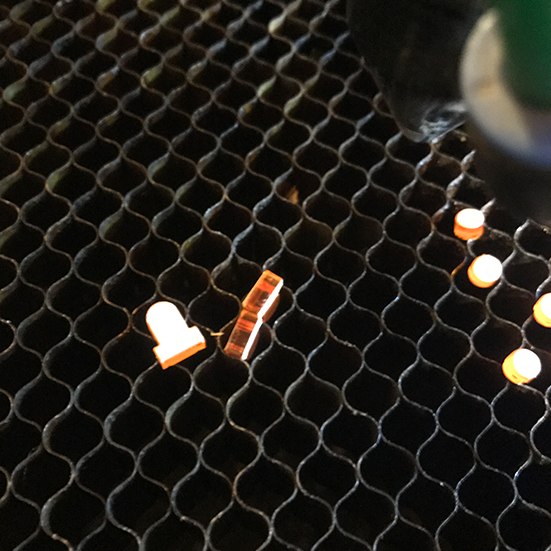
7 - results
First of all, I couldn’t have gone much smaller with the studs,
as they almost fell through the honeycomb bed, a solution to this
could be to design it with a very thin attachment to the left
over material and break it off once you take the sheet of material
out of the laser. But luckily I didn’t have to do that.
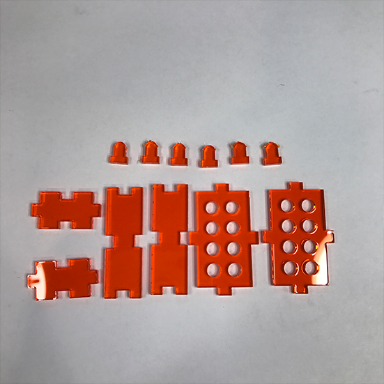
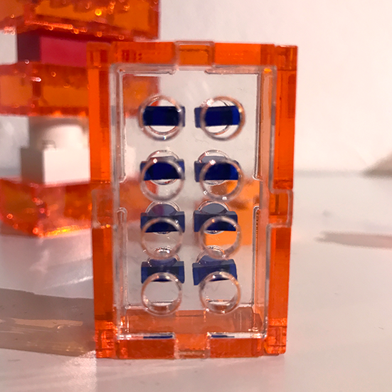
These are all the pieces needed for one ‘LEGO-laserbrick’:
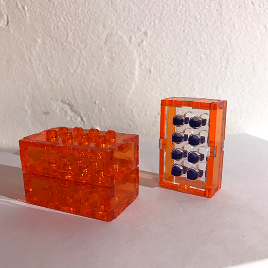
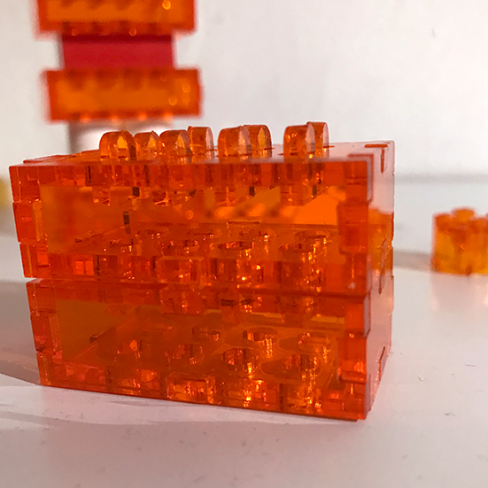
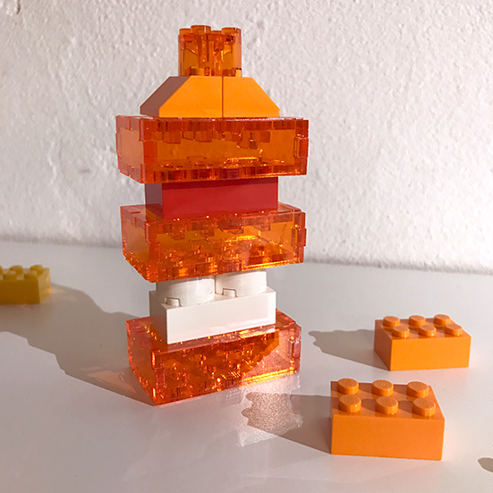
HERO SHOTS
Here you see the final results and how the bricks fit together both on
their own and combined with LEGO:
CONCLUSION
I think there is a lot of potential here for my final project as it is completely possible to laser cut objects that are compatible with LEGO. This opens up a lot of possibilities, but kerf is more important than ever with this project. What really needs improvement are the possibilities for different brick sizes. Right now the laser cut brick is bigger than it’s injection moulded counterpart which has some limitations. I think this can be improved by using two millimeter acrylic instead of 3 millimeter, by making the design more compact and by possible adding indentations on the outer edges. Right now it’s a proof of concept that laser cutting and LEGO can indeed be combined, now it just needs a lot more engineering effort to perfect it.
If you want to play around with my files, please download them here, and don't forget to shoot me an email if you discover something cool!
Some people have issues downloading the file, if this is the case, please use this link:
Click! .
parametric laser cut LEGO brick Fusion 360