computer aided design
Because I want to make a modular prototyping system based on the LEGO brick for my final project I decided to use this week to see if I could make a parametric script that allows anyone to easily make LEGO compatible designs.
To see if I can use Fusion 360 for 2D work and designs to cut I will also evaluate this proces after all the 3D work on this page.
At the very bottom of this page you will find my conclusion about the various software solutions as well as the files to download. When you download these files and make great improvements I would love to hear about it! Send me an email via jorislam@gmail.com if you make great discoveries!
The two options I identified at first for 3D design are Rhino with Grasshopper, but since I’m also learning Fusion 360 I started with that solution.
My goal is to create parametric rules or a script that allows me to create LEGO compatible components easily and indefinitely, but the components must follow the LEGO design restrictions to make sure it fits the most commonly found LEGO bricks.
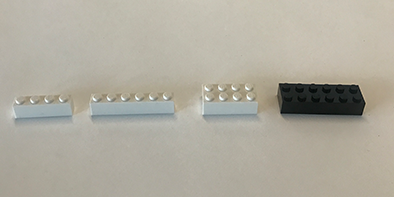
I analyzed the anatomy of various bricks and the most important conclusions are:
-Except for the single brick, all other bricks have even numbered amounts of studs.
-All bricks have the same basic ratio, stud sizes etc.
-The most useful and universal bricks are four in a single row, six in a single row, four in a double row or six in a double row.
This is a great resource to learn more about the dimensions of LEGO bricks.
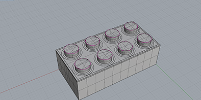
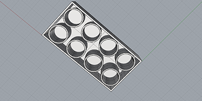
To learn about parametric design I first focussed on just creating bricks in the right dimensions with the right amount of studs with the correct spacing. The bottom or female part of the brick varies more so I have yet to design a universal parametric alternative to the bottom part of the brick.
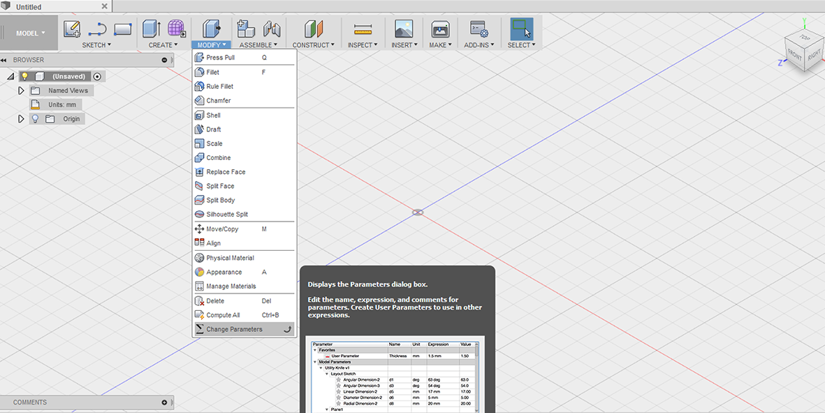
In Fusion 360 there is a ‘change parametrics’ option under the ‘modify’ drop down menu.
My first mistake was that I thought I could just add parameters to this blanc table and that object would appear, wrong! In order to make or adjust objects with parametrics you have to create an object in the GUI first, and only then can you modify its properties parametrically. Because LEGO bricks are usually a multiple of two, I started by creating a basic shape that has the dimensions of a standard two-stud brick which is: 16X7.9X9.6mm.
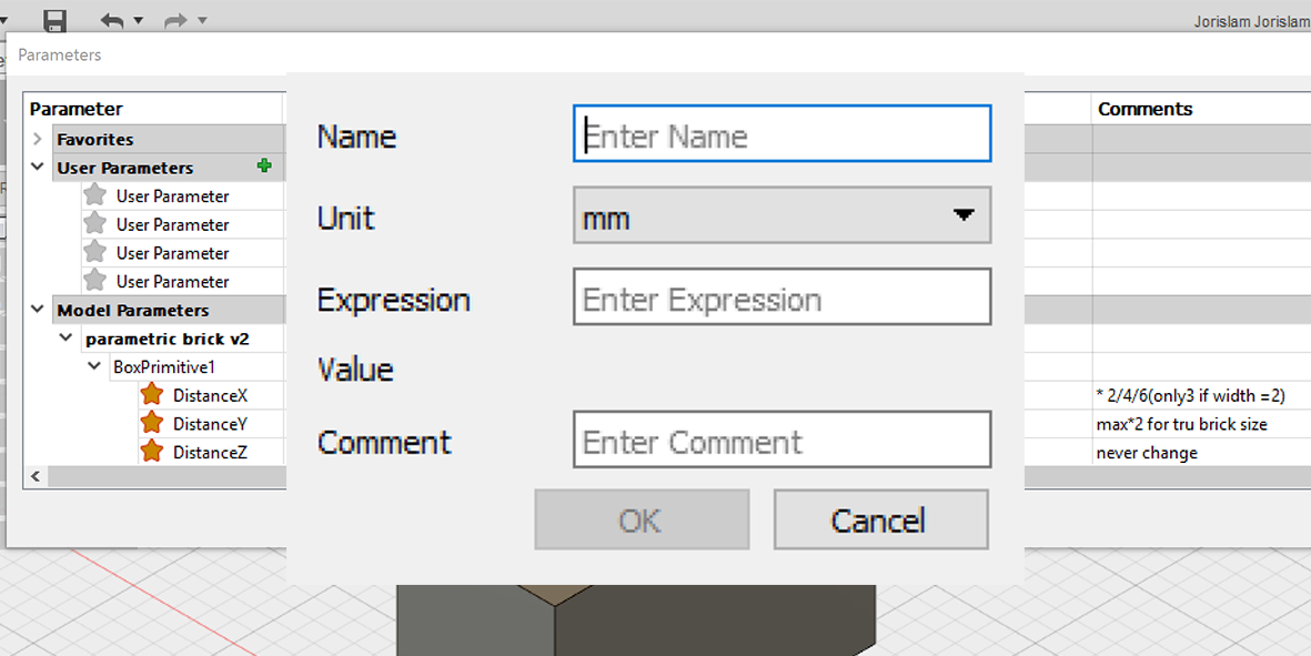
When you open the ‘change parameters’ menu you see:
-favorites
-User Parameters
-Model Parameters
The user parameters are empty because it’s up to you, the user to give those content.
But, this is the part that was an ‘aha!’ moment for me, the model parameters have now been filled out because you have made a simple block in the GUI.
You will see a box primitive with the following values filled out:
-DistanceX
-DistanceY
-DistanceZ
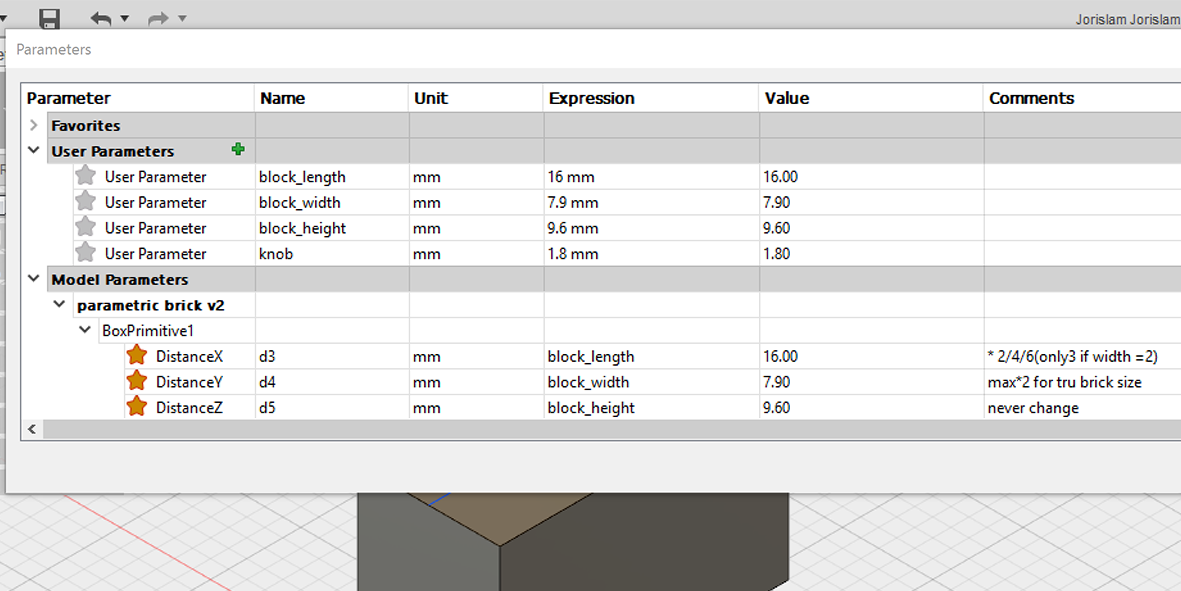
These are the basic values you want to be able to change as you want bigger bricks, so in order to make everything a bit more clear, in the User Parameters I created names for the values of this block.
First you give your parameter a logical name, like block_lenght(note, you can’t use spaces or funky characters) then you give it the correct unit, mm in this case and then the expression, and if it helps you a note.
In this case, I filled out all the basic parameters for this brick, so that I can easily type modify commands and know what part of the brick it’s about. To get started with the actual model, I replaced the numerical expressions with the user parameters I had just set, so for DistanceX, instead of 16 I wrote ‘block_length’ in the expression field. This I repeated for the other values of the brick. In the notes I put some restrictions you need to follow to create bricks that adhere to the original design options, but you can obviously create franken-bricks and go crazy with all the values. The only thing you should never change is the stud value and the height.(but again, maybe you want your own system, so never say never)
Now if you want a brick that is twice as long, all you have to do is change the model parameters and in expression declare ‘block_length*2’. Click OK and see the larger brick with the right ratio.
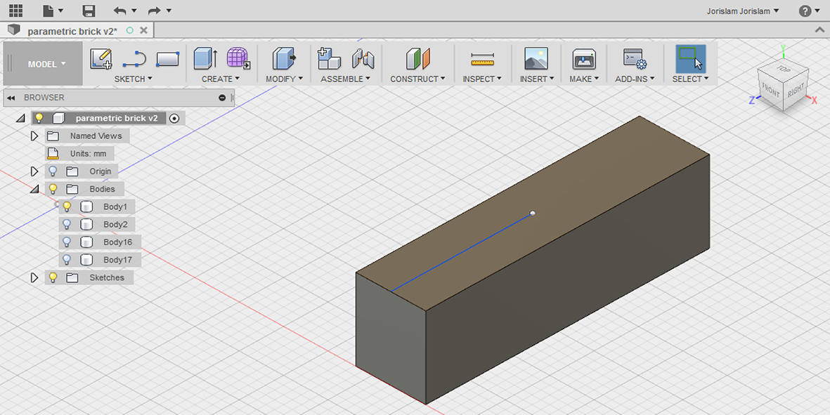
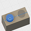
Ok, now we’ve got the basics down for a brick that can get bigger with the correct ratio, but we’re missing the studs, and getting this right took me quite some time to figure out. With the studs, they should not only hold the correct size, but also the correct space between them as the brick grows. At first I thought I could do this by simply declaring this out of the blue in the parametric table, but I was wrong. In order to get working with parametrics in Fusion, you first need to build something in the GUI that you can later adjust with parametrics, so at first I thought I could just make two new bodies in the right size in the right place and multiply that parametrically, wrong again, because the spacing between two bodies doesn’t hold any spacing information. The answer? A pattern! I’m not going to bore you with how to get a body in the right position on another body, that’s just a matter of construction lines and the ‘align’ button, but once you have you first stud in place, it’s time to pattern it!
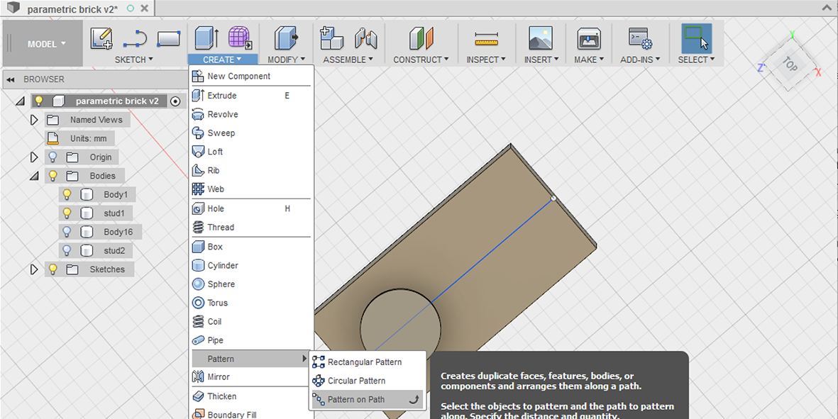
To help guide your studs in the right spacing, first, draw a line straight across the top face of the brick.
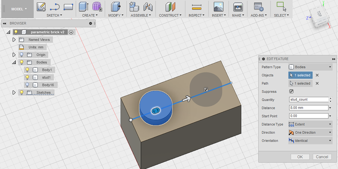
 Then, from the ‘create’ menu, select ‘pattern’ and ‘pattern on path’.
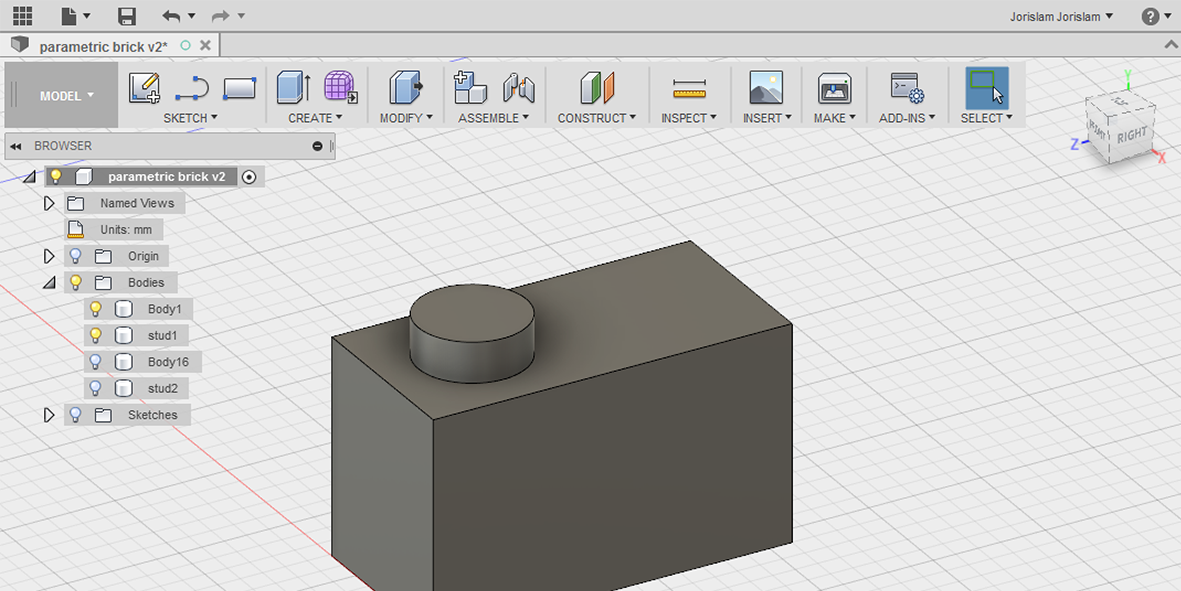
Set the right direction and set the distance at 8mm.
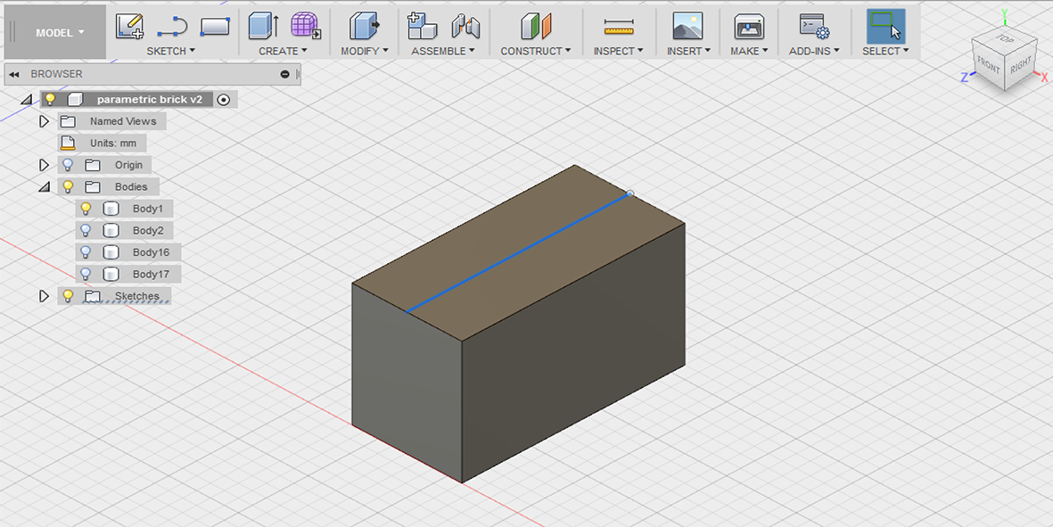
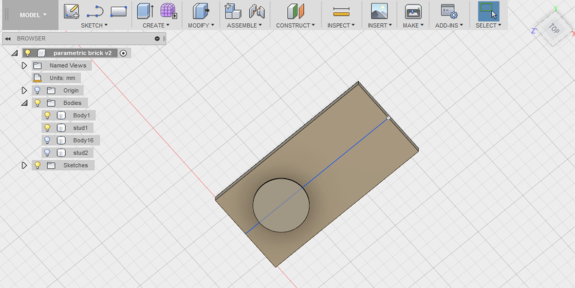
 And now you have two studs, but more importantly, there is a link between the space of the studs!
 When you go back to the ‘change parametrics’ menu, you will now see a new tab, called ‘PathPattern1’, which includes ‘countU’ and ‘PathPatternDelta’. The PathPattern is how many studs there are and the PathPatternDelta is the spacing between them.
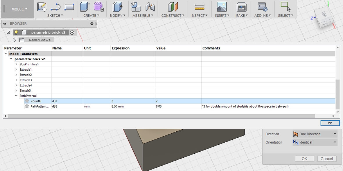
Now, when you want to add more studs to your brick, simply replace the 2 with the number of studs you want, but beware! You also need to adjust the PathPatternDelta, and you might think you could just multiply that by the same amount as the studs, but that’s not the case.
My first thought was, if I go from a studcount of 2, to 4, then I’ll just add *2 to the patterndelta, but then the spacing is off. This is because the patterndelta doesn’t reflect the amount of studs, but it reflects the spaces between them. When you have four studs, you have three spaces of 8mm in between them, meaning you should multiply the patterndelta by 3, not by 2.
To clarify:
studcount 2 = patterndelta 8mm
studcount 4 = patterndelta 8*3
studcount 8 = patterndelta 8*7
etc.
To make this easier, I just added two more user parameters, stud_count, which I set to 1(unit, not mm!) and stud_space which I set to 8mm.
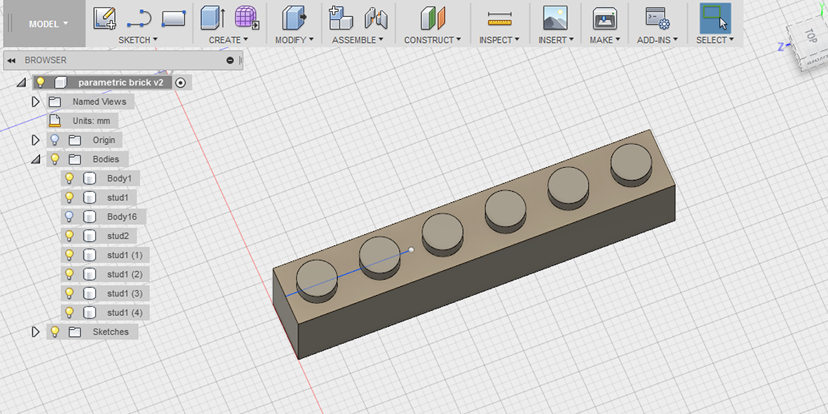
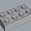
So now we have all our basic parametrics in place, let’s give this brick a spin! Let’s say instead of the two stud brick I want a six stud brick, then I fill in this:
block_length * 3
block_width (no changes here as I want a single row)
block_height (no changes here either, remember ;)
stud_count*6
stud_space*5
And now you have a parametric brick that adheres to all the physics of the original LEGO!
Next challenge will be making this for the bottom part, more on that to come. Another thing I will add soon is how to make double row bricks.
NEXT UP, OTHER SOFTWARE
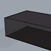
Part of this week’s assignment is to try as much different pieces of software as humanly possible, so to I went ahead and gave Rhino a try with the help from our local instructor Nina. What we did was try to design an alternative to the female side of a LEGO brick that will be easier to scale parametrically.
One of the main aspects that a lot of people like about Rhino is that you can ‘talk’ to the software by just typing commands. It has a certain rhythm to it of typing, hitting enter, entering values and hitting enter again. Once you get into it it speeds things up, but you have to take the time to get used to it.
In Fusion you can also hit ‘s’ at any time and then start typing or searching for commands, tools, etc. pretty handy if you’re coming from Rhino!
Our local Rhino/Grasshopper ninja Nina Papakonstantinou helped me investigate if the parametric brick system could also be applied to a case that automatically generates studs on the edge and bottom. She made a great script in Grasshopper that I will post in a public repository soon so everyone can build upon it. My Grasshopper skills are terrible so I can’t really tell you much about the process but I’m going to investigate this software in the future.
This file was made by Nina as an exploration to see if what I had in mind could infact be made in Grasshopper, or if I should try other software. The conclusion is it can definitely be done, but since my knowledge is so limited I will either try to recreate this in Fusion 360 later, or study Grasshopper tutorials so that I can recreate this myself. If anyone wants to use this file, it's available to download at the bottom of the page.


We also got a workshop for FreeCAD, which is very powerful when designing parametrically.
To get an idea of the software we followed a tutorial to make a knob for an audio mixer.
The big difference between how this design process works and how I usually design in Fusion 360 is that you start with a shape regardless of its dimension and then later give it those constraints. In Fusion you have a timeline at the bottom of your screen and in FreeCAD this timeline is on the left and plays a more prominent role in designing.
One really cool function in FreeCAD is the ability to make and export technical drawings from your design.


2D PARAMETRIC DESIGN IN FUSION 360
To learn 2D (parametric) design I once again turned to Fusion 360 to see if this is also possible with this software. The short answer: yes it is, the long answer, well see below on how I got making a simple parametric DXF file ready for the laser cutter.
The objective for my parametric drawing was: make a finger slot type line that can parametrically correct the laser kerf or material thickness.
To start I drew a simple using the line command in the sketch menu. If repeated this sketch would form a finger slot style line, I thought.
Based on my previous experience with the LEGO brick I immediately went to the ‘change parameters’ button, but I couldn’t find any model parameters to adjust! Aaaah! Drove me crazy! When I made an object like a cube it would show up in the parametrics table, and sometimes when I made a sketch it showed up, but not always.
It took my about four hours to figure it out, but this is what happened:
When you just draw a sketch, without typing in dimensions and hitting enter, the sketch remains just a sketch and it doesn’t show up in the parametrics table. But when you’re making the sketch and you type in numbers and hit enter every time it does show up!
But what if you just want to make a sketch and worry about the dimensions later but still want to edit it parametrically? There’s a solution for that too, when still in sketch mode, go to the sketch menu and choose ‘sketch dimension’. This allows you to give a dimension to a part of a sketch after it’s been drawn and doing this also enables parametric editing in the table. Mystery solved.
Now I knew how to make sketches appear in the ‘change parameters’ menu to begin with, BUT that didn’t mean I now had my parametrically adjustable finger slot cutline.
To get a parametric cutline, I did the following steps:
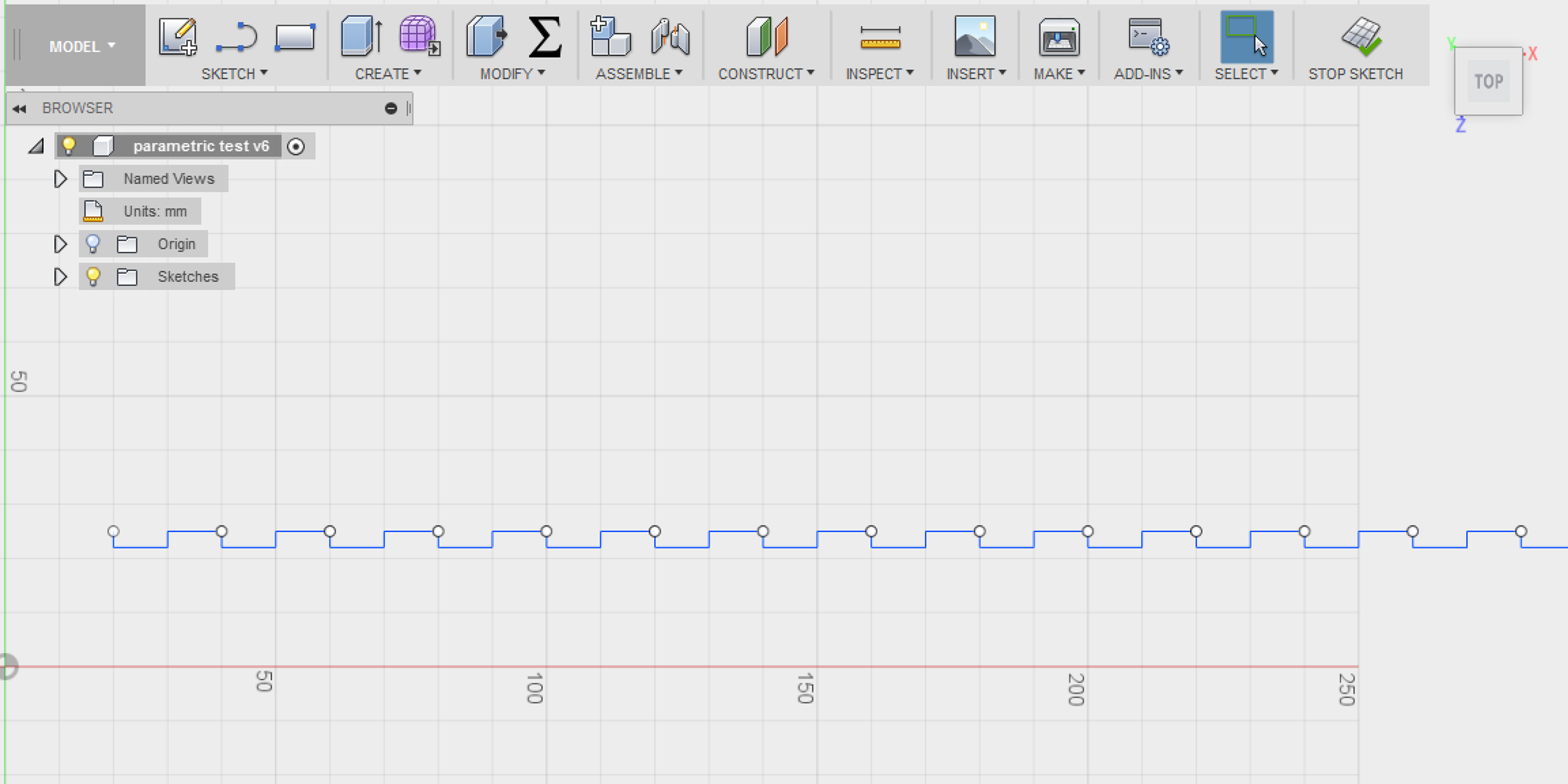
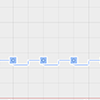
1 - make a sketch out of lines that is repeatable.
No dimensioning, no parametrics, just a sketch with global dimensions, it doesn’t really matter what the dimensions are since you’re editing those later. VERY IMPORTANT NOTE: do NOT start your sketch at the center point of the plane, for some reason this locks it and will not repeat the pattern you need to make in step 2. Instead, just pick any point in space that isn’t snapping to any line or midpoint.
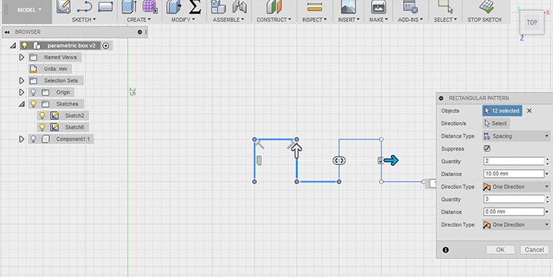
2 - make a repeating pattern
Do this by using the ‘rectangular pattern’ button in the sketch menu(not in the create menu since that one only applies to bodies, not sketches! Just give it a repeat quantity of 2 and some random spacing number, again, you’ll set this straight later. Make sure to set the ‘distance type’ to spacing instead of extent.
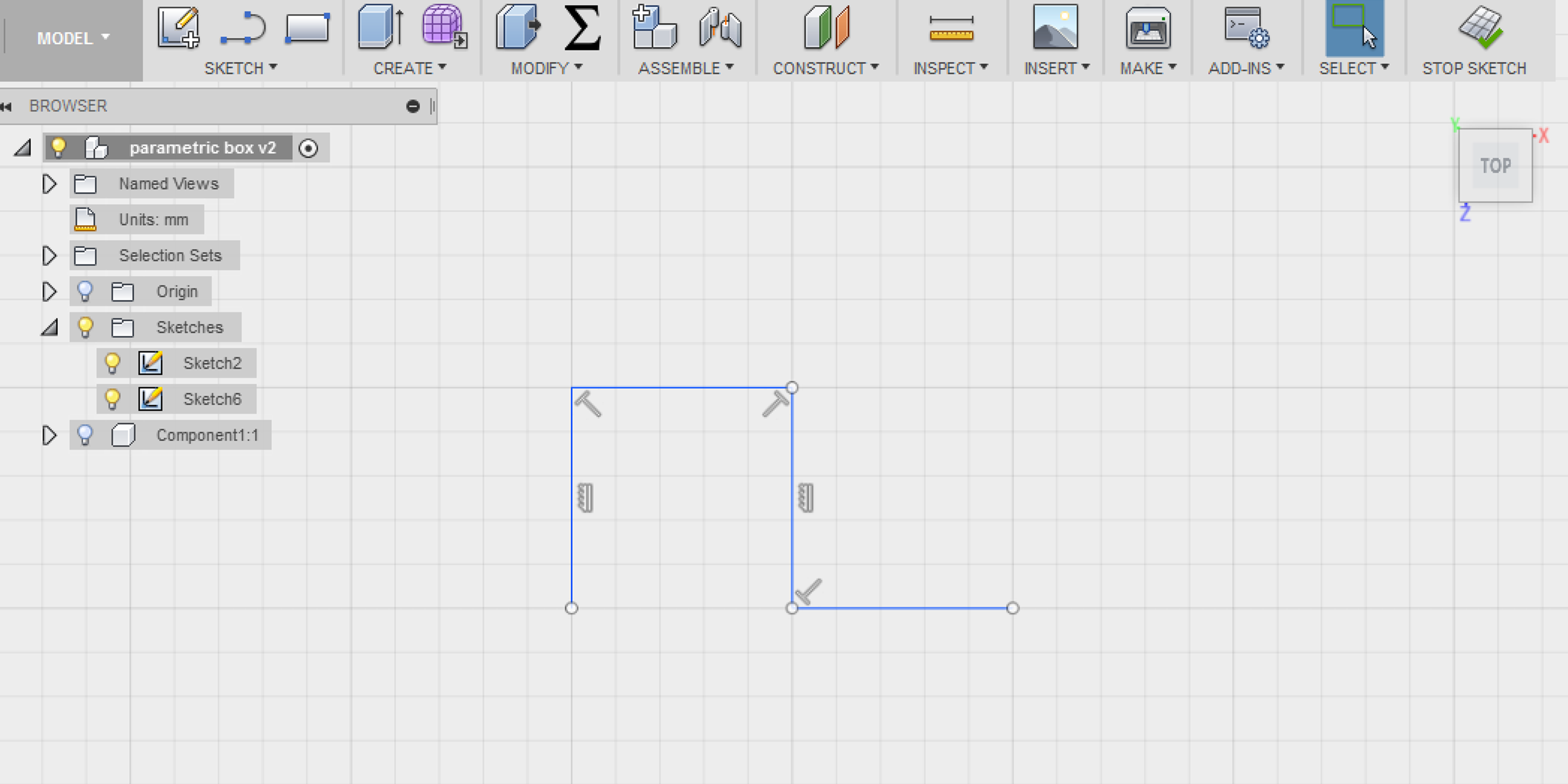
3 - sketch constraints
give the original sketch(not the patterned second one) some sketch constraints using the ‘sketch pallet’. Use the ‘equal’ command to link both horizontal lines to each other making sure they always stay the same size, and do the same for the vertical lines. You do this by clicking the ‘equal’ symbol in the sketch pallet, then clicking the first line once, then clicking the second line you want to have the same dimensions once, and done. Do not forget to unclick the ‘equal’ button before reactivating it again to make the other set of lines equal, otherwise they’re all linked and that’s exactly what you don’t want.

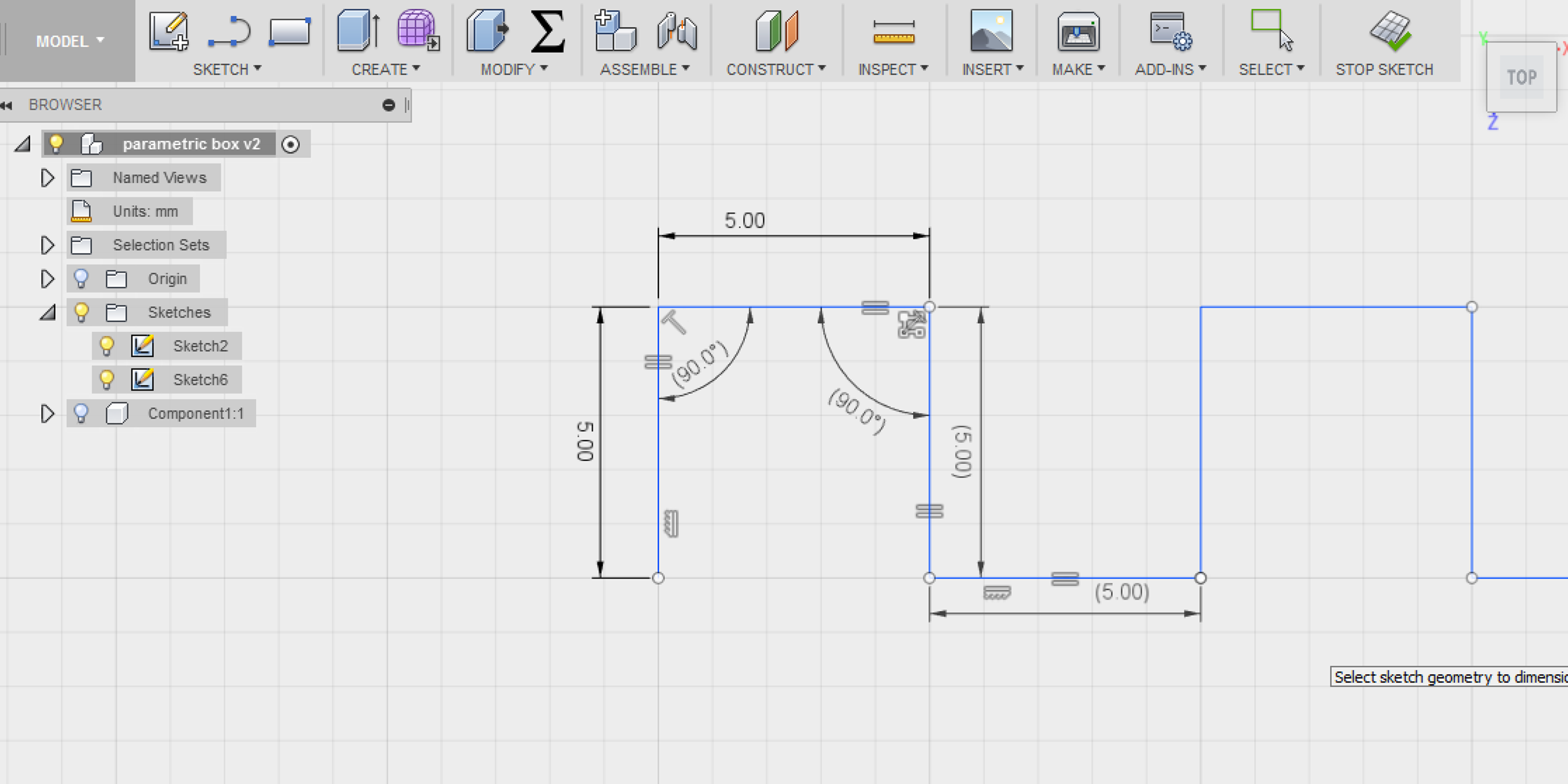
4 - dimension sketch
Using the ’sketch dimension’ tool, give each line in the original sketch(not the patterned second one) some dimensions, it still doesn’t matter much what you give them, as long as it’s not so crazy big that you can’t see what you’re doing anymore.
Click on each line in the original sketch to give it a dimension, like 5mm for example, and then click on two lines one after the other to set the radius of the angle between them, this should always be 90 degrees.
You might run into the error message saying ‘sketch geometry overconstrained’. If it just says it but still let’s you perform your operation you’re good to go, if not, you have made a mistake somewhere. This error basically tells you there are too many or conflicting constraints on the sketch. For example, after you’ve declared that two lines should always be ‘equal’ you can’t give one of them a different sketch dimension than the other, as that conflicts what you’ve just done.
5 - fill out parameters
Now it’s time to make this sketch do what you want without losing it’s spacing or other important constraints. Even though looking back on this table it now all makes sense, I was really struggling with finding the right values and computations for this.
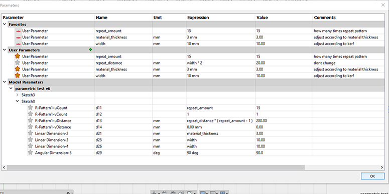
When copying this table, start by writing the user parameters, then adjust the model parameters accordingly. I starred the user parameters that you can change according to things like material thickness and width and how often you want this repeated.
It seems so simple yet it took me forever to figure out that in order to get the pattern repeated with the right distance you have to set the user created ‘repeat_distance’ to width*2, and then in the model parameters set the ‘uDistance’ to the earlier specified ‘repeat_distance*(repeat_amount-1). Sound confusing? Let me break it down: the distance between two sketches or bodies when you repeat it using a pattern needs to know how great this distance is, but as you might remember from the LEGO brick, this distance number isn’t the distance from the beginning to the end of the sketch, but this is just the spaces in between. This means that if you repeat something four times, you only need three ‘distances’. That is why in this command it specifies the repeat distance as a number equal to how often you repeat it, minus one: repeat_amount-1. Because in this case you might want to edit the width of the joint, it’s important to keep the user specified width in the formula, that is why the repeat_distance is the width*2.
If all is well, now you should be able to edit the width or material thickness and amount of repeats and all should scale beautifully!

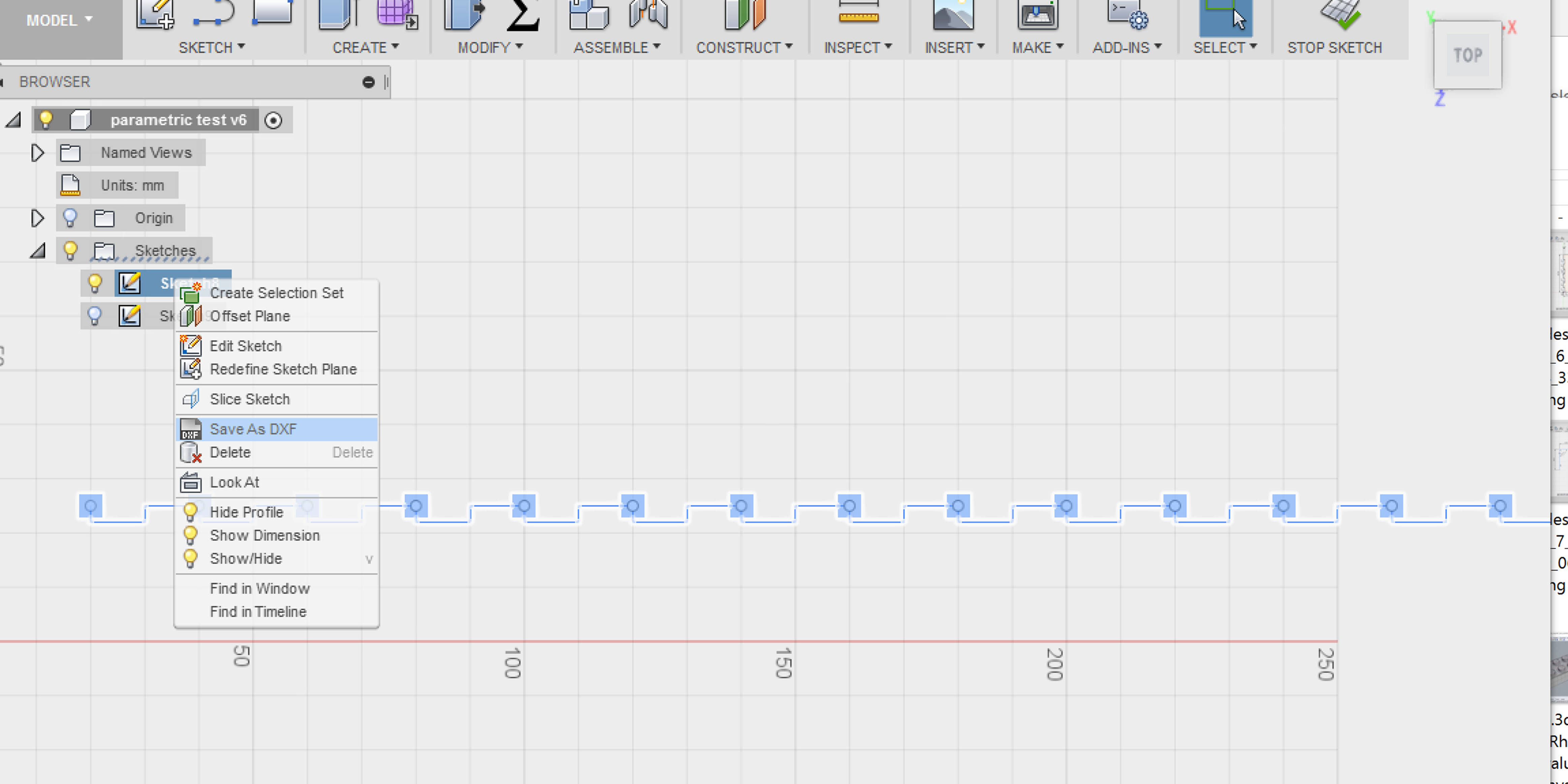
Finally, to export this to a DXF format the lasercutter can read, go to the sketch in navigation menu on the left, right click the sketch and choose ‘save as DXF’.
Now this is just one cutline, to make this really useful you have to apply this to a box for instance, this is something I will work on in the future to get right.
CONCLUSION
I already had in my mind that I wanted to explore Fusion 360 more than other software because I really like the integration of modeling, animation, rendering and their cloud based file storage solution.
But in order to be useful for Fab Academy I reasoned that in order to be a useful piece of software it should allow extensive parametrical design and preferable also handle laser cut drawings well, as is the case with Rhino.
It took me quite some time to get into Fusion's parametrics logic, because it is basically spread out over two different elements of the interface, on one hand you have the timeline in the bottom that allows you to go back in time and make changes that affect all future actions, very much like it works in freeCAD, and then there is the 'change parameters' table function that I described quite a lot here.
I think both Rhino and Fusion are great tools for both 3D and 2D work, freeCAD is great for parametrics but has a steeper learning curve also due to the UI design as is often the case with opensource software. Rhino has the big advantage of having the Grasshopper plugin, but Fusion has the advantage of having a very integrated cloud based workflow and free cloud rendering, which is great if your machine isn't very powerful.
I can't decide for others ofcourse, but for myself I'm going to keep focussing on Fusion 360 as I like the interface, functionalities and cloud based environment. Having the files in the cloud allows me to collaborate with team members and keep good track of changes which is a big plus for me.
If you want to play around with my files, please download them here, and don't forget to shoot me an email if you discover something cool!
parametric LEGO brick Fusion 360
This is the link for Fusion 360 users to the file
LEGO brick Rhino
LEGO case Grasshopper
parametric cutline
This is the link for Fusion 360 users to the file(it doesnt show a preview because it is just a sketch and not an object)