WEEK 11
INPUT DEVICES
Assignment: Measure something: add a sensor to a microcontroller board that you have designed and read it.
Material: - sensor as input device: SR04 Ultrasonic Sensor
- electronic components for my PCB Softwares: - ArduinoIDE, for the programming
DETAILS
Milling a Satshakita 100% Arduino IDE and libraries compatible
As I'm only able to program via Arduino IDE, the PCB I will use is a Satshakit. Here is the Satshakit documentation, and here is the Satshakit GitHub page.
|
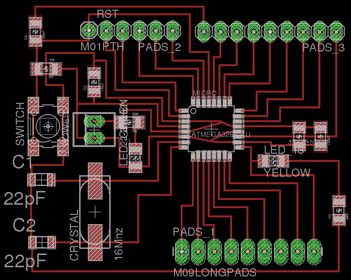
Here is the board view
|
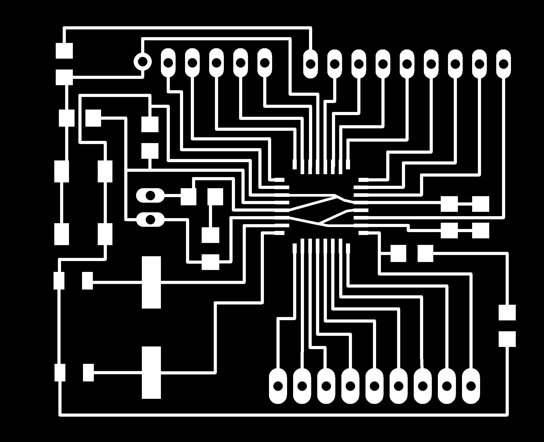
And here is the PNG file used
|
|
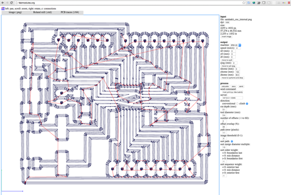
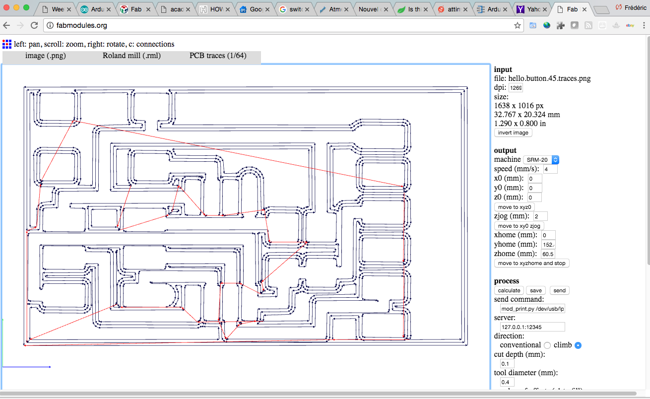
Using the FabModule to generate the Gcode
|
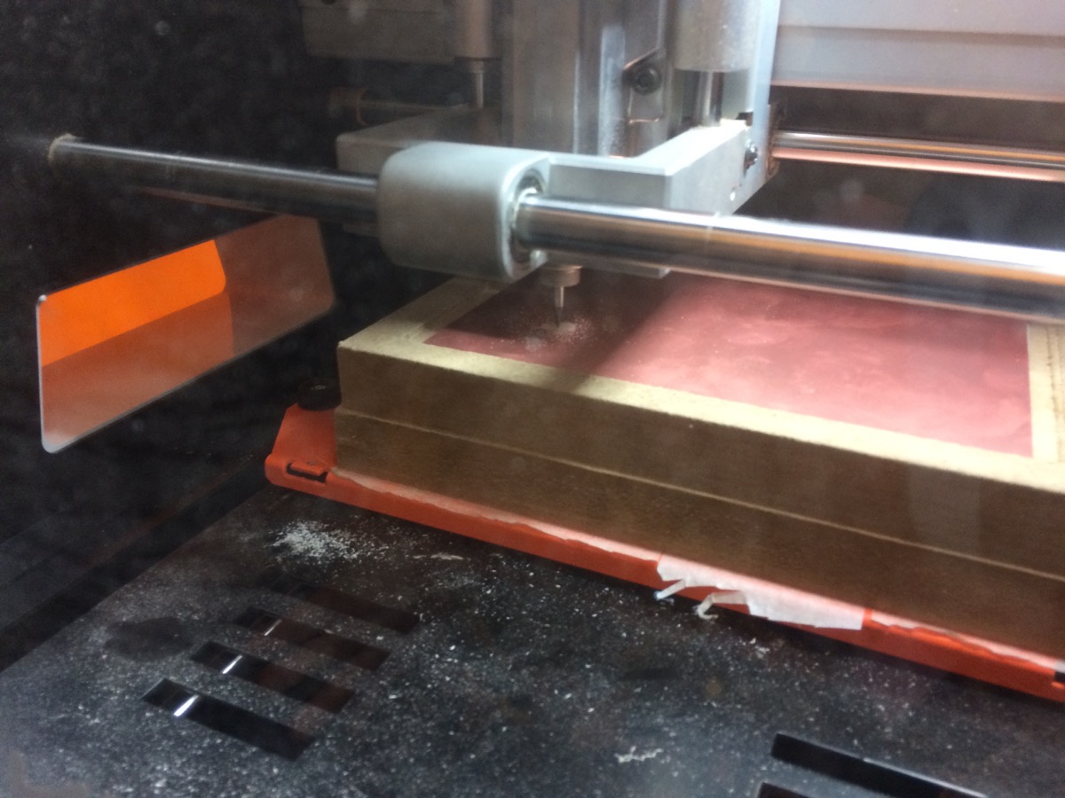
And a Roland monoFab SRM-20, to mill the PCB
|
|
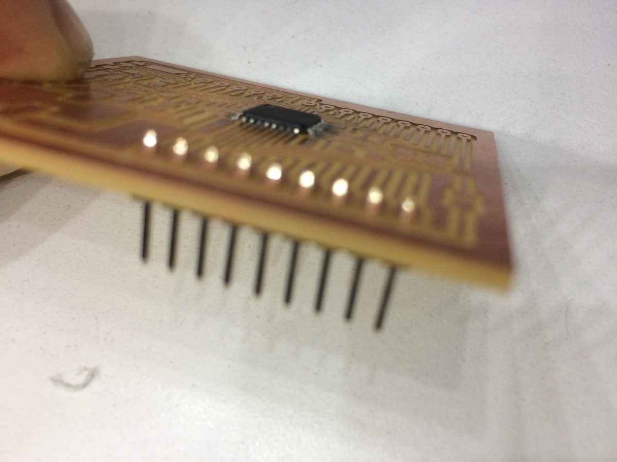
Now it is time to solder the components
|
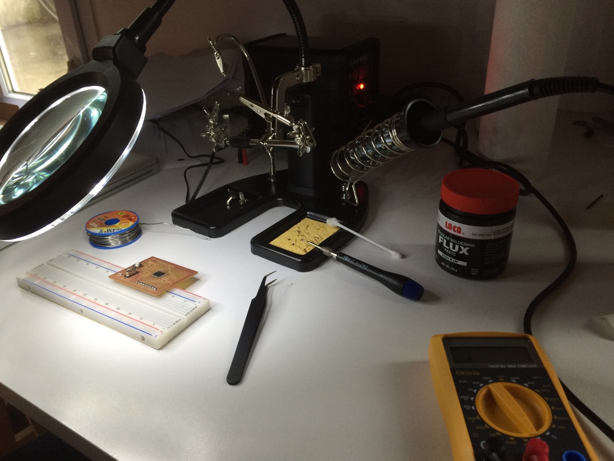
Here is my Soldering Lab at home
|
|
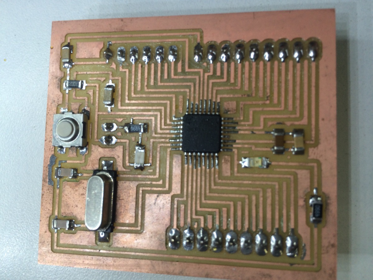
And the PCB finished
|
Burn Bootloader to my Satshakit
|
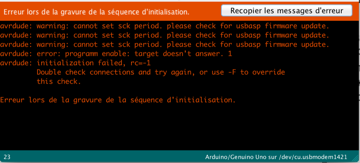
First a tried to burn the boatloader to my Satshakitusing USBasp key (a key I bought)
|
But I got an error, no chance to make it works
|
|
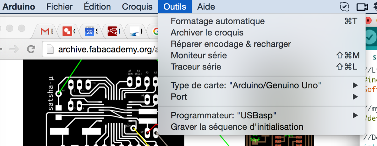
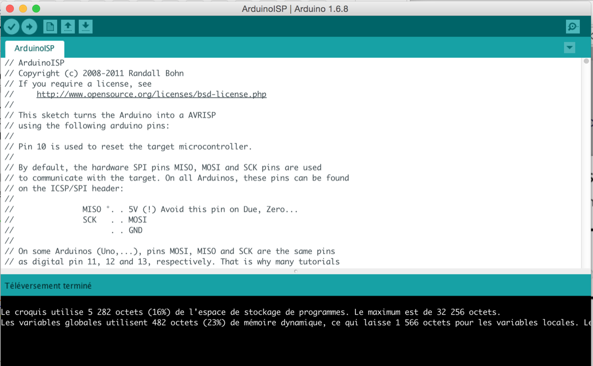
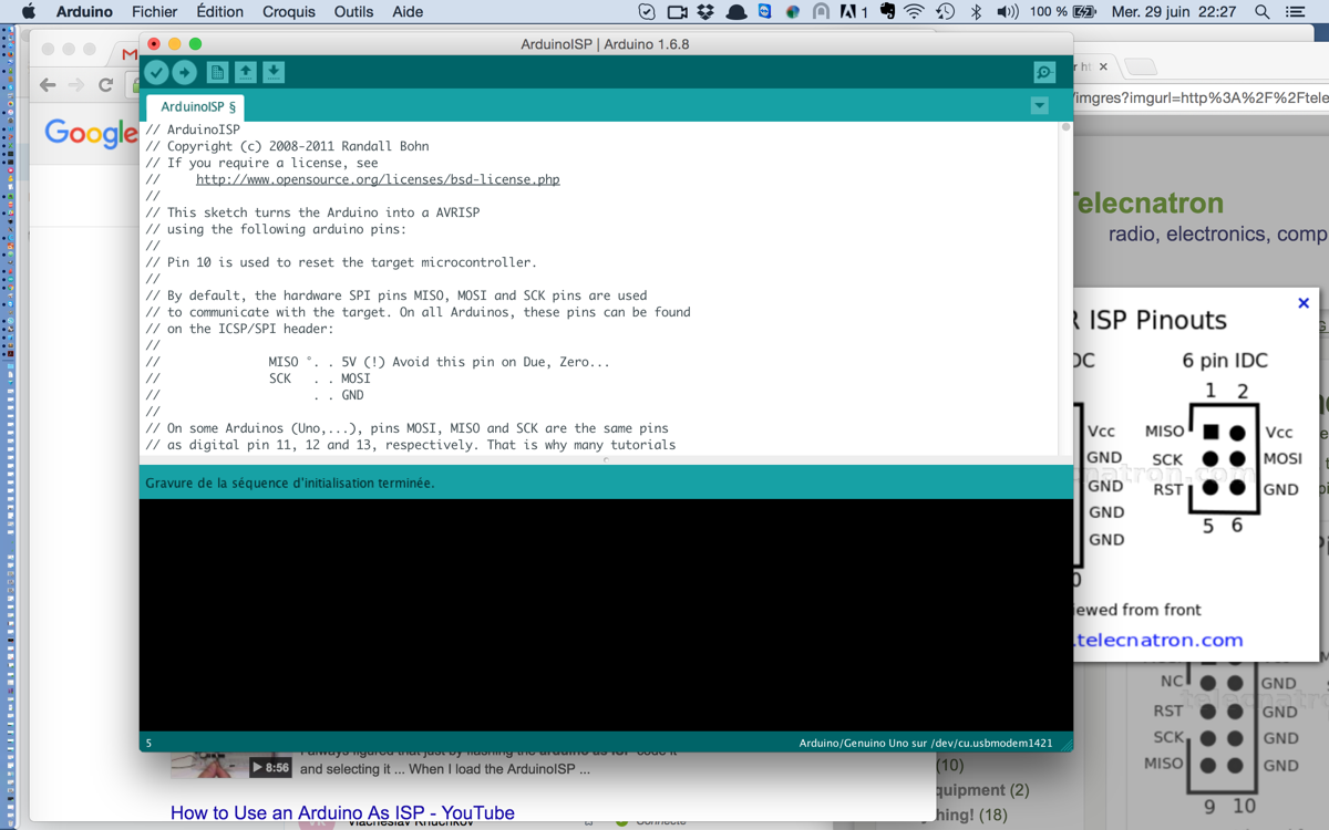
So I decided to use an Arduino Uno as ISPloading ArduinoISP to Arduino Uno
|
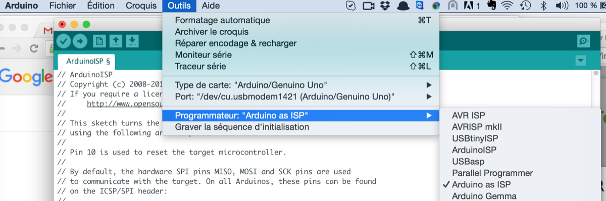
Configuring the Programmer correctly to "Arduino as ISP"
|
|
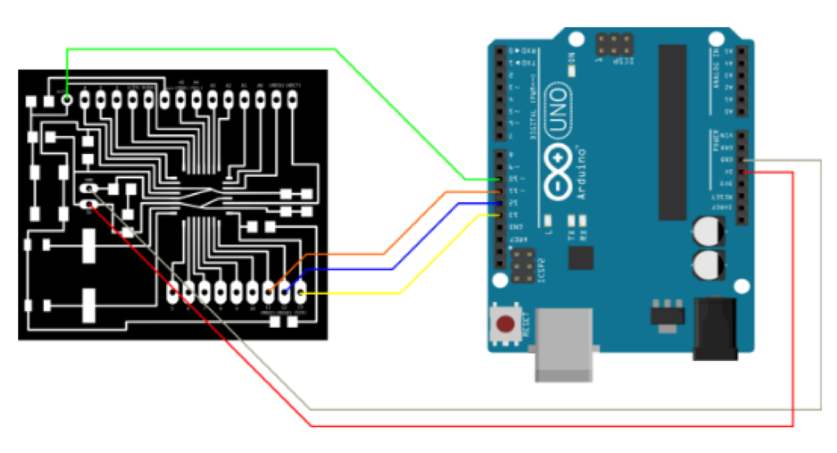
Here is the pinout Schema to use Arduino Uno as a ISP Programmer
|
This time Burn Bootloader was a success
|
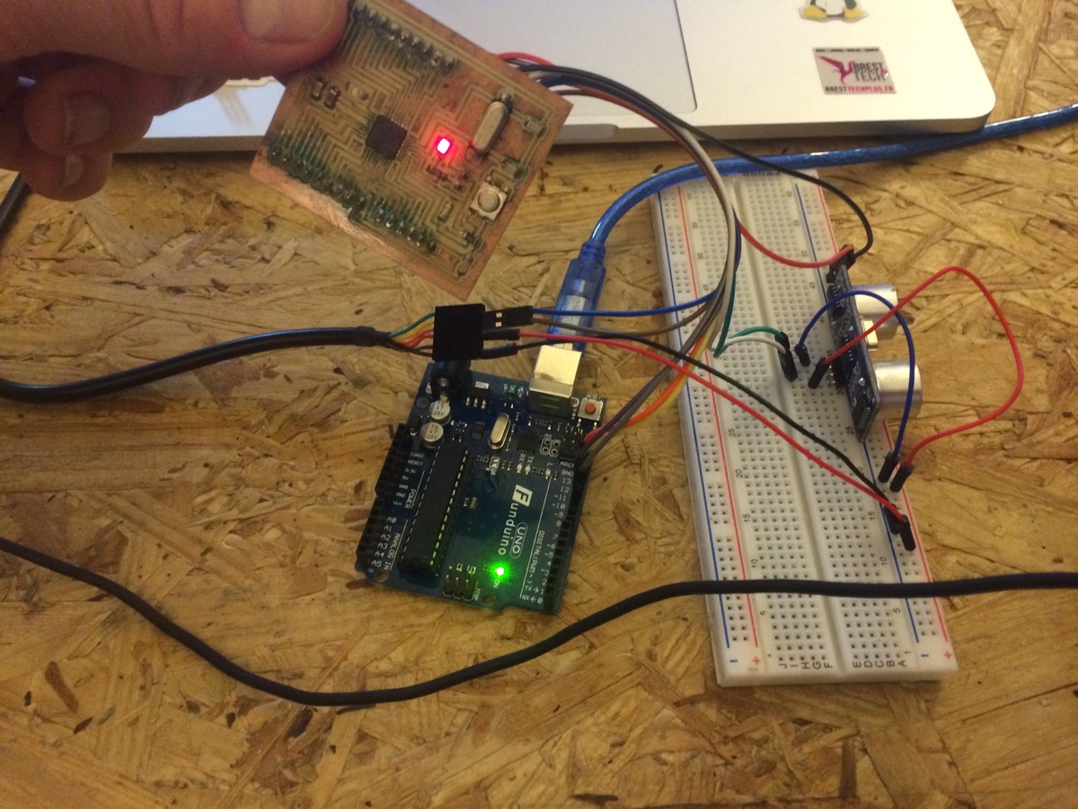
Programming with an Input Device: SR04 Ultrasonic Sensor
I use a ultra sound sensor as Input Device, the aim is to be able to define a distance in a box, as I could do in my new final project (to check if there is some seeds in the tank of my birdhouse)
|
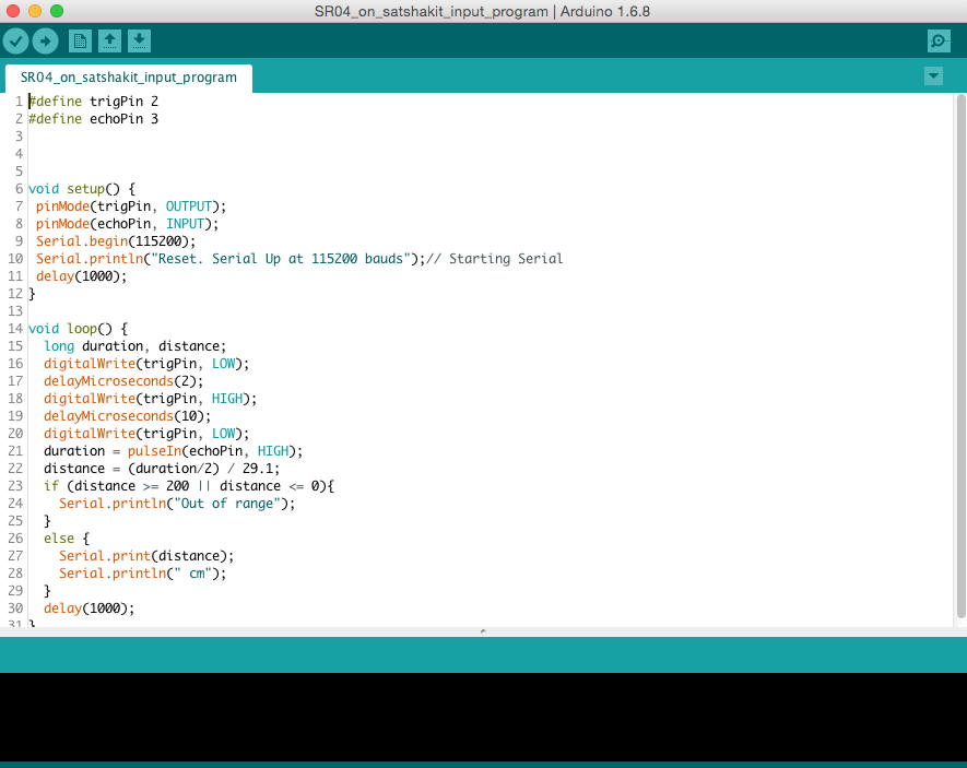
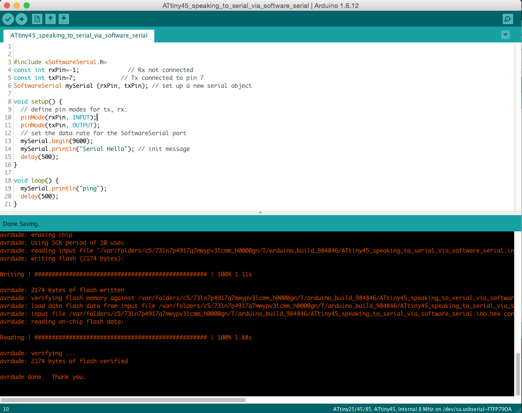
Here is my program
The aim is to get as an output the distance mesured by the sensor
|
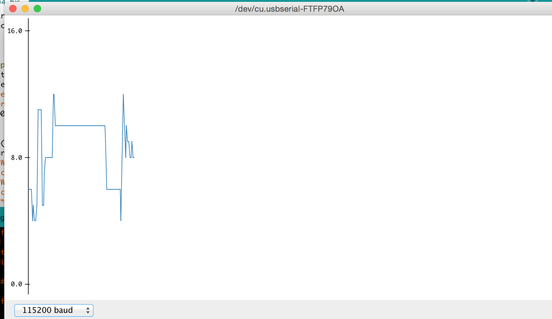
Serial Plotter view
|
|
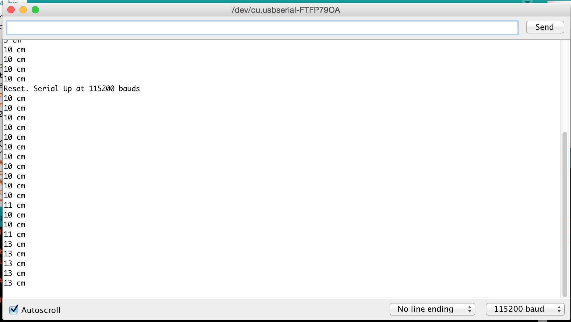
Serial Monitor view
|
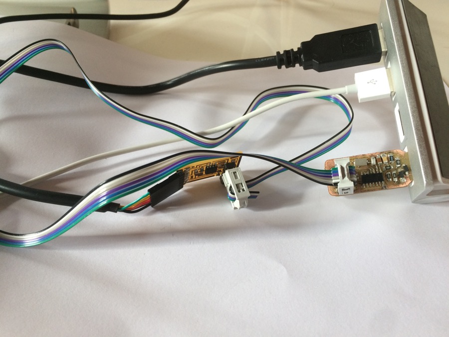
Wire connections
Arduino Uno is only use as a Programmer
|
Video
2ND ROUND
Doing more Input Devices
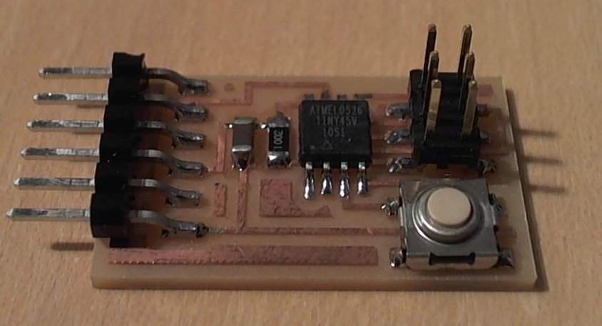
Niel's switch board
In order to improve my knowledge in input devices, I decided to redo the Niel's switch board. All outputs files and programs are above in the summary table at the top of the page.
|
Here is the Neil's original board
|
Using the FabModule to generate the Gcode.See the related .png and .rml files in the ouputs at the top of the page.
|
|
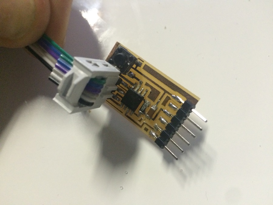
Here is my board
|
Programming the board with my FabISP
|
|
Learning how to use Software Serial, in order to get an output in the Arduino IDE Serial Monitor via the FTDI cableSee the program ATtiny45_speaking_to_serial_via_software_Serial in the ouputs at the top of the page
|
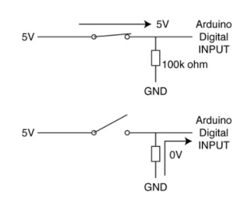
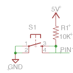
Learning about pull-down resistor ... (resistor external to the microcontroler, to be put on PCB)
|
|
... and about pull-up resistors (resistor internal to the microcontroler, that we can enable on the button Input PIN by programming)
|
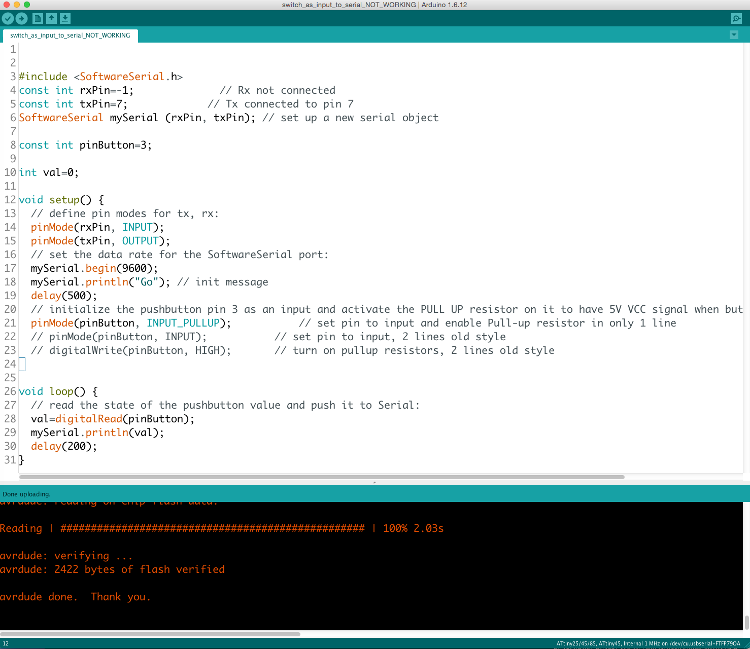
Trying to push state of the button pin to Serial, using pull-up resistorUsing commands "pinMode(pinButton, INPUT_PULLUP);"and command "val=digitalRead(pinButton);"But it is not working, even using old style (2 lines style) for pinMode or using analogRead or disabling pull_up resistorOutput is not relevant, I got it changing, but not going to 0 when pressing the button, looks like I'm not reading the good info from attiny, and I'm not sure pull-up is correctly enabled.See the program Switch_as_input_to_serial_NOT_WORKING in the ouputs at the top of the page.
|
|
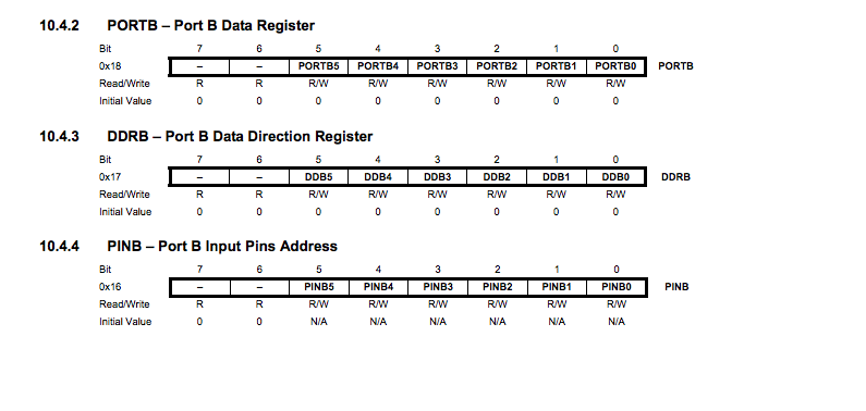
Push state of the button pin to Serial with successNow using the "avr/io.h" library, cbi and sbi definitions,using cbi and sbi to configure input pin with pull-up resistor (DDRB and PORTB register bits of PB4),and reading the PINB register bit of PB4 to get the relevant info.See the program Switch_as_input_to_serial_WORKING in the ouputs at the top of the page.
|
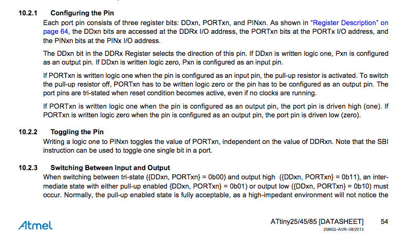
Learning how to configure Pin in the Attiny datasheet page 54,this page explains that each port pin consists of three register bits: DDxn, PORTxn, and PINxn
|
|
And in the Attiny datasheet page 64,is described the register bits PORTB, DDRB (that I used in my program to configure pin) and PINB (that I used in my program to read pin)
|

Video
Here is the program working! :-)
Output on Serial Monitor is 1 when button not pushed(because pull_up resistor is enabled), and 0 when button is pushed