INPUT DEVICES
IntroductionBounce and debounce switch
Bouncing is the tendency of any two metal contacts in an electronic device to generate multiple signals as the contacts close or open; debouncing is any kind of hardware device or software that ensures that only a single signal will be acted upon for a single opening or closing of a contact.
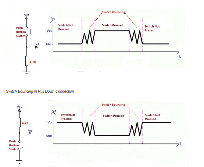
The bouncing of swithes is not big issue but when it comes to the logical circuits its an "ISSUE" for example when we use counter and the the out put value wont be correct due to bouncing effect.Removal of this effect is called debouncing it can be done 4 ways:-
- Hardware Debouncing
- R-C Debouncing
- Software Debouncing
- Debounce IC
Uses two cross coupled NAND gates which form an S-R latch along with a resistor.
Will be using an capacitor to filter quick fluctuations in the switch signal
Sampling of the switch signal either by counter or shift register method
specialized IC's are used,eg:MAX 68(16 or 17 or 18)
What is a sensor?
A device which detects or measures a physical property and records, indicates, or otherwise responds to it.
List of sensors
In which i have gone through some of them :-
- Ultrasonic sensor
- Water level sensor
- Photodiode
- Gyroscope
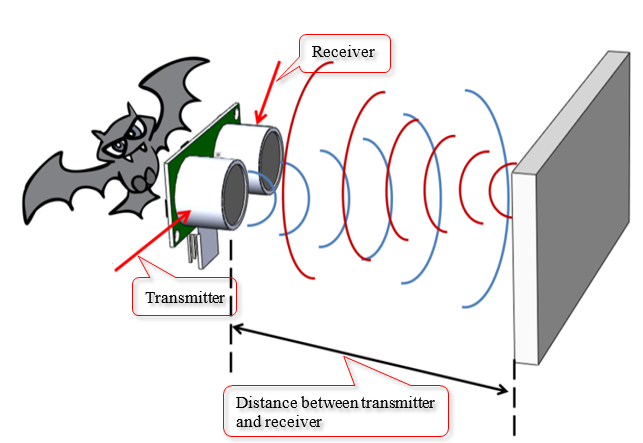
The basic principle of the ultrasomic sensor that it emits the sonic waves by the transducer which is reflected back by an object to the transducer once the waves are emitted the transducer switch to the recieve mode so the distanc eis calculated such way that,it measures the time interval between the emitting and recieving
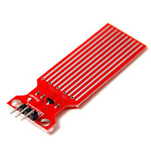
This sensor stick senses the level of water in which its dipped into the tank,where it needs VCC,GND and the datapin which is connected to the microcontroller and which retieves information about the water level,there are also water level indicator with ultrasonic transducres which use same methodolgy in a normal ultrasonic sensor
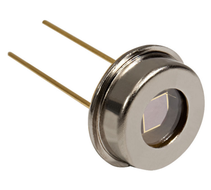
A photodiode is a semiconductor device that converts light into current,The photocurrent thus generated is proportional to the absorbed light intensity.The photocurrent is due to the formation of electron-hole pairs because of the absorption of light in the intrinsic or depletion region
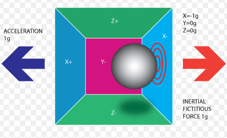
It is calibrated to give a reading of zero when the device is kept on a plane horizontal surface. Any change in orientation of the device is measured by the gyro sensor
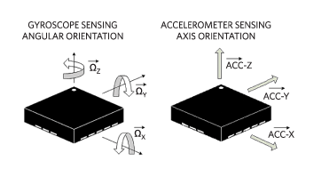
what is the difference between accelerometer and gyroscope?
An accelerometer measures force in each of its axis, if it is a 3 axis accelerometer, then on all the three axis. A gyro measures the angular velocity with respect to the body axis.
Mositure sensor
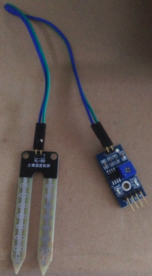
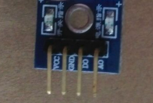
The Soil Moisture Sensor uses capacitance to measure dielectric permittivity of the surrounding medium. In soil dielectric permittivity is a function of the water content. The sensor creates a voltage proportional to the dielectric permittivity, and therefore the water content of the soil.
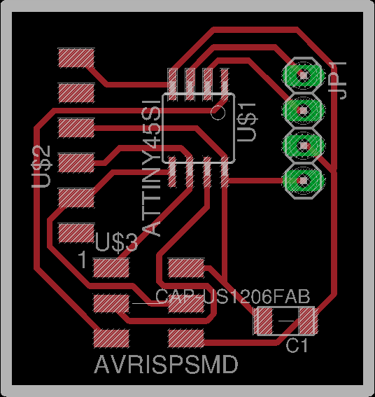
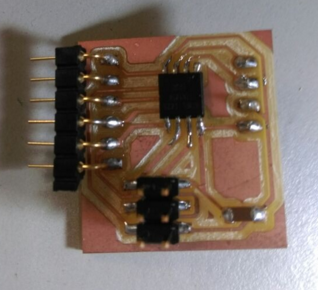
Board
This is my design of the board i used Attiny 45 and i only need one pin to sense the value and a ground and VCC also need FTDI slot since i am retrieving serial data
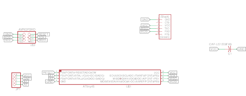
Here goes the schematic
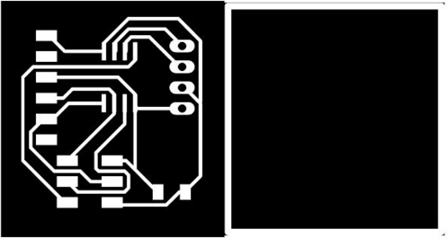
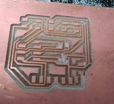
This is the trace and cutpart of the board
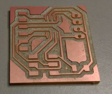
I have milled the board, all good till now.
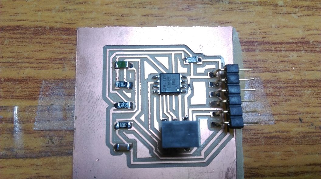
stuffed the same
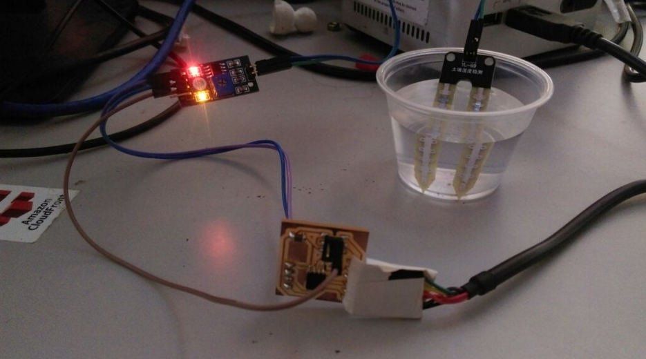
Here goes the setup,sensor is connected to my microcontroller board and the measure stivk is placed in a glass of water i can obtain digital or analog data based on the code and pin connected to the sensor(A0 or D0)
Code
i used the following code :-
              #include <SoftwareSerial.h>

   #define RxD 1

   #define TxD 0


   SoftwareSerial moistureSerial(RxD,TxD);


 int sensor =0;

   void setup() {


     moistureSerial.begin(9600);

   }

   void loop()


   {


   if(moistureSerial.available() ){


    moistureSerial.println("Moisture Level");


       sensor = analogRead(A2);

    moistureSerial.println(sensor);

  delay(1000);

   }

   }
this snapshot displays the variation caused when the moisture sensor is dipped into water bowl and took off
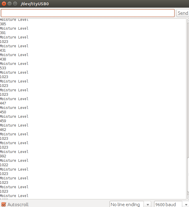
This is the video explaining the variation in the serial monitor
You can download Files here.
TRY 2
I made a try with thermistor too when i got time i modified the neil's design
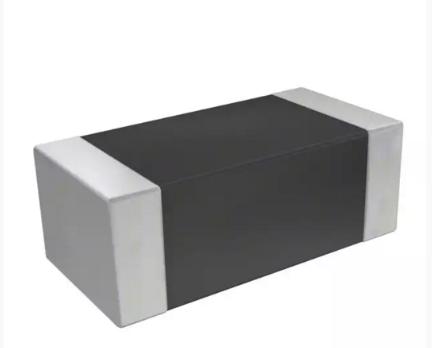
Thermistor
learning what is differance between thermistor and temperature sensor? with this question i have reached to NTC and RTD concepts and understood following things,This Document also helped to get a over all glimpse.
- With NTC, resistance Decreases with temperature to protect against inrush overcurrent conditions. Installed series in a circuit.
- With PTC, resistance Increases with temperature to protect against overvoltage conditions. Installed parallel in a circuit.
- With RTD are useful over larger temperature ranges, while thermistors typically achieve a greater precision within a limited temperature range, typically −90°C to 130°C
Here i am using Thermistor NTC 10k OHM 10%
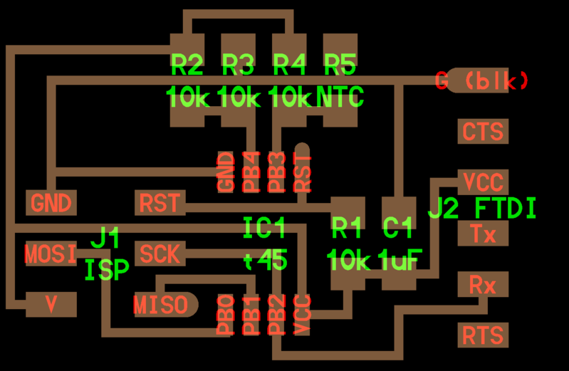
Making of board
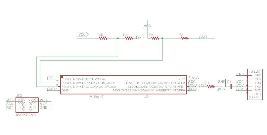
Schematic
Here goes the schematic design of my baord
Design
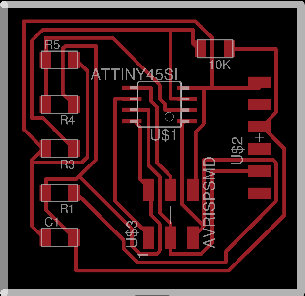
Trace and cutpart
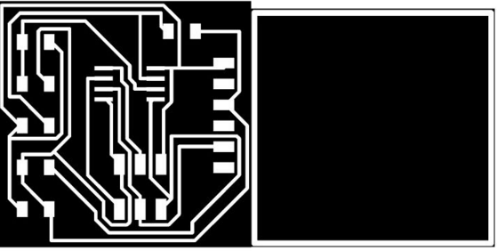
Milled
Stuffed
I used the following niel'scode.
You can download Files here.