
Input Devices
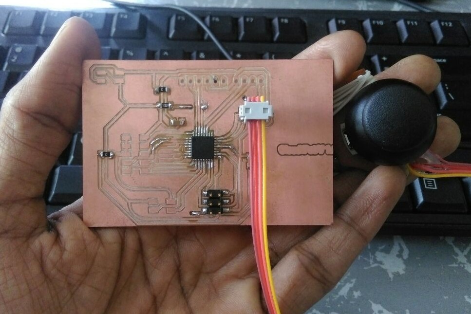
The assignment for this week is to "measure something: add a sensor to a microcontroller board that you have designed and read it". My plan is to make something which will be also useful for my final project. So I decided to interface a dual axis joystick using the ADC interface of micro controller. Simply a joystick consists of two potentio meters. When we move the knob of joystick the potentio meter gives different analog voltage according to the position of the knob. So measuring the analog voltage from the two pots we can determine four (or more) conditions from the joystick.
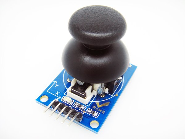
When we move the knob in X and Y axes the analog value in A1 and A2 varies. Measuring this value we can determine the position of the joystick knob.
Design
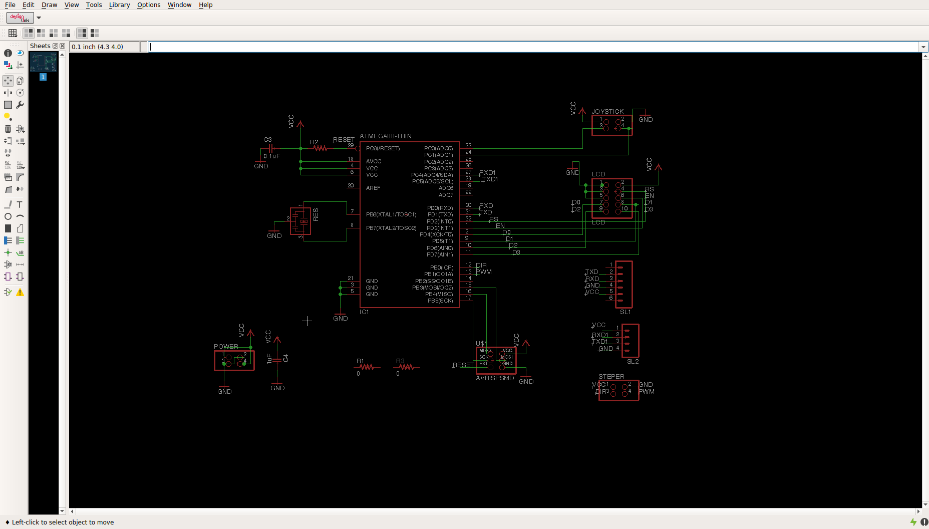
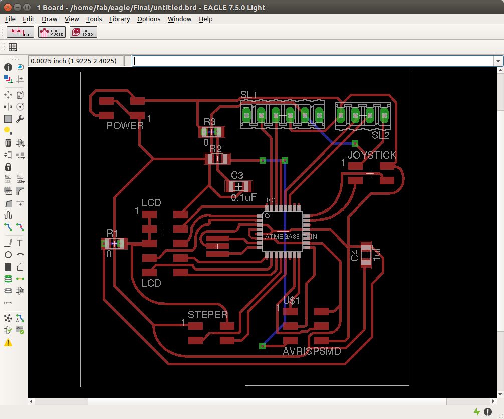
I am planning to design a board which can be used for my project also. SO it hase some pins for joystick and someher pins also for serial communication , stepper motor controlling etc. Anyway the chip i am going to use is atmega 328p.
The registers related to ADC are
Lets go deeper. The first step is to initialize the ADC. So for that we have to decide which is our reference voltage. If we have an external voltage as reference we can choose that, or we can connect the Vref to internal reference voltage. REFS1 and REFS0 in ADMUX is used to select that.
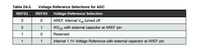
ADMUX |= (1<< REFS0);
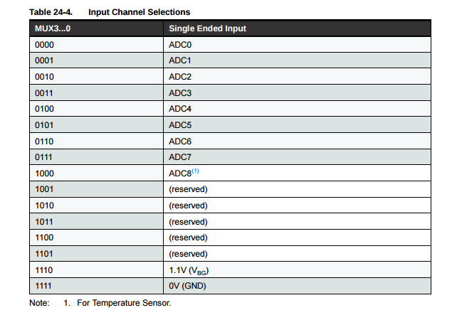
To set which channel is using for ADC, we have four bits in the ADMUX register which are MUX3-0.
Next we go to the ADCSRA register. Here we have the ADEN pin which enables the ADC. If we write 1 to ADEN then ADC is turned on. If we write 0, the ADC is turned off.
Next thing is to select the clock prescaler. The prescaler divide the clock by a factor for the ADC. We have 7 different prescale factors which can be selected by ADPS2-0 bits in ADCSRA register.
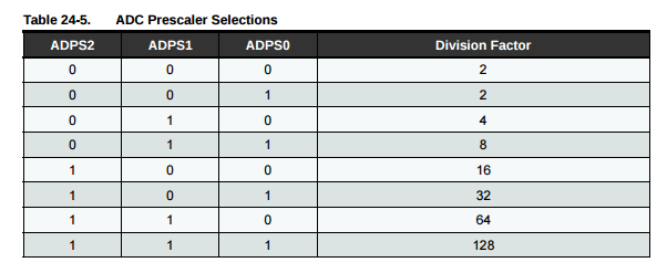
So for this register the total change we need to make is :
ADCSRA |= (1<< ADPS2)|(1<< ADPS1)|(1<< ADPS0)|(1<< ADEN);
    #include <avr/io.h>
    #define F_CPU 8000000
    #include <util/delay.h>

    void InitADC(){

        ADMUX |= (1<< REFS0);

        ADCSRA |= (1<< ADPS2)|(1<< ADPS1)|(1<< ADPS0)|(1<< ADEN);
    }

    uint16_t ReadADC(uint8_t ADCchannel){           // in order to use any channel

        ADMUX = (ADMUX & 0xF0) | (ADCchannel & 0x0F);

        ADCSRA |= (1<< ADSC);

        while( ADCSRA & (1<< ADSC) );
        return ADC;
    }

    int main(){

    int adc0, adc1;
    InitADC();


        while(1){


            adc0 = ReadADC(0);      // read the adc valuein channel 0
            adc1 =  ReadADC(1);     // Read the adc value in channel 1


        }


    }
The connections are made like:
I have written the code in C which will read the ADC value and send some values via UART. The chip is connected to PC via FTDI connector. I have written a simple python program for animating a circle using the joystick. The circle will move left and right when we move the joystick.
Here is the C Code for the Atmega328p. Here is the Python code which run in the PC