Week 8: Embedded Programming
This week finishing off the assignments is a marathon race for me. Well, still
this run is quite worthwhile since I finally got to meet Prof. Neil. :) I'm also, so
happy to visit Vigyan Ashram, Pune (FabLab - 0), where the whole fab lab concept initially began.
It was such a great experience to visit this place where there is grass root level innovation
done by people for the problems they encounter in their day to day life.
But all these travellings should not interrupt you from finishing off the fab assignments!!!
Afterall Neil did ask at Vigyan Ashram, "Did you all complete your Assignments???" :D
 Happy moment clicking a picture together
Assignment:
- Read the data sheet of AVR.
- Program your Hello World Board
- Have a taste of different programming languages - C, Assembly Language, etc.
"Reading the Data Sheet is the Old School method to get to know deeper!"
I'm remembering my mentor in electronics, Prasanth Sir, telling me the above dialogue.
Nisha, to understand things better, read the data sheet and grab points from there.
It's better being old school. He made it a point, that you go through the
data sheet of each components used in the project. Initially, It was ridiculous.
But then later on, I started understanding the benefits. If you need to design something your own
from scratch, it's better to get deeper insights. Debugging too would be easier.
Insights about AVR from the datasheet...
The Data Sheet given was of ATtiny 24A/44A/84A. These are 8 bit Microcontroller
with 2K/4K/8K bytes In-System Programmable Flash. Memories in a microcontroller
are categorised into 5 of them, mainly - Registers, SRAM, DRAM, EEPROM and Flash.
These also have 128/256/512 Bytes of In-System Programmable EEPROM and Internal SRAM.
These follow advanced RISC (Reduced Instruction Set) Architecture.
Peripherals includes a 10 bit Analog to digital Converter, On Chip Analog Comparator,
Timer, Counter, On -chip Oscillator, Universal serial Interface (USB, USART).
ATtiny 44A which is the MCU used for my hello world board is 14 pin SMD.
The first leg/pin is Vcc where the input voltage is supplied to power up
the MCU and leg number 14 is the ground. To understand the pins, usually
there is a notch near the pin 1 of the MCU. Also, leg 4 can act
as RESET pin. This leg can also be used as I/O pin.
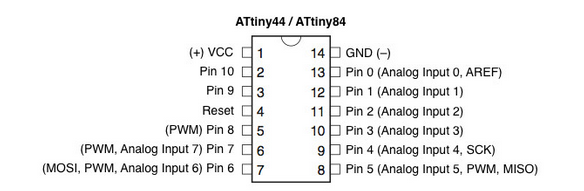
So, looking into the pin out diagram, and with the knowledge in electronic
components and data sheets i've browsed before. It is clear that leg 2 and 3
are in between where we connect the external oscillator, to give external
clock inputs. Giving external oscillator is not necessary as there are inbuild oscillators too.
You can use legs 2,3,4,5,6,7,8,9,10,11,12,13 for connecting I/O devices.
But then we need to keep aside a few legs of these for providing the external
crystal oscillator, RESET and serial communication. ADC pins are 6,7,8,9,10,11,12,13.
Special Pins like ADC and PWM
Microcontrollers are capable of detecting binary signals: is the button pressed or not?
These are digital signals. When a microcontroller is powered from five volts, it
understands zero volts (0V) as a binary 0 and a five volts (5V) as a binary 1.
The world however is not so simple and likes to use shades of gray.
What if the signal is 2.72V? Is that a zero or a one? We often need to
measure signals that vary; these are called analog signals. A 5V analog
sensor may output 0.01V or 4.99V or anything in between. Analog to Digital Converters (ADC's) are
the devices that allow to convert these values of voltage in such a manner that we
can use them to program and make decisions. These ADC pins serves the purpose.
So, connecting of input devices such as accelerometers and gyrometers must be done along these
pins.
You can describe Pulse width modulation (PWM) as a fancy term for a
type of digital signal. Pulse width modulation is used in a variety of
applications including to control dimming of RGB LEDs or to control the direction of a servo motor.
Pulse width modulation allows us to vary how much time the signal is high
in an analog fashion. While the signal can only be high (usually 5V) or low (ground) at any time,
we can change the proportion of time the signal is high compared to when it is low over a
consistent time interval. So, PWM pins can be used with particular applications
needing control
The next section of data sheet covers block diagrams and explaining about functions
and specs of each components in the block diagram. It might take me atleast 2 whole
week to read entire sheet, what's better is to take what you need while designing
the circuit and leave the rest. When you have time to gain more knowledge,
you could always come back and read the working and what each bits in each
register accomodates and all. Data sheet is taken into consideration while
designing the circuit and while programming the board. Data Sheet is Reality, in short
what a processor can do.
Programming my Hello World Board
I need to try programming hello world board with Arduino IDE and using
C programming with avrdude. I wonder how much I could finish off learning assembly
language. And thought to gain extra credit needs to be put off. Let's complete
programming the board in various languages a first.
My flexible hello world board has a trace brocken, well flexible circuits
when not taken proper care can just have their trace snipped off easily. So,
I also needs to solder and join the trace. let's see what needs to be done.
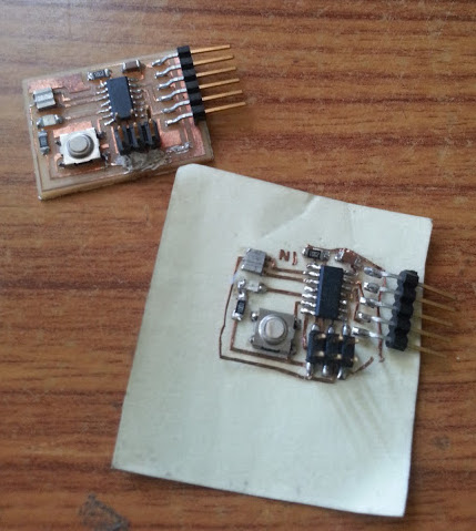
Seeing to the state of the flexible hello world board, I've come to a conclusion that:
- There is no point in trying to fix it. I've learnt a very important lesson, don't just let you circuit lie here
and there. Some one might by mistake tamper it and the traces would get broken.
- There is no point in milling another hello world board. Well, you have done that
part, let's move on to higher circuits
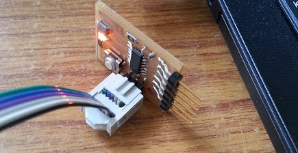
So, I decided to debugg my hello world board I've milled for pre fab and use it to learn
embedded programming. The previous hello world board got damaged while I dropped
it. The ISP header just came off, taking the traces along with it. You can't resolder it,
since the traces too came off. Later, I stuck it in place and tried to program the board.
The board wasn't getting programmed. So, I realised that there is some issue with the
board and need to debugg. Using multimeter I checked for connectivity between each traces and components.
There was a connectivity issue found at the 4th pin (MOSI pin). Just to hack it, I joined the
missing trace using a wire.
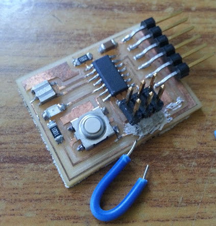
 connecting the missing trace...
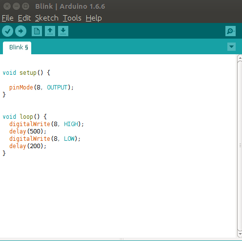
To begin off with I used, arduino IDE for programming. Initially,I used my old fabisp to program the board.
My fab isp had some issues that it was not being detected by computer. So, just to check up that the hello world
board is working fine, I just loaded the blink program in the arduino examples after changing the pin number to 8 (which
is the pin to which the LED is connected). It was good to see it working perfectly fine while programmed.
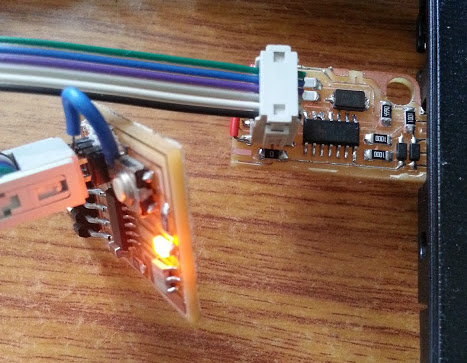
 Yes, the board blinks. It's a working board!
Seeing to the hello world board working fine, my next goal was to debug and solve the issue with
my valencin fabisp board. As usual routine, I begin off with checking for any connectivity
issues in my board. After a lot of tries, I still couldn't find the issue. Later on, I discussed
the issue with Nadeem,
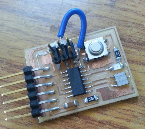
who also milled out the same board. He explained that it seems that when the
fuse was stripped off by breaking the board, during when the trace going to supply voltage is also snipped out. So,
externally you need to give a connection to power up the board. As, he suggested I gave an external
wired connection also to the FabISP board.
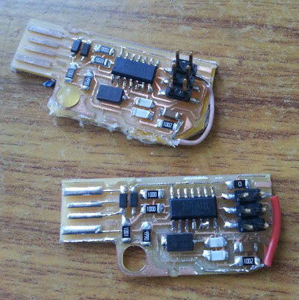 On connecting external wired connection to FabISP board
Inspite of this, the board was not up. I then took the circuit diagram and started checking whether,
any traces where missing as such. That's when I found out that there was a trace that looked joined
when milled which resulted in a short. Thank's to the magnifying loop.
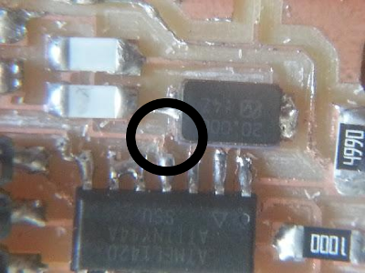 The joint trace!
After resolving this, by removing that part of overlap, the FabISP was finally recognised and been able
to program the board.
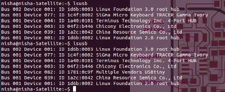 lsusb showing the fabisp
The Blink Program...
Now, I could finally move on to starting using C and assembly language to program my board.
I know Arduino IDE, and programming using it, so may be after writing a program to try out to use button to
control the LED, I will be moving on to other languages. Thou' I didn't learn a new programming language,
I'm pretty happy that I could debugg both my board.
Also, planning to seal the board as Sibu
have done, so that next time I drop the Components won't come off.
After this I just programmed the board to turn on and off the led when the button is pressed.
Then I programmed to do SOS blinking ( . . . - - - . . .) that is blinking led in the dot and dash fashion
of morse code.
C Programming...
I started off learning C using the tutorial book provided
by Learn C Code the hard way. Learning C makes you a better programmer and ya it's
harder compared to IDE's, but that's just because C is not hiding things from you...Your
job is to know what's going on, and so C would be a good option to start with!
I learnt C programming and recreated all the above arduino programs in C. You can find the codes
below.
Download Files:
Arduino Files n zip
C code and Make files (of SOS program) in zip
What I learnt from this week's schedule...
How to program in C.
C comparitatively might be harder to the IDE's like arduino IDE's but way more functional